-
Cisco IOS Voice Command Reference
-
About Cisco IOS Software Documentation
-
Using Cisco IOS Software
-
Commands: A
-
Commands: B
-
Commands:cac master through call application stats
-
Commands: call application voice through call-denial
-
Commands: call fallback through called-number (dial-peer)
-
Commands: caller-id (dial peer) through ccm-manager switchover-to-backup
-
Commands: ccs connect (controller) through clear vsp statistics
-
Commands: clid through cptone
-
Commands: default (MGCP profile) through direct-inward-dial
-
Commands: disable-early-media 180 through dualtone
-
Commands: E
-
Commands: F
-
Commands: G
-
Commands: H
-
Commands: icpif through irq global-request
-
Commands: isdn bind-l3 through ixi transport http
-
Commands: K
-
Commands: L
-
Commands: map q850-cause through mgcp package-capability
-
Commands: mgcp persistent through mmoip aaa send-id secondary
-
Commands: mode (ATM/T1/E1 controller) through mwi-server
-
Commands: N
-
Commands: O
-
Commands: package through pattern
-
Commands: permit hostname through proxy h323
-
Commands: Q
-
Commands: R
-
Commands: sccp through service-type call-check
-
Commands: session through sgcp tse payload
-
Commands: show aal2 profile through show call filter match-list
-
Commands: show call history fax through show debug condition
-
Commands: show dial-peer video through show gatekeeper zone status
-
Commands: show gateway through show modem relay statistics
-
Commands: show mrcp client session active through show sgcp statistics
-
Commands: show sip service through show trunk hdlc
-
Commands: show vdev through show voice statistics memory-usage
-
Commands: show voice translation-profile through shutdown (voice-port)
-
Commands: signal through srv version
-
Commands: ss7 mtp2-variant through switchover method
-
Commands: target carrier-id through threshold noise
-
Commands: timeout (auto-config application) through timing clear-wait
-
Commands:timing delay-duration through type (voice)
-
Commands: U
-
Commands: vad (dial peer) through voice class dualtone-detect-params
-
Commands: voice class h323 through vxml tree memory
-
Commands: W
-
Commands: Z
-
 Feedback
Table Of Contents
conference-leave custom-cptone
clid
To preauthenticate calls on the basis of the Calling Line Identification (CLID) number, use the clid command in AAA preauthentication configuration mode. To remove the clid command from your configuration, use the no form of this command.
clid [if-avail | required] [accept-stop] [password password]
no clid [if-avail | required] [accept-stop] [password password]
Syntax Description
Command Default
The if-avail and required keywords are mutually exclusive. If the if-avail keyword is not configured, the preauthentication setting defaults to required.
The default password string is cisco.
Command Modes
AAA preauthentication configuration
Command History
Usage Guidelines
You may configure more than one of the authentication, authorization and accounting (AAA) preauthentication commands (clid, ctype, dnis) to set conditions for preauthentication. The sequence of the command configuration decides the sequence of the preauthentication conditions. For example, if you configure dnis, then clid, then ctype, in this order, then this is the order of the conditions considered in the preauthentication process.
In addition to using the preauthentication commands to configure preauthentication on the Cisco router, you must set up the preauthentication profiles on the RADIUS server.
Examples
The following example specifies that incoming calls be preauthenticated on the basis of the CLID number:
aaa preauthgroup radiusclid requiredRelated Commands
clid (dial peer)
To control the presentation and use of calling-line ID (CLID) information, use the clid command in dial peer configuration mode. To remove CLID controls, use the no form of this command.
clid {network-number number [second-number strip] | network-provided | overrider dnis | restrict | strip [name | pi-restrict [all]] | substitute name}
no clid {network-number number [second-number strip] | network-provided | overrider dnis | restrict | strip [name | pi-restrict [all]] | substitute name}
Syntax Description
Command Default
No default behavior or values
Command Modes
Dial peer configuration
Command History
Usage Guidelines
The override rdnis keywords are supported only for POTS dial peers.
CLID is the collection of information about the billing telephone number from which a call originated. The CLID value might be the entire phone number, the area code, or the area code plus the local exchange. It is also known as caller ID. The various keywords to this command manage the presentation, restriction, or stripping of the various CLID elements.
The clid network-number command sets the presentation indicator to "y" and the screening indicator to "network-provided." The second-number strip keyword strips from the H.225 source-address field the original calling-party number, and is valid only if a network number was previously configured.
The clid override rdnis command overrides the CLID with the RDNIS if it is available.
The clid restrict command causes the calling-party number to be present in the information element, but the presentation indicator is set to "n" to prevent its presentation to the called party.
The clid strip command causes the calling-party number to be null in the information element, and the presentation indicator is set to "n" to prevent its presentation to the called party.
Examples
The following example sets the calling-party network number to 98765 for POTS dial peer 4321:
Router(config)# dial-peer voice 4321 potsRouter(config-dial-peer)# clid network-number 98765An alternative method of accomplishing this result is to enter the second-number strip keywords as part of the clid network-number command. The following example sets the calling-party network number to 56789 for VoIP dial peer 1234 and also prevents the second network number from being sent:
Router(config)# dial-peer voice 1234 voipRouter(config-dial-peer)# clid network-number 56789 second-number stripThe following example overrides the calling-party number with RDNIS if available:
Router(config-dial-peer)# clid override rdnisThe following example prevents the calling-party number from being presented:
Router(config-dial-peer)# clid restrictThe following example removes the calling-party number from the CLID information and prevents the calling-party number from being presented:
Router(config-dial-peer)# clid stripThe following example strips the name from the CLID information and prevents the name from being presented:
Router(config-dial-peer)# clid strip nameThe following example strips the calling party number when PI is set to restrict clid strip from the CLID information and prevents the calling party number from being presented:
Router(config-dial-peer)# clid strip pi-restrictThe following example strips calling party name and number when the PI is set to the restrict all clid strip from the CLID information and prevents the calling party name and number from being presented:
Router(config-dial-peer)# clid strip pi-restrict allThe following example substitutes the calling party number into the display name:
Router(config-dial-peer)# clid substitute nameThe following example allows you to set the screening indicator to reflect that the number was provided by the network:
Router(config-dial-peer)# clid network-providedRelated Commands
clid (voice-service-voip)
Passes the network-provided ISDN numbers in an ISDN calling party information element screening indicator field, removes the calling party name and number from the calling-line identifier in voice service voip configuration mode, or allows a presentation of the calling number by substituting for the missing Display Name field in the Remote-Party-ID and From headers.
clid {network-provided | strip pi-restrict all | substitute name}
no clid {network-provided | strip pi-restrict all | substitute name}
Syntax Description
Command Default
The clid (voice-service-voip) command passes along user-provided ISDN numbers in an ISDN calling party information element screening indicator field.
Command Modes
Voice-service-VoIP configuration
Command History
Usage Guidelines
Use the clid network-provided keyword to pass along network-provided ISDN numbers in an ISDN calling party information element screening indicator field.
Use the clid strip pi-restrict all keyword to remove the Calling Party Name and Calling Party Number from the CLID.
Use the clid substitute name keyword to allow a presentation of the Display Name field in the Remote-Party-ID and From headers. The Calling Number is substituted for the Display Name field.
Examples
The following passes along network-provided ISDN numbers in an ISDN calling party information element screening indicator field:
Router(conf-voi-serv)# clid network-providedThe following passes along user-provided ISDN numbers in an ISDN calling party information element screening indicator field:
Router(conf-voi-serv)# no clid network-providedThe following removes the calling party name and number from the calling-line identifier (CLID):
Router(conf-voi-serv)# clid strip pi-restrict allThe following does not remove the calling party name and number from the CLID:
Router(conf-voi-serv)# no clid strip pi-restrict allThe following allows the presentation of the calling number to be substituted for the missing Display Name field in the Remote-Party-ID and From headers:
Router(conf-voi-serv)# clid substitute nameThe following disallows the presentation of the calling number to be substituted for the missing Display Name field in the Remote-Party-ID and From headers:
Router(conf-voi-serv)# no clid substitute nameRelated Commands
clid (dial peer)
Controls the presentation and use of CLID information in dial peer configuration mode.
clid strip
To remove the calling-party number from calling-line-ID (CLID) information and to prevent the calling-party number from being presented to the called party, use the clid strip command in dial peer configuration mode. To remove the restriction, use the no form of this command.
clid strip [name]
no clid strip [name]
Syntax Description
Command Default
Calling-party number and name are included in the CLID information.
Command Modes
Dial peer configuration
Command History
Usage Guidelines
If the clid strip command is issued, the calling-party number is null in the information element, and the presentation indicator is set to "n" to prevent the presentation of the number to the called party.
If you want to remove both the number and the name, you must issue the command twice, once with the name keyword.
Examples
The following example removes the calling-party number from the CLID information and prevents the calling-party number from being presented:
Router(config-dial-peer)# clid stripThe following example removes both the calling-party number and the calling-party name from the caller-ID display:
Router(config-dial-peer)# clid stripRouter(config-dial-peer)# clid strip nameRelated Commands
clock-select
To establish the sources and priorities of the requisite clocking signals for the OC-3/STM-1 ATM Circuit Emulation Service network module, use the clock-select command in CES configuration mode.
clock-select priority-number interface slot/port
Syntax Description
Command Default
No default behavior or values
Command Modes
CES configuration
Command History
Usage Guidelines
This command is used on Cisco 3600 series routers that have OC-3/STM-1 ATM CES network modules.
To support synchronous or synchronous residual time stamp (SRTS) clocking modes, you must specify a primary reference source to synchronize the flow of constant bit rate (CBR) data from its source to its destination.
You can specify up to four clock priorities. The highest priority active interface in the router supplies primary reference source to all other interfaces that require network clock synchronization services. The fifth priority is the local oscillator on the network module.
Use the show ces clock-select command to display the currently configured clock priorities on the router.
Examples
The following example defines two clock priorities on the router:
clock-select 1 cbr 2/0clock-select 2 atm 2/0Related Commands
codec (dial peer)
To specify the voice coder rate of speech for a dial peer, use the codec command in dial peer configuration mode. To reset the default value, use the no form of this command.
Cisco 1750 and Cisco 1751 Modular Access Routers, Cisco AS5300 and AS5800 Universal Access Servers, and Cisco MC3810 Multiservice Concentrators
codec codec [bytes payload-size]
no codec codec [bytes payload-size]
Cisco 2600 and 3600 Series Routers and Cisco 7200 and 7500 Series Routers
codec {codec [bytes payload-size] | transparent}
no codec {codec [bytes payload-size] | transparent}
Syntax Description
codec
codec options available for various platforms are described in Table 11.
bytes
(Optional) Specifies the number of bytes in the voice payload of each frame.
payload-size
(Optional) Number of bytes in the voice payload of each frame. See Table 12 for valid entries and default values.
transparent
Enables codec capabilities to be passed transparently between endpoints in a Cisco Multiservice IP-to-IP Gateway.
Note
The transparent keyword is only available on the Cisco 2600 and 3600 Series Router and Cisco 7200 and 7500 Series Router platforms.
Command Default
g729r8, 30-byte payload for VoFR and VoATM.
g729r8, 20-byte payload for VoIP.
See Table 12 for valid entries and default values.Command Modes
dial peer configuration
Command History
Usage Guidelines
Use this command to define a specific voice coder rate of speech and payload size for a VoIP or VoFR dial peer. This command is also used for VoATM.
A specific codec type can be configured on the dial peer as long as the codec is supported by the setting used with the codec complexity voice-card configuration command. The codec complexity command is voice-card specific and platform specific. The codec complexity voice-card configuration command is set to either high or medium.
If the codec complexity command is set to high, the following keywords are available: g711alaw, g711ulaw, g723ar53, g723ar63, g723r53, g723r63, g726r16, g726r24, g726r32, g728, g729r8, and g729br8.
If the codec complexity command is set to medium, the following keywords are available: g711alaw, g711ulaw, g726r16, g726r24, g726r32, g729r8, and g729br8.
The codec dial peer configuration command is particularly useful when you must change to a small-bandwidth codec. Large-bandwidth codecs, such as G.711, do not fit in a small-bandwidth link. However, the g711alaw and g711ulaw codecs provide higher quality voice transmission than other codecs. The g729r8 codec provides near-toll quality with considerable bandwidth savings.
The transparent keyword is available with H.323 to H.323 call connections beginning in Cisco IOS Release 12.2(13)T3. Support for the keyword in H.32 to SIP call connections begins
in Cisco IOS Release 12.4(11)XJ2.If codec values for the dial peers of a connection do not match, the call fails.
You can change the payload of each VoIP frame by using the bytes keyword; you can change the payload of each VoFR frame by using the bytes keyword with the payload-size argument. However, increasing the payload size can add processing delay for each voice packet.
Table 12 describes the voice payload options and default values for the codecs and packet voice protocols.
Note
For toll quality, use the g711alaw or g711ulaw keyword. These values provide high-quality voice transmission but use a significant amount of bandwidth. For nearly toll quality (and a significant savings in bandwidth), use the g729r8 keyword.
Note
Examples
The following example shows how to configure a voice coder rate that provides toll quality voice with a payload of 120 bytes per voice frame on a router that acts as a terminating node. The sample configuration begins in global configuration mode and is for VoFR dial peer 200.
dial-peer voice 200 vofrcodec g711ulaw bytes 240The following example shows how to configure a voice coder rate for VoIP dial peer 10 that provides toll quality but uses a relatively high amount of bandwidth:
dial-peer voice 10 voipcodec g711alawThe following example shows how to configure the transparent codec used by the Cisco Multiservice IP-to-IP Gateway:
dial-peer voice 1 voipincoming called-number .Tdestination-pattern .Tsession target rascodec transparentRelated Commands
codec (dsp)
To specify call density and codec complexity based on a particular codec standard, use the codec command in DSP interface DSP farm configuration mode. To reset the card type to the default, use the no form of the command.
codec {high | med}
no codec {high | med}
Syntax Description
high
Specifies high complexity: two channels of any mix of codec.
med
Specifies medium complexity: four channels of g711/g726/g729a/fax.
Command Default
Medium complexity
Command Modes
DSP interface DSP farm
Command History
Usage Guidelines
This command is supported on only the Cisco 7200 series and Cisco 7500 series routers.
Codec complexity refers to the amount of processing required to perform compression. Codec complexity affects the number of calls, referred to as call density, that can take place on the DSPfarm interfaces. The greater the codec complexity, the fewer the calls that are handled. For example, G.711 requires less DSP processing than G.728, so as long as the bandwidth is available, more calls can be handled simultaneously by using the G.711 standard than by using G.728.
The DSPinterface dspfarm codec complexity setting affects the options available for the codec dial peer configuration command.
To change codec complexity, you must first remove any configured channel associated signaling (CAS) or DS0 groups and then reinstate them after the change.
Note
Examples
The following example configures the DSPfarm interface 1/0 on the Cisco 7200 series routers to support high compression:
dspint DSPFarm 1/0
 codec high
Related Commands
codec (dial peer)
Specifies the voice codec rate of speech for a dial peer.
codec complexity
Specifies call density and codec complexity based on the codec standard you are using.
codec (DSP Farm profile)
To specify the codecs that are supported by a digital signal processor (DSP) farm profile, use the codec command in DSP farm profile configuration mode. To remove the codec, use the no form of this command.
codec {codec-type | pass-through}
no codec {codec-type | pass-through}
Syntax Description
Command Default
Transcoding
•
•
•
•
Conferencing
•
•
•
•
•
•
MTP
•
Command Modes
DSP farm profile configuration
Command History
Usage Guidelines
Only one codec is supported for each Media Termination Point (MTP) profile. To support multiple codecs, you must define a separate MTP profile for each codec.
Hardware MTPs support only G.711 a-law and G.711 u-law. If you configure a profile as a hardware MTP and you want to change the codec to other than G.711, you must first remove the hardware MTP by using the no maximum sessions hardware command.
The pass-through keyword is supported for transcoding and MTP profiles only; the keyword is not supported for conferencing profiles. To support the RSVP agent on a SCCP device, you must use the codec pass-through command. In the pass-through mode, the SCCP device processes the media stream by using a pure software MTP, regardless of the nature of the stream. This enables video and data streams to be processed in addition to audio. When the pass-through mode is set in a transcoding profile, no transcoding is done for the session; the transcoding device performs a pure software MTP function. The pass-through mode can be used for Secure RTP sessions.
Examples
The following example shows the call density and codec complexity set to g729abr8:
Router(config)# dspfarm profile 123 transcodeRouter(config-dspfarm-profile)# codec g729abr8Related Commands
codec aal2-profile
To set the codec profile for a digital signal processor (DSP) on a per-call basis, use the codec aal2-profile command in dial peer configuration mode. To restore the default codec profile, use the no form of this command.
codec aal2-profile {itut | custom | atmf} profile-number codec
no codec aal2-profile
Syntax Description
Command Default
ITU-T profile 1 (G.711 u-law)
Command Modes
Dial peer configuration
Command History
Usage Guidelines
Use this command to configure the DSP to operate with a specified profile type and codecs.
You must enter the session protocol aal2-trunk command before configuring the codec ATM adaptation layer 2 (AAL2) profile.
This command is used instead of the codec (dial peer) command for AAL2 trunk applications.
Examples
The following example sets the codec AAL2 profile type to ITU-T and configures a profile number of 7, enabling codec G.729ar8:
dial-peer voice 100 voatmsession protocol aal2-trunkcodec aal2-profile itut 7 g729ar8The following example sets the codec AAL2 profile type to custom and configures a profile number of 100, enabling codec G.726r32:
dial-peer voice 200 voatmsession protocol aal2-trunkcodec aal2-profile custom 100 g726r32Related Commands
session protocol (dial peer)
Establishes a session protocol for calls between the local and remote routers via the packet network.
codec complexity
To specify call density and codec complexity according to the codec standard that is being used, use the codec complexity command in voice-card configuration mode. To reset the flex complexity default, use the no form of this command.
codec complexity {flex [reservation-fixed {high | medium}] | high | medium | secure}
no codec complexity
Syntax Description
Command Default
flex complexity
Command Modes
Voice-card configuration
Command History
Usage Guidelines
Codec complexity refers to the amount of processing required to perform voice compression. Codec complexity affects the call density—the number of calls reconciled on the DSPs. With higher codec complexity, fewer calls can be handled. Select a higher codec complexity if that is required to support a particular codec or combination of codecs. Select a lower codec complexity to support the greatest number of voice channels, provided that the lower complexity is compatible with the particular codecs in use.
For codec complexity to change, all of the DSP voice channels must be in the idle state.
When you have specified the flex keyword, you can connect (or configure in the case of DS0 groups and PRI groups) more voice channels to the module than the DSPs can accommodate. If all voice channels should go active simultaneously, the DSPs become oversubscribed, and calls that are unable to allocate a DSP resource fail to connect. The flex keyword allows the DSP to process up to 16 channels. In addition to continuing support for configuring a fixed number of channels per DSP, the flex keyword enables the DSP to handle a flexible number of channels. The total number of supported channels varies from 6 to 16, depending on which codec is used for a call. Therefore, the channel density varies from 6 per DSP (high-complexity codec) to 16 per DSP (g.711 codec).
The high keyword selects a higher codec complexity if that is required to support a particular codec or combination of codecs. When you use the codec complexity high command to change codec complexity, the system prompts you to remove all existing DS0 or PRI groups using the specified voice card, then all DSPs are reset, loaded with the specified firmware image, and released.
The medium keyword selects a lower codec complexity to support the greatest number of voice channels, provided that the lower complexity is compatible with the particular codecs in use.
The secure keyword restricts the number of TI-549 DSP channels to 2, which is the lower codec complexity required to support Secure Real-Time Transport Protocol (SRTP) package capability on the NM-HDV and enable media authentication and encryption. If the secure command is not configured then the gateway will not advertise secure capability to Cisco CallManager, resulting in nonsecure calls. You do not need to use any command to specify secure codec complexity for TI-5510 DSPs, which support SRTP capability in all modes. Use the mgcp package-capability srtp-package command to enable MGCP gateway capability to process SRTP packages. Use the show voice dsp command to view codec complexity status.
Examples
The following example sets the codec complexity to high on voice card 1 installed on a router, and configures local calls to bypass the DSP:
voice-card 1codec complexity highlocal-bypassThe following example sets the codec complexity to secure on voice card 1 installed on the NM-HDV, and configures it to support SRTP package processing, media authentication and encryption:
voice-card 1codec complexity secureRelated Commands
codec ilbc
To specify the voice coder rate of speech for a dial peer using the internet Low Bandwidth Codec (iLBC), use the codec ilbc command in dial peer configuration mode. To reset the default value, use the no form of this command.
codec ilbc [mode frame_size [bytes payload_size]]
no codec ilbc [mode frame_size [bytes payload_size]]
Syntax Description
Command Default
20ms frames with a 15.2kbps bit rate.
Command Modes
Dial peer configuration
Command History
Usage Guidelines
Use this command to define a specific voice coder rate of speech and payload size for a VoIP dial peer using an iLBC codec.
If codec values for the dial peers of a connection do not match, the call fails.
You can change the payload of each VoIP frame by using the bytes keyword. However, increasing the payload size can add processing delay for each voice packet.
Examples
The following example shows how to configure the iLBC codec on an IP-to-IP Gateway:
dial-peer voice 1 voiprtp payload-type cisco-codec-ilbc 100codec ilbc mode 30 bytes 200Related Commands
codec gsmamr-nb
To specify the Global System for Mobile Adaptive Multi-Rate Narrow Band (GSMAMR-NB) codec for a dial peer, use the codec gsmamr-nb command in dial peer voice configuration mode. To disable the GSMAMR-NB codec, use the no form of this command.
codec gsmamr-nb [packetization-period 20] [encap rfc3267] [frame-format {bandwidth-efficient | octet-aligned [crc | no-crc]}] [modes modes-value]
no codec gsmamr-nb
Syntax Description
Command Default
Packetization period is 20 ms.
Encapsulation is rfc3267.
Frame format is octet-aligned.
CRC is no-crc.
Modes value is 0-7.Command Modes
Dial peer voice configuration
Command History
12.4(4)XC
This command was introduced.
12.4(9)T
This command was integrated into Cisco IOS Release 12.4(9)T.
Usage Guidelines
The codec gsmamr-nb command configures the GSMAMR-NB codec and its parameters on the Cisco AS5350XM and Cisco AS5400XM platforms.
Examples
The following example sets the codec to gsmamr-nb and sets parameters:
Router(config-dial-peer)# codec gsmamr-nb packetization-period 20 encap rfc3267
frame-format octet-aligned crc
Related Commands
codec complexity
Specifies call density and codec complexity based on the codec used.
show dial peer voice
Displays the codec setting for dial peers.
codec preference
To specify a list of preferred codecs to use on a dial peer, use the codec preference command in voice-class configuration mode. To disable this functionality, use the no form of this command.
codec preference value codec-type [mode frame-size][bytes payload-size] [packetization-period 20] [encap rfc3267] [frame-format {bandwidth-efficient | octet-aligned [crc | no-crc]}] [modes modes-value]
no codec preference value codec-type
Syntax Description
Command Default
If you enter the gsmamr-nb keyword, the default values are as follows:
Packetization period is 20 ms.
Encap is rfc3267.
Frame format is octet-aligned.
CRC is no-crc.
Modes value is 0-7.Command Modes
Voice-class configuration
Command History
Usage Guidelines
The routers at opposite ends of the WAN may have to negotiate the codec selection for the network dial peers. The codec preference command specifies the order of preference for selecting a negotiated codec for the connection. Table 13 describes the voice payload options and default values for the codecs and packet voice protocols.
Note
Examples
The following example show how to set the codec preference to the GSMAMR-NB codec and specify parameters:
Router(config-voice-class)# codec preference 1 gsmamr-nb packetization-period 20 encap
rfc3267 frame-format octet-aligned crc
The following example shows how to create codec preference list 99 and applies it to dial peer 1919:
voice class codec 99codec preference 1 g711alawcodec preference 2 g711ulaw bytes 80codec preference 3 g723ar53codec preference 4 g723ar63 bytes 144codec preference 5 g723r53codec preference 6 g723r63 bytes 120codec preference 7 g726r16codec preference 8 g726r24codec preference 9 g726r32 bytes 80codec preference 10 g729br8codec preference 11 g729r8 bytes 50enddial-peer voice 1919 voipvoice-class codec 99The following example shows how to configure the transparent codec used by the Cisco Multiservice IP-to-IP gateway:
voice class codec 99codec preference 1 transparent
Note
The following example shows how to configure the iLBC codec used by the Cisco Multiservice IP-to-IP Gateway:
voice class codec 99codec preference 1 ilbc mode 30 bytes 200Related Commands
comfort-noise
To generate background noise to fill silent gaps during calls if voice activity detection (VAD) is activated, use the comfort-noise command in voice-port configuration mode. To provide silence when the remote party is not speaking and VAD is enabled at the remote end of the connection, use the no form of this command.
comfort-noise
no comfort-noise
Syntax Description
This command has no arguments or keywords.
Command Default
Background noise is generated by default.
Command Modes
Voice-port configuration
Command History
Usage Guidelines
Use the comfort-noise command to generate background noise to fill silent gaps during calls if VAD is activated. If the comfort-noise command is not enabled, and VAD is enabled at the remote end of the connection, the user hears dead silence when the remote party is not speaking.
The configuration of the comfort-noise command affects only the silence generated at the local interface; it does not affect the use of VAD on either end of the connection or the silence generated at the remote end of the connection.
Examples
The following example enables background noise on voice port 1/0/0:
voice-port 1/0/0comfort-noiseRelated Commands
vad (dial peer configuration)
Enables VAD for the calls using a particular dial peer.
vad (voice-port configuration)
Enables VAD for the calls using a particular voice port.
compand-type
To specify the companding standard used to convert between analog and digital signals in pulse code modulation (PCM) systems, use the compand-type command in voice-port configuration mode. To disable the compand type, use the no form of this command.
compand-type {u-law | a-law}
no compand-type {u-law | a-law}
Syntax Description
u-law
Specifies the North American u-law ITU-T PCM encoding standard.
a-law
Specifies the European a-law ITU-T PCM encoding standard.
Command Default
u-law (T1 digital)
a-law (E1 digital)
Command Modes
Voice-port configuration
Command History
Usage Guidelines
The Cisco 2660, and the Cisco 3640 routers do not require configuration of the compand-type a-law command, however, if you request a list of commands, the compand-type a-law command displays.
Note
Note
Examples
The following example configures a-law encoding on voice port 1/1:
voice-port 1/1compand-type a-lawRelated Commands
conference-join custom-cptone
To associate a custom call-progress tone to indicate joining a conference with a DSP farm profile, use the conference-join custom-cptone command in DSP farm profile configuration mode. To remove the custom call-progress tone association and disable the tone for the conference profile, use the no form of this command.
conference-join custom-cptone cptone-name
no conference-join custom-cptone cptone-name
Syntax Description
cptone-name
Descriptive identifier for this custom call-progress tone that indicates joining a conference.
Command Default
No custom call-progress tone to indicate joining a conference is associated with the DSP farm profile.
Command Modes
DSP farm profile configuration
Command History
12.4(11)XJ2
Cisco Unified CME 4.1
This command was introduced.
12.4(15)T
Cisco Unified CME 4.1
This command was integrated into Cisco IOS Release 12.4(15)T
Usage Guidelines
To have a tone played when a party joins a conference, define the join tone, then associate it with the DSP farm profile for that conference.
•
•
•
Examples
The following example defines a custom call-progress tone to indicate joining a conference and associates that join tone to a DSP farm profile defined for conferencing. Note that the custom call-progress tone names in the voice class custom-cptone and conference-join custom-cptone commands must be the same.
Router(config)# voice class custom-cptone jointoneRouter(cfg-cptone)# dualtone conferenceRouter(cfg-cp-dualtone)# frequency 500 500Router(cfg-cp-dualtone)# cadence 100 100 100 100 100!Router(config)# dspfarm profile 1 conferenceRouter(config-dspfarm-profile)# conference-join custom-cptone jointoneRelated Commands
conference-leave custom-cptone
To associate a custom call-progress tone to indicate leaving a conference with a DSP farm profile, use the conference-leave custom-cptone command in DSP farm profile configuration mode. To remove the custom call-progress tone association and disable the tone for the conference profile, use the no form of this command.
conference-leave custom-cptone cptone-name
no conference-leave custom-cptone cptone-name
Syntax Description
cptone-name
Descriptive identifier for this custom call-progress tone that indicates leaving a conference.
Command Default
No custom call-progress tone to indicate leaving a conference is is associated with the DSP farm profile.
Command Modes
DSP farm profile configuration
Command History
12.4(11)XJ2
Cisco Unified CME 4.1
This command was introduced.
12.4(15)T
Cisco Unified CME 4.1
This command was integrated into Cisco IOS Release 12.4(15)T
Usage Guidelines
For a tone to be played when a party leaves a conference, define the leave tone, then associate it with the DSP farm profile for that conference.
Use the voice class custom-cptone command to create a voice class for defining custom call-progress tones to indicate leaving a conference.
Use the cadence and frequency commands to define the characteristics of the leave tone.
Use the conference-join custom-cptone command to associate the leave tone to the DSP farm profile for that conference. Use the show dspfarm profile command to display the DSP farm profile.
Examples
The following example defines a custom call-progress tone to indicate leaving a conference and associates that leave tone to a DSP farm profile defined for conferencing. Note that the custom call-progress tone names in the voice class custom-cptone and conference-join custom-cptone commands must be the same.
Router(config)# voice class custom-cptone leavetoneRouter(cfg-cptone)# dualtone conferenceRouter(cfg-cp-dualtone)# frequency 500 500Router(cfg-cp-dualtone)# cadence 100 100 100 100 100!Router(config)# dspfarm profile 1 conferenceRouter(config-dspfarm-profile)# conference-join custom-cptone leavetoneRelated Commands
condition
To manipulate the signaling format bit-pattern for all voice signaling types, use the condition command in voice-port configuration mode. To turn off conditioning on the voice port, use the no form of this command.
condition {tx-a-bit | tx-b-bit | tx-c-bit | tx-d-bit} {rx-a-bit | rx-b-bit | rx-c-bit | rx-d-bit} {on | off | invert}
no condition {tx-a-bit | tx-b-bit | tx-c-bit | tx-d-bit} {rx-a-bit | rx-b-bit | rx-c-bit | rx-d-bit} {on | off | invert}
Syntax Description
Command Default
The signaling format is not manipulated (for all sent or received A, B, C, and D bits)
Command Modes
Voice-port configuration
Command History
Usage Guidelines
Use the condition command to manipulate the sent or received bit patterns to match expected patterns on a connected device. Be careful not to destroy the information content of the bit pattern. For example, forcing the A-bit on or off prevents Foreign Exchange Office (FXO) interfaces from being able to generate both an on-hook and off-hook state.
The condition command is applicable to digital voice ports only.
Examples
The following example manipulates the signaling format bit pattern on digital voice port 0:5:
voice-port 0:5condition tx-a-bit invertcondition rx-a-bit invertThe following example manipulates the signaling format bit pattern on voice port 1/0:0:
voice-port 1/0:0condition tx-a-bit invertcondition rx-a-bit invertRelated Commands
connect (atm)
To define connections between T1 or E1 controller ports and the ATM interface, enter the connect command in global configuration mode. Use the no form of this command to restore the default values.
connect id atm slot/port-1 name-of-PVC_SVC | vpi/vci {atm | T1 | E1} slot/port-2 TDM-group-number | {name-of-PVC | vpi/vci}
no connect id atm slot/port-1 name-of-PVC_SVC | vpi/vci {atm | T1 | E1} slot/port-2 TDM-group-number | {name-of-PVC | vpi/vci}
Syntax Description
Command Default
No default behavior or values
Command Modes
Global configuration
Command History
Usage Guidelines
This command is used on Cisco 2600, Cisco 3600, and Cisco 3700 series routers to provide connections between T1/E1 and ATM interfaces. This command is used after all interfaces are configured.
After TDM groups are created on two different physical ports, you can use the connect command to start the passage of data between the ports. If a crosspoint switch is provided in the advanced integration module (AIM) slot, the connections can extend between ports on different cards. Otherwise, the connection is restricted to ports on the same VWIC card.
The voice/WAN interface card (VWIC) can make a connection only if the number of time slots at the source and destination are the same. For the connection to be error free, the two ports must be driven by the same clock source; otherwise, slips occur.
Examples
The following example shows how the ATM permanent virtual circuit (PVC) and T1 TDM group are set up and then connected:
interface atm 1/0pvc pvc1 10/100 cesexitcontroller T1 1/1tdm-group 3 timeslots 13-24 type e&mexitconnect tdm1 atm 1/0 pvc1 10/100 T1 1/1 3Related Commands
tdm-group
Creates TDM groups that can be connected.
pvc
Creates a private virtual circuit. Use with the l2transport keyword to specify that it is a switched PVC, not terminated.
connect (channel bank)
To define connections between T1 or E1 controller ports for the channel bank feature, use the connect command in global configuration mode. To restore default values, use the no form of this command.
connect connection-name voice-port voice-port-number {t1 | e1} controller-number ds0-group-number
no connect connection-name voice-port voice-port-number {t1 | e1} controller-number ds0-group-number
Syntax Description
Command Default
There is no drop-and-insert connection between the ports.
Command Modes
Global configuration
Command History
Usage Guidelines
The connect command creates a named connect between two DS0 groups associated with voice ports on T1 or E1 interfaces where the groups have been defined by the ds0-group command.
Examples
The following example shows how to configure a channel bank connection for FXS loop-start signaling:
Router(config)# controller t1 1/0Router(config-controller)# ds0-group 1 timeslot 0 type fxo-loop-startRouter(config-controller)# exitRouter(config)# voice-port 1/1/0Router(config-voiceport)# signal-type fxs-loop-startRouter(config-voiceport)# exitRouter(config)# connect connection1 voice-port 1/1/0 t1 1/0 0Related Commands
connect (drop-and-insert)
To define connections among T1 or E1 controller ports for drop-and-insert (also called TDM cross-connect), use the connect command in global configuration mode. To restore default values, use the no form of this command.
connect id {t1 | e1} slot/port-1 tdm-group-no-1 {t1 | e1} slot/port-2 tdm-group-no-2
no connect id {t1 | e1} slot/port-1 tdm-group-no-1 {t1 | e1} slot/port-2 tdm-group-no-2
Syntax Description
Command Default
There is no drop-and-insert connection between the ports.
Command Modes
Global configuration
Command History
Usage Guidelines
The connect command creates a named connection between two TDM groups associated with drop-and-insert ports on T1 or E1 interfaces where you have already defined the groups by using the tdm-group command.
Once TDM groups are created on two different physical ports, use the connect command to start the passage of data between the ports. If a crosspoint switch is provided in the AIM slot, the connections can extend between ports on different cards. Otherwise, the connection is restricted to ports on the same VWIC card.
The VWIC card can make a connection only if the number of time slots at the source and destination are the same. For the connection to be error-free, the two ports must be driven by the same clock source; otherwise, "slips" occur.
Examples
The following example shows a fractional T1 terminated on port 0 using time slots 1 through 8; a fractional T1 is terminated on port 1 using time slots 2 through 12; and time slots 13 through 20 from port 0 are connected to time slots 14 through 21 on port 1 by using the connect command:
controller t1 0/0channel-group 1 timeslots 1-8tdm-group 1 timeslots 13-20exitcontroller t1 0/1channel-group 1 timeslots 2-12tdm-group 2 timeslot 14-21exitconnect exampleconnection t1 0/0 1 t1 0/1 2Related Commands
connect interval
To specify the amount of time that a given digital signal processor (DSP) farm profile waits before attempting to connect to a Cisco Unified CallManager when the current Cisco Unified CallManager fails to connect, use the connect interval command in SCCP Cisco CallManager configuration mode. To reset to the default value, use the no form of this command.
connect interval seconds
no connect interval
Syntax Description
Command Default
60 seconds
Command Modes
SCCP Cisco CallManager configuration
Command History
Usage Guidelines
The optimum setting for this command depends on the platform and your individual network characteristics. Adjust the connect interval value to meet your needs.
Examples
The following example specifies that the profile attempts to connect to another Cisco Unified CallManager after 1200 seconds (20 minutes) when the current Cisco Unified CallManager connection fails:
Router(config-sccp-ccm)# connect interval 1200Related Commands
connect retries
To specify the number of times that a digital signal processor (DSP) farm attempts to connect to a Cisco Unified CallManager when the current Cisco Unified CallManager connections fails, use the connect retries command in SCCP Cisco CallManager configuration mode. To reset this number to the default value, use the no form of this command.
connect retries number
no connect retries
Syntax Description
Command Default
3 connection attempts
Command Modes
SCCP Cisco CallManager configuration
Command History
Usage Guidelines
The value of this command specifies the number of times that the given DSP farm attempts to connect to the higher-priority Cisco Unified CallManager before it gives up and attempts to connect to the next Cisco Unified CallManager.
Note
Examples
The following example allows a DSP farm to make 5 attempts to connect to the Cisco Unified CallManager before giving up and attempting to connect to the next Cisco Unified CallManager specified in the group:
Router(config-sccp-ccm)# connect retries 5Related Commands
connection
To specify a connection mode for a voice port, use the connection command in voice-port configuration mode. To disable the selected connection mode, use the no form of this command.
connection {plar | tie-line | plar opx [cut-through-wait | immediate]} digits | {trunk digits [answer-mode]}
no connection {plar | tie-line | plar opx [cut-through-wait | immediate]} digits | {trunk digits [answer-mode]}
Syntax Description
Command Default
No connection mode is specified, and the standard session application outputs a dial tone when the interface goes off-hook until enough digits are collected to match a dial peer and complete the call.
Command Modes
Voice-port configuration
Command History
Usage Guidelines
Use the connection command to specify a connection mode for a specific interface. For example, use the connection plar command to specify a PLAR interface. The string you configure for this command is used as the called number for all incoming calls over this connection. The destination peer is determined by the called number.
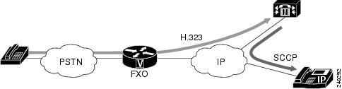
The connection plar opx immediate option enables FXO ports to set up calls with no ring discrepancy for Caller ID between the caller and the called party. To implement the FXO Delayed Caller ID Delivery feature, you must have a configured network with a Cisco 2800 or Cisco 3800 series integrated services router running Cisco IOS Release 12.4(11)XW. The integrated services router must have at least one voice interface card. Cisco CallManager Release 4.2.3 SR1 or later releases must be installed on the network to support this feature.
Figure 3 and Figure 4 show the network topology and call flow for the FXO Delayed Caller ID feature. The caller is in the PSTN, and the call arrives via an FXO port at the gateway. In Figure 3, the gateway is connected via H.323 to Cisco CallManager. Cisco CallManager extends the call to the called party which is a SCCP-based IP phone (Cisco 7941).
Figure 3
Network Topology for the FXO Delayed Caller ID Delivery Feature
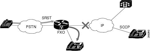
In Figure 4, the gateway is on the same router, and Survivable Remote Site Telephony (SRST) is active. SRST extends the call to the called party, which is a Skinny Client Control Protocol (SCCP)-based IP phone (Cisco 7941).
Figure 4
Network Topology for the FXO Delayed Caller ID Delivery Feature (using SRST)
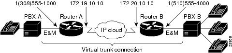
Use the connection trunk command to specify a permanent tie-line connection to a PBX. VoIP simulates a trunk connection by creating virtual trunk tie lines between PBXs connected to Cisco devices on each side of a VoIP connection (see Figure 5). In this example, two PBXs are connected using a virtual trunk. PBX-A is connected to Router A via an E&M voice port; PBX-B is connected to Router B via an E&M voice port. The Cisco routers spoof the connected PBXs into believing that a permanent trunk tie line exists between them.
Figure 5 Virtual Trunk Connection
In configuring virtual trunk connections in VoIP, the following restrictions apply:
•
–
–
–
•
•
Note
To configure one of the devices in the trunk connection to act as slave and only receive calls, use the answer-mode option with the connection trunk command when configuring that device.
Note
VoIP establishes the trunk connection immediately after configuration. Both ports on either end of the connection are dedicated until you disable trunking for that connection. If for some reason the link between the two switching systems goes down, the virtual trunk reestablishes itself after the link comes back up.
Use the connection tie-line command when the dial plan requires you to add additional digits in front of any digits dialed by the PBX, and the combined set of digits is used to route the call onto the network. The operation is similar to the connection plar command operation, but in this case, the tie-line port waits to collect thedigits from the PBX. Tie-line digits are automatically stripped by a terminating port.
Examples
The following example shows PLAR as the connection mode with a destination telephone number of 555-0100:
voice-port 1/0/0connection trunk 5550100The following example shows the tie-line as the connection mode with a destination telephone number of 555-0100:
voice-port 1/1connection tie-line 5550100The following example shows a PLAR off-premises extension connection with a destination telephone number of 555-0100:
voice-port 1/0/0connection plar-opx 5550100The following example shows a trunk connection configuration that is established only when the trunk receives an incoming call:
voice-port 1/0/0connection trunk 5550100 answer-modeThe following example shows a PLAR off-premises extension connection with a destination telephone number of 0199. The router waits for the off-hook signal before cutting through the audio path.
voice-port 2/0/0connection plar opx 0199 cut-through-waitThe following examples show configuration of the routers on both sides of a VoIP connection (as illustrated in Figure 5) to support trunk connections.
Router A
voice-port 1/0/0connection trunk +15105550190dial-peer voice 10 potsdestination-pattern +13085550181port 1/0/0dial-peer voice 100 voipsession-target ipv4:172.20.10.10destination-pattern +15105550190Router B
voice-port 1/0/0connection trunk +13085550180dial-peer voice 20 potsdestination-pattern +15105550191port 1/0/0dial-peer voice 200 voipsession-target ipv4:172.19.10.10destination-pattern +13085550180Related Commands
connection-timeout
To configure the time in seconds for which a connection is maintained after completion of a communication exchange, use the connection-timeout command in settlement configuration mode. To return to the default value, use the no form of this command.
connection-timeout seconds
no connection-timeout seconds
Syntax Description
Command Default
3600 seconds (1 hour)
Command Modes
Settlement configuration
Command History
12.0(4)XH1
This command was introduced on the Cisco 2600 series, Cisco 3600 series and Cisco AS5300.
12.0(7)T
This command was integrated into Cisco IOS Release 12.0(7)T.
Usage Guidelines
The router maintains the connection for the configured period in anticipation of future communication exchanges to the same server.
Examples
The following example shows a connection configured to be maintained for 3600 seconds after completion of a communications exchange:
settlement 0connection-timeout 3600Related Commands
copy flash vfc
To copy a new version of VCWare from the Cisco AS5300 universal access server motherboard to voice feature card (VFC) Flash memory, use the copy flash vfc command in privileged EXEC mode.
copy flash vfc slot-number
Syntax Description
Command Modes
Privileged EXEC
Command History
Usage Guidelines
Use the copy flash vfc command to use the standard copy user interface in order to copy a new version of VCWare from the Cisco AS5300 universal access server motherboard to VFC Flash memory. The VFC is a plug-in feature card for the Cisco AS5300 universal access server and has its own Flash memory storage for embedded firmware. For more information about VFCs, refer to Voice-over-IP Card.
Once the VCWare file has been copied, use the unbundle vfc command to uncompress and install VCWare.
Examples
The following example copies a new version of VCWare from the Cisco AS5300 universal access server motherboard to VFC Flash memory:
Router# copy flash vfc 0Related Commands
copy tftp vfc
Copies a new version of VCWare from a TFTP server to VFC Flash memory.
unbundle vfc
Unbundles the current running image of VCWare or DSPWare into separate files.
copy tftp vfc
To copy a new version of VCWare from a TFTP server to voice feature card (VFC) Flash memory, use the copy tftp vfc command in privileged EXEC mode.
copy tftp vfc slot-number
Syntax Description
slot-number
Slot on the Cisco AS5300 in which the VFC is installed. Range is from 0 to 2. There is no default.
Command Default
No default behavior or values
Command Modes
Privileged EXEC
Command History
Usage Guidelines
Use the copy tftp vfc command to copy a new version of VCWare from a TFTP server to VFC Flash memory. The VFC is a plug-in feature card for the Cisco AS5300 universal access server and has its own Flash storage for embedded firmware. For more information about VFCs, refer to Voice-over-IP Card.
Once the VCWare file has been copied, use the unbundle vfc command to uncompress and install VCWare.
Examples
The following example copies a file from the TFTP server to VFC Flash memory:
Router# copy tftp vfc 0Related Commands
corlist incoming
To specify the class of restrictions (COR) list to be used when a specified dial peer acts as the incoming dial peer, use the corlist incoming command in dial peer configuration mode. To clear the previously defined incoming COR list in preparation for redefining the incoming COR list, use the no form of this command.
corlist incoming cor-list-name
no corlist incoming cor-list-name
Syntax Description
cor-list-name
Name of the dial peer COR list that defines the capabilities that the specified dial peer has when it is used as an incoming dial peer.
Command Default
No default behavior or values.
Command Modes
Dial peer configuration
Command History
Usage Guidelines
The dial-peer cor list and member commands define a set of capabilities (a COR list). These lists are used in dial peers to indicate the capability set that a dial peer has when it is used as an incoming dial peer (the corlist incoming command) or to indicate the capability set that is required for an incoming dial peer to make an outgoing call through the dial peer (the corlist outgoing command). For example, if dial peer 100 is the incoming dial peer and its incoming COR list name is list_100, dial peer 200 has list_200 as the outgoing COR list name. If list_100 does not include all the members of list_200 (that is, if list_100 is not a superset of list_200), it is not possible to have a call from dial peer 100 that uses dial peer 200 as the outgoing dial peer.
Examples
In the following example, incoming calls from 526.... are blocked from being switched to outgoing calls to 1900.... because the COR list for the incoming dial peer (list2) is not a superset of the COR list for the outgoing dial peer (list1):
dial-peer list list1member 900_calldial-peer list list2member 800_callmember other_calldial-peer voice 526 potsanswer-address 408526....corlist incoming list2direct-inward-dialdial-peer voice 900 potsdestination pattern 1900.......direct-inward-dialtrunkgroup 101prefix 333corlist outgoing list1Related Commands
corlist outgoing
Specifies the COR list to be used by outgoing dial peers.
dial-peer cor list
Defines a COR list name.
member
Adds a member to a dial peer COR list.
corlist outgoing
To specify the class of restrictions (COR) list to be used by outgoing dial peers, use the corlist outgoing command in dial peer configuration mode. To clear the previously defined outgoing COR list in preparation for redefining the outgoing COR list, use the no form of this command.
corlist outgoing cor-list-name
no corlist outgoing cor-list-name
Syntax Description
cor-list-name
Required name of the dial peer COR list for outgoing calls to the configured number using this dial peer.
Command Default
No default behavior or values.
Command Modes
Dial peer configuration
Command History
Usage Guidelines
If the COR list for the incoming dial peer is not a superset of the COR list for the outgoing dial peer, calls from the incoming dial peer cannot use that outgoing dial peer.
Examples
In the following example, incoming calls from 526.... are blocked from being switched to outgoing calls to 1900.... because the COR list for the incoming dial peer (list2) is not a superset of the COR list for the outgoing dial peer (list1):
dial-peer list list1member 900_calldial-peer list list2member 800_callmember other_calldial-peer voice 526 potsanswer-address 408526....corlist incoming list2direct-inward-dialdial-peer voice 900 potsdestination pattern 1900.......direct-inward-dialtrunk group 101prefix 333corlist outgoing list1cptone
To specify a regional analog voice-interface-related tone, ring, and cadence setting, use the cptone command in voice-port configuration mode. To disable the selected tone, use the no form of this command.
cptone {locale}
no cptone {locale}
Syntax Description
locale
Voice-interface-related default tone, ring, and cadence setting for a specified country (for ISDN PRI and E1 R2 signaling). Keywords are shown in Table 14 and Table 15. The default keyword is us in Cisco IOS Release 12.0(4)T and later.
Command Default
The default keyword is us for all supported gateways and interfaces in Cisco IOS Release 12.0(4)T and later.
Command Modes
Voice-port configuration
Command History
Usage Guidelines
This command defines the detection of call-progress tones generated at the local interface. It does not affect any information passed to the remote end of a connection, and it does not define the detection of tones generated at the remote end of a connection. Use the cptone command to specify a regional analog voice interface-related default tone, ring, and cadence setting for a specified voice port.
If your device is configured to support E1 R2 signaling, the E1 R2 signaling type (whether ITU, ITU variant, or local variant as defined by the cas-custom command) must match the appropriate pulse code modulation (PCM) encoding type as defined by the cptone command. For countries for which a cptone value has not yet been defined, you can try the following:
•
•
Table 14 lists valid entries for the locale argument.
Table 14 Valid Command Entries for locale Argument
Argentina
ar
Lebanon
lb
Australia
au
Luxembourg
lu
Austria
at
Malaysia
my
Belgium
be
Mexico
mx
Brazil
br
Nepal
np
Custom 11
c1
Netherlands
nl
Custom 21
c2
New Zealand
nz
Canada
ca
Nigeria
ng
China
cn
Norway
no
Colombia
co
Pakistan
pk
Czech Republic
cz
Panama
pa
Denmark
dk
Peru
pe
Egypt
eg
Philippines
ph
Finland
fi
Poland
pl
France
fr
Portugal
pt
Germany
de
Russian Federation
ru
Ghana
gh
Saudi Arabia
sa
Great Britain
gb
Singapore
sg
Greece
gr
Slovakia
sk
Hong Kong
hk
Slovenia
si
Hungary
hu
South Africa
za
Iceland
is
Spain
es
India
in
Sweden
se
Indonesia
id
Switzerland
ch
Ireland
ie
Taiwan
tw
Israel
il
Thailand
th
Italy
it
Turkey
tr
Japan
jp
United States
us
Jordan
jo
Venezuela
ve
Kenya
ke
Zimbabwe
zw
Korea Republic
kr
1 Automatically configured the first time the XML file is downloaded to the gateway.
Table 15 describes the locale keywords for ISDN PRI signaling.
Examples
The following example configures United States as the call-progress tone locale beginning in global configuration mode:
voice-port 1/0/0cptone usThe following example configures Brazil as the call-progress tone locale on a Cisco universal access server:
voice-port 1:0cptone BRdescription Brasil ToneRelated Commands
credential load
To reload a credential file into flash memory, use the credential load command in privileged EXEC mode.
credential load tag
Syntax Description
tag
Number that identifies the credential (.csv) file to load. Range: 1 to 5. This is the number that was defined with the authenticate credential command.
Command Default
The credential file is not reloaded.
Command Modes
Privileged EXEC
Command History
12.4(11)XJ
This command was introduced.
12.4(15)T
This command was integrated into Cisco IOS Release 12.4(15)T.
Usage Guidelines
This command provides a shortcut to reload credential files that were defined with the authenticate credential command.
Up to five .csv files can be configured and loaded into the system. The contents of these five files are mutually exclusive, that is, the username/password pairs must be unique across all the files. For Cisco Unified CME, these username/password pairs cannot be the same ones defined for SCCP or SIP phones with the username command.
Examples
The following example shows how to reload credential file 3:
credential load 3Related Commands