Downloads |
 Feedback Feedback
|
Table Of Contents
Determining Platform Support Through Cisco Feature Navigator
Availability of Cisco IOS Software Images
Restrictions for RPR+ for the Cisco AS5850
Route Switch Controller Restrictions
Configuration Mode Restrictions
Universal Gateway Restrictions
Route Processor Redundancy Plus (RPR+)
Bulk Synchronization During Initialization
HA-Aware Protocols and Applications
How to Configure RPR+ for the Cisco AS5850
Fast Software Upgrade in RPR+ Mode
Fast Software Upgrade Procedure
show monitor event-trace redundancy
show monitor event-trace reconciliation
RPR+ for the Cisco AS5850
ContentsRPR+ and IOS
Route Processor Redundancy Plus (RPR+) for the Cisco AS5850 is an incremental step within an overall program to provide higher availability of Cisco IOS software on the Cisco AS5850. RPR+ provides protection for network edge devices with redundant RSCs that represent a single point of failure in the network design, and where an outage might result in loss of service for customers.
Feature Specifications for RPR+ for the Cisco AS5850
12.3(2)T
This feature was introduced on the Cisco AS5850.
Cisco AS5850
Determining Platform Support Through Cisco Feature Navigator
Cisco IOS software is packaged in feature sets that are supported on specific platforms. To get updated information regarding platform support for this feature, access Cisco Feature Navigator. Cisco Feature Navigator dynamically updates the list of supported platforms as new platform support is added for the feature.
Cisco Feature Navigator is a web-based tool that enables you to determine which Cisco IOS software images support a specific set of features and which features are supported in a specific Cisco IOS image. You can search by feature or release. Under the release section, you can compare releases side by side to display both the features unique to each software release and the features in common.
To access Cisco Feature Navigator, you must have an account on Cisco.com. If you have forgotten or lost your account information, send a blank e-mail to cco-locksmith@cisco.com. An automatic check will verify that your e-mail address is registered with Cisco.com. If the check is successful, account details with a new random password will be e-mailed to you. Qualified users can establish an account on Cisco.com by following the directions found at this URL:
Cisco Feature Navigator is updated regularly when major Cisco IOS software releases and technology releases occur. For the most current information, go to the Cisco Feature Navigator home page at the following URL:
Availability of Cisco IOS Software Images
Platform support for particular Cisco IOS software releases is dependent on the availability of the software images for those platforms. Software images for some platforms may be deferred, delayed, or changed without prior notice. For updated information about platform support and availability of software images for each Cisco IOS software release, refer to the online release notes or, if supported, Cisco Feature Navigator.
Restrictions for RPR+ for the Cisco AS5850
General Restrictions
The two (redundant) Route Switch Controllers (RSCs) that are installed in the chassis must be of the same type, both must be Enhanced Route Switch Controllers (eRSCs), and both must be running the same version of the Cisco IOS software:
•
Cisco IOS Release 12.3(2)T or later release
If the RSCs are operating different Cisco IOS images, the system reverts to RPR mode even if RPR+ is configured.
Configuration changes made through Simple Network Management Protocol (SNMP) may not be automatically configured on the standby RSC after a switchover occurs.
Route Switch Controller Restrictions
RSC (Route Switch Controller) is the generic term for the route processor and can refer to either the RSC-1 or the eRSC.
eRSC (Enhanced Route Switch Controller) refers to the enhanced, next generation route processor.
RSC-1 (Route Switch Controller One) refers to the original version of the route processor.
Note
Note
Note
Configuration Mode Restrictions
The following configuration mode restrictions apply to the RPR+.
•
Config mode locked out until standby initializes•
Universal Gateway Restrictions
If a switchover occurs before the standby RSC is fully initialized, the switchover results in both RSCs being reloaded and all feature cards being reset.
RPR+ Overview
The Cisco AS5850 uses dual enhanced route switch controllers (eRSCs) with RPR+ to increase network availability.
Note
RPR+ takes advantage of redundancy by establishing one of the RSCs as the active processor while the other RSC is designated as the standby processor. Following an initial synchronization between the active and standby RSCs, RPR+ dynamically maintains configuration information between the two RSCs. This means that the standby RSC need not be reloaded and reinitialized, and the feature cards are not reset if the active RSC fails.
A switchover from the active to the standby processor occurs when the active RSC fails due to a catastrophic hardware or software failure. All active calls are dropped when a switchover occurs. After the switchover, new calls are accepted in less than one second plus the route convergence time.
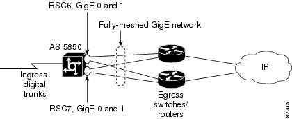
Figure 1 illustrates how RPR+ is typically deployed in service provider networks. In this example, each RSC is connected to the internal network through both of its Gigabit Ethernet interfaces. This redundancy is complemented by RPR+. While one RSC is processing calls, the other is identically configured and waiting to take over. This fast switchover takes seconds and ensures the highest availability.
The active RSC controls the interfaces of the standby RSC. This includes the Gigabit Ethernet and Fast Ethernet interfaces. Load sharing is supported across all of the egress interfaces. Traffic on the standby RSC Fast Ethernet interface is sent to the CPU on the active RSC. The standby RSC Fast Ethernet interface should only be used for network management purposes.
Note
Figure 1 RPR+ Network Deployment—Service Provider Network
Redundancy Modes
RPR+ is the next level of high availability (HA) for the Cisco AS5850. Cisco AS5850 redundancy modes are described in the following sections:
•
Route Processor Redundancy Plus (RPR+)
In RPR+ mode, the standby RSC is fully initialized. The startup configuration is read, and the active RSC dynamically synchronizes startup and running configuration changes to the standby RSC. This means that the standby RSC need not be reloaded and reinitialized, and the feature cards are not reset if the active RSC fails. Information synchronized to the standby RSC includes startup and running configuration information and changes to the chassis state such as online insertion and removal (OIR) of hardware. After switchover, new calls are being accepted in less than one second plus route convergence time.
Handover-Split Mode
Handover-split mode maximizes system availability by allowing an RSC to automatically take control of the slots and cards managed by the other RSC when it fails. Each RSC is configured identically as appropriate for the full set of cards. During normal operation, both RSCs are active, handling their own slots, cards, and calls just as in classic-split mode. Should an RSC fail, the other RSC takes over control of the failed RSC's slots, goes into extra-load state, restarts the failed RSC's cards, and handles newly arrived calls on those cards—although calls on the failed RSC are lost at the moment of failure.
Note
Classic-Split Mode
Classic-split mode (the default) maximizes system throughput by splitting slots between two RSCs. Each RSC controls a certain set of slots (slots 0-5 are owned by the RSC in slot 6 and slots 8-13 are owned by the RSC in slot 7) and operates as though slots other than those that it controls contain no cards, because those cards are controlled by the other RSC. Configuration on each RSC effects only the slots owned by that RSC. Calls on a failed RSC are lost, but calls on the functioning RSC continue normally. Operating a Cisco AS5850 in classic-split mode is the same as having two Cisco AS5850s, each with a separate set of cards.
Note
Synchronization
Synchronization occurs in two separate phases:
•
Bulk Synchronization During Initialization
When the Cisco AS5850 is powered up, the active RSC performs a chassis discovery (discovery of the number and type of feature cards in the system) and parses the startup configuration file. The active RSC owns all the resources for the chassis, including the interfaces on the standby RSC.
The active RSC then synchronizes this data to the standby RSC and instructs the standby RSC to complete its initialization. This method ensures that both RSCs contain the same configuration information.
Note
Checkpoint Facility (CF)
The collection of important state information is made possible by the checkpoint facility (CF) subsystem within the Cisco IOS software. Information for call and chassis configuration states must be maintained on the standby RSC in the event of a switchover. Checkpoint clients register with the CF and update the standby RSC with any state changes.
Synchronization of Startup Configuration
The startup configuration is a text file stored in the NVRAM of the RSC. During system startup, the startup configuration file is copied from the active RSC to the standby RSC. Any existing startup configuration file on the standby RSC is overwritten.
The startup configuration file is also synchronized whenever you perform the following operations:
•
•
•
•
•
•
•
Incremental Synchronization
After both RSCs are fully initialized, any further changes to the running configuration or active call states are synchronized to the standby RSC. Active call states are updated as a result of processing protocol information, external events (such as the interface becoming up or down), user configuration commands, or other internal events.
CLI Commands
CLI changes to the running configuration are synchronized from the active RSC to the standby RSC. In effect, the CLI command is automatically updated on the standby RSC when run on the active RSC.
SNMP SET Commands
Configuration changes caused by an SNMP SET command are synchronized on a case-by-case basis. Currently only two SNMP configuration SETs are supported:
•
•
Routing and Forwarding Information
State changes for high availability (HA)-aware protocols or applications (SNMP) are synchronized to the standby RSC.
Chassis State
Changes to the chassis state due to feature card insertion or removal are synchronized to the standby RSC.
Feature Card State
Changes to the feature card states are synchronized to the standby RSC. Feature card state information is initially obtained during bulk synchronization of the standby RSC. Following bulk synchronization, feature card events, such as whether the interface is up or down, are received at the active RSC and synchronized to the standby RSC.
Counters and Statistics
The various counters and statistics maintained in the active RSC are not synchronized, because they may change often and the degree of synchronization they require is substantial. The volume of information associated with statistics makes synchronizing them impractical.
Note
Switchover Operation
During switchover, system control and routing protocol execution are transferred from the active RSC to the standby RSC. Switchover may be due to a manual operation (CLI-invoked) or to a software- or hardware-initiated operation (hardware or software fault induced).
RSC Removal
Before removing an RSC, check to make sure that the RSC is NOT the primary-TDM-clock provider for the system. Look at the CLK LED on the front panel or use the show chassis clocks command. If the CLK LED on the front panel is on, the RSC is the primary-TDM-clock provider.
Caution
You can force the peer RSC to become the primary-TDM-clock provider by using the push buttons on the front panel or by issuing the hw-module slot n tdm-clock stop command.
Online Insertion and Removal of the Active RSC
Online insertion and removal (OIR) of the active RSC is not supported. Removing the active RSC from the Cisco AS5850 requires a manual switchover from the active to the standby RSC. To remove the active RSC, first switch the active RSC to the standby RSC with the redundancy switch-activity command. After the switchover, the standby RSC is put in maintenance mode for removal. To put the system in maintenance mode, use the maintenance-mode command on the active RSC. This command stops synchronization between the active and standby RSCs and allows you to remove the standby RSC.
Flash File System
The contents of flash and bootflash memory are not automatically synchronized from the active RSC to the standby RSC. Synchronization of the flash and bootflash file systems is the responsibility of the user.
Caution
You can use the following commands to synchronize the flash files:
•
•
If the flash files are not kept synchronized and files that are required for operation are missing, problems are likely to occur after a switchover which may not be immediately apparent. For example, if there is an "override SPE portware" stored in flash and this has not been copied to the standby RSC, the new active RSC will not be able to download the correct SPE portware after a switchover, should one be required in the future.
Switchover Conditions
A switchover may occur under the following conditions:
•
–
–
•
•
The user can force the switchover from the active RSC to the standby RSC by using a CLI command. This manual procedure allows for a graceful or controlled shutdown of the active RSC and switchover to the standby RSC. This graceful shutdown allows critical cleanup to occur.
Note
Switchover Reason
If the active RSC is reset and a switchover occurs, run the show redundancy history and show redundancy switchover history commands to display a log of high availability (HA) events. This will give you clues as to why a switchover or other event occurred. Also, if the Health Monitor is responsible for initiating the switchover, the output of the show monitor event-trace hm command will outline why this occurred.
Switchover Time
The time required for a switchover from the active RSC to the standby RSC depends on the number of calls and the types of calls. It is approximately one second plus route convergence time.
Although the newly active RSC takes over almost immediately following a switchover, the time required for the Cisco AS5850 to begin operating again in full redundancy mode can be much longer. This can be due to a number of factors:
•
•
Route Convergence
Route convergence time depends on the routing protocol, the size of the network, and the design of the network. Users should plan and design their networks to minimize convergence time.
Note
One option for minimizing route convergence time is to use low cost static routes. Low cost static routes have a low weighting such that they are used only until the routing protocol converges. This allows new calls to be accepted and external servers to be communicated with directly after a switchover rather than waiting until all routes converge, which may take several seconds or minutes.
When using this approach, static routes to external servers must be entered manually on the AS5850. On routers connected to the AS5850, static routes must be entered manually for the AS5850 loopback addresses and for the IP pool addresses that are used by the AS5850.
Resource Recovery
Resource recovery is the cleaning up process that occurs after a switchover so that resources used by calls that have been cleared during the switchover can be reused for new calls after the switchover.
In RPR+ mode, all active calls are cleared whenever a switchover occurs. Active calls are defined as calls that are in any phase of call set-up, steady state, or call teardown.
The resource recovery process runs on the new active RSC immediately following a switchover and may continue for several seconds. If new calls are received while resource recovery is in progress, the new calls may be rejected until resources become available again.
Most resource recoveries are initiated by the RSC. However, feature boards can also initiate resource recoveries. Various methods are used to achieve resource recovery. For example:
•
•
•
The following external entities may also be involved in resource recovery:
•
•
•
•
Reconciliation
After a switchover, the new active RSC performs reconciliation as described in this section.
Reconciliation is performed when the states of two or more entities in the system are inconsistent. In such cases, these states are examined and rectified.
After a switchover some states may be inconsistent with other states, either on a single node (within the RSC) or across multiple nodes (between the RSC and feature boards).
Inconsistency of states can occur after a hardware or software failure either because a checkpoint message from the active RSC to the standby RSC was lost or a control message between the RSC and a feature board was lost. In these cases, post switchover recovery cannot prevent inconsistency of states.
To see a count of how many resources (such as slots, SPEs, ports) required reconciliation in the previous switchover, use the show redundancy switchover reconciliation command.
To see which resources were modified as a result of reconciliation in the previous switchover, use the show monitor event-trace reconciliation command.
Loopback Interfaces
When an external device configures an interface to the AS5850, it should use a loopback interface instead of a physical interface.
If an external device maps a physical interface to the AS5850 instead of loopback interface, the physical interface will not be available after a switchover or after the RSC is replaced due to a hardware failure and problems will not be detected until after a switchover or replacement occurs.
Caution
HA-Aware Protocols and Applications
High availability (HA) supported protocols and applications must be HA-aware. A feature or protocol is HA-aware if it maintains, either partially or completely, undisturbed operation through an RSC switchover. State information for HA-aware protocols and applications is synchronized, through a process called checkpointing, between the active and standby RSCs. Use the show checkpoint command to see which protocols are HA-aware.
HA-aware applications are either platform-independent, as in the case of line protocols, or platform-dependent, as in the case of feature card drivers.
Line Protocols
HA-aware line protocols synchronize session state information between the active and standby RSCs to keep session information current for a particular interface. In the event of a switchover, session information need not be renegotiated with the peer. During a switchover, HA-aware protocols also check the feature card state to learn if it matches the session state information. HA-aware protocols use the feature card interface to exchange messages with network peers in an effort to maintain network connectivity.
Feature Card Drivers
Platform-specific feature card device drivers are bundled with the Cisco IOS software image for RPR+.
Feature cards used with the RPR+ feature periodically generate status events that are forwarded to the active RSC. Status events enable RPR+ to support bulk synchronization after the standby RSC is initialized and are used for state reconciliation and verification after a switchover.
Feature cards used with the RPR+ feature must adhere to the following requirements:
•
•
•
Caution
Note
Network Management
The AS5850 in RPR+ mode provides a single point of management. The network management station should be configured to poll the loopback interfaces of the AS5850 instead of the physical interfaces so that connectivity remains after switchover.
Network management support for RPR+ is provided through the synchronization of specific SNMP data between the active and standby RSCs. From a network management perspective, this functionality helps to provide an uninterrupted management interface to the network administrator.
Note
Benefits
Improved Network Availability
•
Because RPR+ maintains protocol and application state information, configuration information is maintained after a switchover. This allows the feature cards to accept new calls immediately after the RSC switchover.
•
RPR+ provides a faster switchover by fully initializing and configuring the standby RSC and by synchronizing state information, which can reduce the time required for routing protocols to converge. After a switchover, new calls are accepted in less than one second plus route convergence time.
•
If an RSC fails, the system continues to operate normally until there is time to replace the failed RSC.
Front Panel Display
Table 1 shows the names and descriptions of the RSC front panel alphanumeric display labels and their descriptions.
How to Configure RPR+ for the Cisco AS5850
This section contains the following procedures. Each task in the list is identified as either required or optional.
•
•
•
Fast Software Upgrade in RPR+ Mode
You can upgrade the Cisco IOS image using the fast software upgrade (FSU) if both RSCs are already running RPR+ aware images. During the FSU, the standby RSC is upgraded first and when the active RSC is upgraded, the standby RSC continues to process all the calls coming into the Cisco AS5850.
Power Cycle Chassis
The first time that you load an RPR+ enabled software image onto an AS5850, you should power cycle the chassis to download the new MBUS firmware. Without a power cycle, the MBUS temperature diagnostics will not function and the alphanumeric display on the front panel will display the wrong information.
Note
Fast Software Upgrade Procedure
The following procedure copies a new IOS image into Flash memory. The RSC can than load the image from Flash memory. You can also load the image from a TFTP server.
Summary Steps
Follow these steps to upgrade the IOS images for both RSCs:
1.
2.
3.
4.
5.
6.
7.
8.
9.
Detailed Steps
Configuring RPR+
Configuring RPR+ is a two-step process. Perform the following procedures to configure RPR+:
Caution
Changing the Redundancy Mode
To change the redundancy mode, perform the following steps:
Caution
Summary Steps
1.
2.
3.
4.
5.
6.
Detailed Steps
Updating the Configuration
If you are upgrading from classic-split or handover-split mode, the configuration must be updated to include the configuration for the cards previously owned by the other RSC. The changes necessary include:
•
•
Note
•
After the configuration changes have been made, save the changes and reboot the universal gateway:
Summary Steps
1.
2.
3.
Detail Steps
Enabling the Standby Console
The console port on the standby RSC is disabled by default. To enable the standby console, follow these steps:
Summary Steps
1.
2.
3.
Detail Steps
Troubleshooting Tips
•
To display a log of HA events and clues as to why a switchover or other event occurred, enter the show redundancy history and show redundancy switchover history commands.
If the switchover was initiated by the Health Monitor, the output of the show monitor event-trace hm command on the new active RSC should display the reason why the switchover occurred.
•
The output of the show redundancy states command displays the actual operating redundancy mode running on the device, and not the configured mode as set on the RSC. The operating mode of the system can change depending on system events. For example, RPR+ requires that both RSCs be running the same software image; if the images are different, the device does not operate in RPR+ mode, regardless of its configuration.
•
The RPR+ feature introduces a number of commands, including commands to manually cause a switchover (redundancy switch-activity.) The reload command is not an RPR+ command. This command causes a full reload of the system, removing all table entries, resetting all feature cards, and thereby interrupting network traffic forwarding.
•
First, check to make sure that the RSC to be removed is NOT the primary TDM clock provider. If it is, reassign the TDM clock to another source before removing the RSC (see RSC Removal for details).
To put the standby RSC in maintenance mode, use the maintenance-mode command in redundancy configuration mode. This command stops synchronization between the active and standby RSCs and allows you to remove the standby RSC. To remove the active RSC, first switch the active RSC to the standby RSC using the redundancy switch-activity command.
•
To learn about platform redundancy events such as boot time negotiation, arbitration, HA line states, RF state transitions and some Enhanced High System Availability (EHSA) events, use the show monitor event-trace redundancy command.
•
To see what checkpointing clients are active, use the show checkpoint command.
•
The AAA server needs to be set with the network access server (NAS) loopback address rather than the IP address from one of the physical interfaces. Additionally the following command needs to be configured:
ip radius source-interface Loopback 0
OR
ip tacacs source-interface Loopback 0
•
Ensure you can still reach the destination router and you will need the following command on the Loopback interface:
interface loopback0
 ip address 192.168.201.1 255.255.255.0
 h323-gateway voip bind srcaddr 192.168.201.1

For SIP the following should be set:

voice service voip
 sip
  bind all source-interface Loopback0
You can also use the mgcp bind command to ensure that MGCP (Media Gateway Control Protocol) calls continue functioning after a switchover:
Router>enableRouter#configure terminalRouter(config)#mgcp bind {control | media} source interface <loopback interface>Router(config)#mgcpRouter(config)#exitRouter#Configuration Examples
This section provides the following configuration examples:
Configuring RPR+ Example
In the following example, the active RSC is in slot 6 and the standby RSC is installed in slot 7 of a Cisco AS5850:
Router#busyout slot-numberRouter#configure terminalRouter(config)#redundancyRouter(config-red)#mode rpr-plusRouter(config-red)#endRouter#copy running-config startup-configRouter#reloadAdditional References
For additional information related to RPR+ for the Cisco AS5850, refer to the following references:
Related Documents
Standards
MIBs
To locate and download MIBs for selected platforms, Cisco IOS releases, and feature sets, use Cisco MIB Locator found at the following URL:
http://tools.cisco.com/ITDIT/MIBS/servlet/index
If Cisco MIB Locator does not support the MIB information that you need, you can also obtain a list of supported MIBs and download MIBs from the Cisco MIBs page at the following URL:
http://www.cisco.com/public/sw-center/netmgmt/cmtk/mibs.shtml
To access Cisco MIB Locator, you must have an account on Cisco.com. If you have forgotten or lost your account information, send a blank e-mail to cco-locksmith@cisco.com. An automatic check will verify that your e-mail address is registered with Cisco.com. If the check is successful, account details with a new random password will be e-mailed to you. Qualified users can establish an account on Cisco.com by following the directions found at this URL:
RFCs
Technical Assistance
New and Modified Commands
This section describes the new and modified RPR+ commands. All other commands used with this feature are documented in the Cisco IOS High Availability command reference publications for various releases.
•
•
•
show chassis
To display processor and memory information, use the show chassis command in EXEC mode.
show chassis [ clocks | slot ]
Syntax Description
Defaults
No default behavior or values.
Command Modes
EXEC
Command History
12.2(2)XB1
This command was introduced on the Cisco AS5850.
12.3(2)T
This command was modified for Route Processor Redundancy Plus (RPR+) on the Cisco AS5850.
Usage Guidelines
You must enter this command from one of the Route Switch Controllers (RSCs).
Examples
The following example shows output for a system in RPR+ mode:
Router#show chassisSlot Board CPU Proc Memory I/O Memory State ElapsedType Util Total (free) Total (free) Time3 CT3_UP216 0%/0% 59296736( 67%) 67108864( 73%) IOS up 08:01:176 RSC 0%/0% 160531232( 69%) 67108864( 88%) IOS up 08:02:367 RSC 0%/0% 160531232( 69%) 67108864( 88%) IOS up 08:02:0812 8E1_UP216 0%/0% 59296736( 68%) 67108864( 73%) IOS up 08:01:17
The following example shows details for the card in slot 0:
Router#show chassis slot 0Slot: 0, Type: 24 E1 Ports (700)CPU utililization: 0%/0% (5 secs); 0% (1 min); 0% (5 mins)Memory: Total(b) Used(b) Free(b) Lowest(b) Largest(b)Processor 59304928 16307688 42997240 42817836 42819352I/O 67108864 8200288 58908576 58515056 58515004State: IOS up; elapsed time in state: 13:28:35Flags:FB_FLAGS_PRESENTFB_FLAGS_LINECARDFB_FLAGS_ANALYZEDFB_FLAGS_CHECKPOINTInserted: 13:39:30 agoLast update: 00:00:08 agoRelated Commands
show redundancy
To display current or historical status and related redundancy information, use the show redundancy command in EXEC mode.
show redundancy [clients | counters | history | states | switchover {history | reconciliation}]
Syntax Description
Defaults
No default behavior or values.
Command Modes
EXEC
Command History
11.3(6)AA
This command was introduced.
12.2(2)XB1
This command was enhanced for the Cisco AS5850.
12.3(2)T
This command was enhanced for RPR+ on the Cisco AS5850.
Usage Guidelines
You must have two route-switch-controller (RSC) cards installed on your Cisco AS5850 and they must have the same RPR+-aware image installed.
Examples
The following example shows the output from the show redundancy, show redundancy states, and show redundancy reconciliation commands:
Router#sh redundancyRSC 6 (This RSC) : ActiveRSC 7 : StandbyRedundancy state is REDUNDANCY_PEERSTANDBY_INITEDUptime since this RSC became active from reload : 14 hours, 59 minutesStandby failures since this RSC active : 4The standby RSC has been up for : 9 minutesStandby RSC information...Standby is up.Standby has 524288K bytes of memory.Standby BOOT variable = tftp:tetryl-config/wollemiRSC6.image 1.0.0.3,12;Standby CONFIG_FILE variable =Standby BOOTLDR variable =Standby Configuration register is 0x2Standby version:Cisco Internetwork Operating System SoftwareIOS (tm) 5850 Software (C5850-P9-M), Experimental Version 12.2(20021029:111439)[phanselm-goliath_hm 129]Copyright (c) 1986-2002 by cisco Systems, Inc.Compiled Thu 31-Oct-02 17:54 by phanselmRouter#show redundancy statesmy state = 13 -ACTIVEpeer state = 8 -STANDBY HOTMode = DuplexUnit = Preferred PrimaryUnit ID = 6Redundancy Mode = Stateful SwitchoverMaintenance Mode = DisabledManual Swact = EnabledCommunications = Upclient count = 35client_notification_TMR = 30000 millisecondskeep_alive TMR = 1000 millisecondskeep_alive count = 0keep_alive threshold = 10RF debug mask = 0x0
Router#show redundancy switchover reconciliationChanges due to reconciliation :Number of slots reconciled for PM DB accounting = 2Number of slots reconciled for PM DB status time out for firmware transfer = 0Number of slots reconciled for PM DB wrong firmware transfer = 0Number of slots reconciled for PM DB with failed firmware transfer = 2Number of slots reconciled for PM DB enable = 0Number of slots reconciled for number of active calls = 0Number of SPEs reconciled due to portware transfer at time of switchover = 0Number of SPEs reconciled due to runtime error = 0Number of SPEs whose states were reconciled = 0Number of slots reconciled for IDB config settings = 0Number of ports reconciled for on hook = 0Number of slots reconciled for country code settings = 0Related Commands
show checkpoint
To see what checkpointing clients are active, use the show checkpoint clients command in privileged EXEC mode.
show checkpoint { clients | statistics }
Syntax Description
clients
Displays a list of clients registered with Checkpoint Facility (CF).
statistics
Displays status information about checkpoint message queue.
Defaults
No default behavior or values.
Command Modes
Privileged EXEC
Command History
Usage Guidelines
Use this command to identify checkpoint clients that appear in error messages.
Examples
The following example shows the output from the show checkpoint clients command:
Router#show checkpoint clientsCheck Point List of ClientsCHKPT on ACTIVE server.Client Name Client ID Msg Send Msg len Bundling(number of) (Total)-----------------------------------------------------------CHKPT DevTest 3 0 0 OnCHKPT EXAMPLE 2 0 0 OnPPP 0 0 0 OnSNMP CF Client 12 18 9266 OffFDM-HA 35 1 4 OnNetwork RF Client 6 19 11040 OffHDLC Pool 33 513 16392 OnRSC Trunk 34 249 5960 OnIP Pool 31 1 8 OnDialer 30 218 6080 OnModem 29 5 52 OnTTY 28 9073 540868 OnVDEV 26 6049 361156 OnNP SSM 25 1729 41476 OnCSM Trunk Mgr 19 2 40 OnCSM 18 1 8 OnRSC TDM 16 5 80 OnSlot CHKPT 15 17 328 OnTSP NP 32 1 4 OnResource Manager 17 1599 63456 OnPM SPE DB 27 1373 60710 On
The following example shows the output from the show checkpoint statistics command:
Router#show checkpoint statisticsCheck Point StatusCHKPT on ACTIVE server.Number of chkpt messages currently in hold queue 0CHKPT MAX MTU size = 1344IPC MAX MTU size = 4096CHKPT Pending msg timer = 100 msRouter#Related Commands
show csm call
To view the call switching module (CSM) call statistics, use the show csm call command in EXEC mode.
show csm call { failed | rate | total }
Syntax Description
Defaults
No default behavior or values.
Command Modes
EXEC
Command History
Usage Guidelines
Use this command to understand CSM call volume.
Examples
The following examples show the CSM call statistics for the last 60 seconds:
Router#show csm call rate1514131211109876 *5 *4 * * * *3 * * ** * * * *** * * * *2 ** * *** * * * ** * ****** ** * * ***1 * ***************** * * ******* *******************0....5....1....1....2....2....3....3....4....4....5....5....0 5 0 5 0 5 0 5 0 5CSM call switching rate per second (last 60 seconds)# = calls entering the module per second1413121110987 *6 * * * *** * * * *5 *** * *** ** * ********* *** * *** *** * ** *** *****4 **********************************************************3 **********************************************************2 **********************************************************1 ##########################################################0....5....1....1....2....2....3....3....4....4....5....5....0 5 0 5 0 5 0 5 0 5CSM call switching rate per second (last 60 minutes)* = maximum calls/s # = average calls/s1514131211109 *8 * *7 * **** *** **6 ****************5 ****************4 ****************3 ****************2 ****************1 ###############*0....5....1....1....2....2....3....3....4....4....5....5....6....6....7.0 5 0 5 0 5 0 5 0 5 0 5 0CSM call switching rate per second (last 72 hours)* = maximum calls/s # = average calls/sRelated Commands
show vdev
For information about the digital signal processors (DSPs) on a specific card, use the show vdev command in privileged EXEC mode.
show vdev {slot/port}
Syntax Description
Defaults
No default behavior or values.
Command Modes
Privileged EXEC
Command History
Usage Guidelines
This command can be used on the standby and active RSC to verify that dynamic and bulk synchronization have been performed correctly on a specified port.
Examples
The following example shows the output for the last port on a 324 universal port card.
Router#show vdev 2/323flags = 0x0000dev_status = 0x0000service = 0x0000service_type = 0x0min_speed = 0, max_speed = 0modulation = 0, err_correction = 0, compression = 0csm_call_info = 0x0, csm_session = Invalidvdev_p set to modem_infoDSPLIB information:dsplib_state = 0x0dsplib_next_action = 0x0HDLC information:call_id = 0x0called_number =speed = 0ces = 0x0spc = FALSEd_idb = 0x0Bulk sync reference = 2, Global bulk syncs = 2
Related Commands
debug vdev
Turns on debugging for voice devices.
show redundancy
Displays current or historical status and related information on a redundant RSC.
show trunk hdlc
To show the state of the HDLC controllers, use the show trunk hdlc command in privileged EXEC mode.
show trunk hdlc { all | ds0| slot number }
Syntax Description
all
Information about all the slots with HDLC controllers.
ds0
Ds0 channel availability.
slot
HDLC information about a specific slot.
number
Trunk card slot number.
Defaults
No default behavior or values.
Command Modes
Privileged EXEC
Command History
Usage Guidelines
The output of the command shows the number of calls on each HDLC controller chip and link. If HDLC calls are failing, this command can help determine if the problem is due to a hardware fault and which controller chip may be responsible.
Examples
The following example displays HDLC controller information for all slots:
Router#show trunk hdlc allHDLC Controller information for slot(s): 0 - 13Slot 3:Sub- HDLC HDLC ctrlrs TDM links (streams): avail DS0s/total DS0sslot Chip Avail Total Link0 Link1 Link2 Link3 Link4 Link5 Link6 Link70 0 128 128 31/31 31/31 31/31 31/31 31/31 31/31 31/31 n/a0 1 128 128 31/31 31/31 31/31 31/31 31/31 31/31 31/31 n/aSlot 12:Sub- HDLC HDLC ctrlrs TDM links (streams): avail DS0s/total DS0sslot Chip Avail Total Link0 Link1 Link2 Link3 Link4 Link5 Link6 Link70 0 124 124 31/31 31/31 31/31 31/31 n/a n/a n/a n/a0 1 124 124 31/31 31/31 31/31 31/31 n/a n/a n/a n/a
Related Commands
show monitor event-trace redundancy
To learn about platform redundancy events such as boot time negotiation, arbitration, high availability line states, redundancy state transitions, and some Enhanced High System Availability (EHSA) events, use the show monitor event-trace redundancy command in privileged EXEC mode.
show monitor event-trace redundancy { all | back | clock | from-boot | latest | parameter }
Syntax Description
Defaults
No default behavior or values.
Command Modes
Privileged EXEC
Command History
Usage Guidelines
Use this command to aid in diagnosing redundancy related issues, such as standby booting failures and standby or active resets.
Note
Examples
The following example shows the redundancy events for the first fifteen minutes after bootup:
Router#show monitor event-trace redundancy clock 00:1552980.996: RF:Peer presence is DOWN52980.996: RF: Power cycle peer RSC52980.996: RF:Peer communications are DOWN52980.996: RF: Power cycle peer RSC52980.996: EHSA: Powercycling peer RSC52981.000: Peer Fatal HA line has been ASSERTED.53091.648: Peer Fatal HA line has been DEASSERTED.53092.120: Arbitration: Received negotiation verification msg via MBUS53092.120: Arbitration: Sent negotiation verification ack msg via MBUS53093.120: EHSA: Received RESTART IPC Bootstrap Message53093.120: EHSA: Sent RESTART ACK IPC Bootstrap Message53093.124: EHSA: Received BOOT IPC Bootstrap Message53093.124: EHSA: Sent BOOT ACK IPC Bootstrap Message53093.192: Received MBUS RF RESTART message53093.196: EHSA: Received INITED IPC Bootstrap Message53093.196: EHSA: Sent INITED ACK IPC Bootstrap Message53094.344: Received MBUS RF RESTART message53095.020: RF:Peer presence is UP53095.020: RF:Peer communications are UP53095.024: RED MODE:sso:RF_PROG_PLATFORM_SYNC:Peer first shows up. Send red mode msg53095.024: RED MODE:sso:Sending redundancy mode to peer53095.024: RF:RF_PROG_PLATFORM_SYNC Progression event53099.156: RF:RF_PROG_STANDBY_CONFIG Progression event53108.764: RF:RF_PROG_STANDBY_FILESYS Progression event53108.764: RF:RF_PROG_STANDBY_BULK Progression event53110.504: RF:RF_PROG_STANDBY_HOT Progression event53320.176: RF:Peer presence is DOWN53320.176: RF: Power cycle peer RSC53320.176: RF:Peer communications are DOWN53320.176: RF: Power cycle peer RSC53320.176: EHSA: Powercycling peer RSC53320.176: Peer Fatal HA line has been ASSERTED.53430.180: Peer Fatal HA line has been DEASSERTED.53430.820: Arbitration: Received negotiation verification msg via MBUS53430.824: Arbitration: Sent negotiation verification ack msg via MBUS53431.824: EHSA: Received RESTART IPC Bootstrap Message53431.824: EHSA: Sent RESTART ACK IPC Bootstrap Message53431.824: EHSA: Received BOOT IPC Bootstrap Message53431.828: EHSA: Sent BOOT ACK IPC Bootstrap Message53431.888: Received MBUS RF RESTART message53431.896: EHSA: Received INITED IPC Bootstrap Message53431.896: EHSA: Sent INITED ACK IPC Bootstrap Message53433.040: Received MBUS RF RESTART message53433.720: RF:Peer presence is UP53433.720: RF:Peer communications are UP53433.720: RED MODE:sso:RF_PROG_PLATFORM_SYNC:Peer first shows up. Send red mode msg53433.720: RED MODE:sso:Sending redundancy mode to peer53433.724: RF:RF_PROG_PLATFORM_SYNC Progression event53437.856: RF:RF_PROG_STANDBY_CONFIG Progression event53447.480: RF:RF_PROG_STANDBY_FILESYS Progression event53447.480: RF:RF_PROG_STANDBY_BULK Progression event53449.220: RF:RF_PROG_STANDBY_HOT Progression event55667.264: RED MODE:SSO:Request to leave this mode55667.264: RED MODE:SSO:Leaving this mode55667.264: RED MODE:rpr-plus:New redundancy mode selected (configured)55667.264: RED MODE:rpr-plus:Sending redundancy mode to peer55667.264: Stopping periodic sending of MBUS RF RESTART messagesRelated Commands
show redundancy history
Displays past status and related information about logged handovers and switchovers.
show monitor event-trace reconciliation
To see which resources were modified as a result of reconciliation in the previous switchover, use the show monitor event-trace reconciliation command in privileged EXEC mode. Since reconciliation takes place on the active RSC directly after switchover this command should be run on the active RSC.
show monitor event-trace reconciliation { all | back | clock | from-boot | latest | parameter }
Syntax Description
Defaults
No default behavior or values.
Command Modes
privileged EXEC
Command History
Usage Guidelines
Use this command to aid in diagnosing post switchover problems. If there are problems with some resources after switchover, run this command on the active RSC to determine whether reconciliation was performed on this resource.
Examples
This example shows the output of this command when run on the new, active RSC after switchover.
Router#show monitor event-trace reconciliation allMar 25 04:24:01: PM DB F/w transfer failed: slot=1 has been changed due to reconciliationMar 25 04:24:01: PM DB F/w transfer failed: slot=9 has been changed due to reconciliationMar 25 04:24:02: PM DB Slot accounting: slot=1 has been changed due to reconciliationMar 25 04:24:02: PM DB Slot accounting: slot=9 has been changed due to reconciliationMar 25 04:24:02: PM DB global accounting: =all has been changed due to reconciliationRelated Commands
show redundancy switchover reconciliation
Displays a count of how many resources required reconciliation in the previous switchover.
show tsp redundancy
To display TSP (Telephony Service Provider) redundancy information related to recovery of TDM DS0 connections on the NP (NextPort), use the show tsp redundancy command. Currently, this command can only be used Service Internal mode.
show tsp {redundancy}
Syntax Description
Defaults
No default behavior or values.
Command Modes
Service Internal
Command History
Usage Guidelines
Use this command to verify that the correct redundancy information is maintained on the standby RSC for switchover recovery of TDM DS0 connections via the TSP NP HA client. No redundancy information is available to show on the active RSC as there is no need to keep the information for switchover recovery on the RSC.
Examples
This example shows the redundancy information maintained on the standby RSC for switchover recovery of TDM DS0 connections via the TSP NP HA client when voice calls are serviced (by the active RSC).
stby-7-Router#show tsp redundancyJun 23 17:22:36.760: TSP NP HA: Queued for recovery TDM trunk to uport conn'n (DS0 2/0:0, uport 0/120)Jun 23 17:22:36.760: TSP NP HA: Queued for recovery TDM trunk to uport conn'n (DS0 2/0:1, uport 0/121)Related Commands
debug tsp redundancy
Debug the TSP NP HA client for switchover redundancy information.
show fdm redundancy
To display information on the forwarding database manager (FDM) which is related to high availability, use the show fdm redundancy command in privileged EXEC mode. This command displays the entries that are populated in the TCAM and also displays for each entry as to whether it is pending removal.
show fdm redundancy
Syntax Description
Defaults
No default values.
Command Modes
Privileged EXEC
Command History
Usage Guidelines
The output of this command is useful in debugging problems after a switchover. Executing this on the new active RSC will display the TCAM entries and whether they are pending removal. Entries pending deletion will typically be non-static routes that existed before the switchover occured. If routing problems occur after a switchover, it will be of interest to run this command and see if a corresponding entry exists in the TCAM or not and whether it is pending removal.
After switchover all calls are dropped, however it may still be possible to receive packets for those dropped calls. Entries may therefore be kept for these in the TCAM for some time (depending on the protocol) after switchover. These are marked in such a way to drop matching packets, in order to avoid them from being punted to the RSC. These are signified by the bit 0x00040000 being set in the Uinfo field, which is displayed in decimal in the output for this command.
Examples
The following example shows the output of this command. The TCAM entries are displayed based on the regions in which they are installed. There are 4 regions in the TCAM, namely PPP (local) HA redundancy entries, PPP (non-local) HA redundancy entries, VOIP HA redundancy entries, L2TP HA redundancy entries.
Router#show fdm redundancyThere are 7 PPP (Local) HA redundancy entries.PPP (Local) HA Info===================PendingRemoval IP Address Uinfo----------- -------------- -------No 1.54.3.1/32 65536No 1.54.4.1/32 65536No 1.52.6.1/32 65536No 1.52.2.1/32 65536No 1.52.3.1/32 65536No 1.52.4.1/32 65536No 1.52.5.1/32 65536There are 0 PPP (Non Local) HA redundancy entries.There are 0 VOIP HA redundancy entries.There are 0 L2TP HA redundancy entries.Related Commands
show fdm
Displays forwarding database manager (FDM) information
debug fdm redundancy
Display events for troubleshooting the forwarding database manager
show csm trunks
To display information on trunks, as seen by the CSM Trunk Manager, use the show csm trunks command in EXEC mode.
show csm trunks
Syntax Description
Defaults
No default values.
Command Modes
EXEC
Command History
Usage Guidelines
The CSM Trunk Manager is involved in the generation of outgoing calls. Hence the output of this command is useful in case of problems with placing outgoing calls since it displays the CSM Trunk Manager's view of the number of active and free timeslots on each trunk. The output of this command also displays if High Availability recovery is currently taking place on a PRI trunk after switchover.
Examples
The following example shows an example of a subset of the output of this command with PRI trunks.
Router#show csm trunksTrunk CDB slot 1 subslot 0 appl_no 5Type: 1 (PRI)Num items in Active List: 23Recovery state=NoneTrunk CDB slot 1 subslot 0 appl_no 4Type: 1 (PRI)Num items in Active List: 0Recovery state=NoneThe following example shows an example of a subset of the output of this command with CAS trunks. Note that the "Num items in Outgoing Waiting List" field represents a count of the number of outgoing calls currently in the process of being setup on this trunk.
Router#sh csm trunksTrunk CDB slot 1 subslot 0 appl_no 22Type: 2 (CAS)Num items in Active List: 0Free timeslots: 0xFFFFFFBusyout timeslots: 0x0Num of timeslots: 24Num of busyouts: 0Num items in Outgoing Waiting List: 0Trunk CDB slot 1 subslot 0 appl_no 19Type: 2 (CAS)Num items in Active List: 0Free timeslots: 0xFFFFFFBusyout timeslots: 0x0Num of timeslots: 24Num of busyouts: 0Num items in Outgoing Waiting List: 0Related Commands
debug csm trunk
redundancy mode rpr-plus
To set the redundancy mode to RPR+, use the redundancy mode rpr-plus command in redundancy configuration mode.
redundancy mode {classic-split | handover-split | rpr-plus}
Note
Syntax Description
Defaults
Classic-split mode
Command Modes
Redundancy configuration mode
Command History
12.2(2)XB1
This command was introduced.
12.3(2)T
This command was modified for RPR+ on the Cisco AS5850.
Usage Guidelines
The two RSCs must be running the same RPR+-aware image. The busyout command must be used for all feature card slots.
Examples
The following example shows the redundancy mode being set to RPR+:
Router#busyout slot-numberRouter#configure terminalRouter(config)#redundancyRouter(config-red)#mode rpr-plusRouter(config-red)#endRouter#reloadRelated Commands
show redundancy
Displays current or historical status and related information on a redundant RSC.
maintenance-mode
To put the standby RSC into maintenance mode, use the redundancy maintenance-mode command in redundancy configuration mode. Use the no form of this command to take the RSC out of maintenance mode.
maintenance-mode
Note
Syntax Description
This command has no arguments or keywords.
Defaults
Puts the standby RSC in maintenance mode and suspends checkpointing.
Command Modes
Redundancy configuration mode
Command History
Usage Guidelines
Use this command before removing the standby RSC. This command stops synchronizing information between the active and standby RSCs. To remove the active RSC, you must manually switch the active RSC to be the standby RSC using the redundancy switch-activity command. When the active RSC becomes the standby RSC, you can use the maintenance-mode command and remove the RSC.
Examples
The following example puts the standby RSC in maintenance-mode:
Router#configure terminalRouter(config)#redundancyRouter(config-red)#maintenance-modeThis command will place the system in SIMPLEX mode [confirm]yRouter(config-red)#endThe following example shows the system put in maintenance mode:
Router#sh redundancy statemy state = 13 -ACTIVEpeer state = 4 -STANDBY COLDMode = Simplex (Maintenance)Unit = Preferred PrimaryUnit ID = 6Redundancy Mode = Route Processor Redundancy PlusMaintenance Mode = EnabledManual Swact = Disabled Reason: Maintenance modeCommunications = Upclient count = 35client_notification_TMR = 30000 millisecondskeep_alive TMR = 1000 millisecondskeep_alive count = 0keep_alive threshold = 10RF debug mask = 0x0Related Commands
show redundancy
Displays current or historical status and related information on a redundant RSC.
hw-module slot reset
To reset a feature card, use the hw-module slot reset command in privileged EXEC mode.
hw-module slot {slot} reset
Syntax Description
Defaults
No default behavior or values.
Command Modes
Privileged EXEC
Command History
Usage Guidelines
This command performs a cold (power-cycled) reset of the feature card and drops all active calls.
Note
Examples
The following example shows the UPC324 card in slot 1 being reset:
Router#busyout 3Router#hw-module slot 3 resetReset power to NP_324 in slot 3 [confirm]y% Resetting power on slot 3Router#Mar 6 04:26:23.668: %DSIPPF-5-COMMS_STATUS: DSIP/IPC communications to slot 3 are DOWN.Mar 6 04:27:47.581: %DSIPPF-5-COMMS_STATUS: DSIP/IPC communications to slot 3 are UP.Related Commands
hw-module slot shutdown
Shuts down a feature card.
show redundancy
Displays current or historical status and related information on redundant Route Switch Controller (RSC.)
hw-module slot shutdown
To shut down a feature card, use the hw-module slot shutdown command in global configuration mode. To remove this command from the configuration file and restore the system to its default condition with respect to this command, use the no form of this command.
hw-module slot {slot} shutdown
Syntax Description
Defaults
No default behavior or values.
Command Modes
Global configuration mode
Command History
Usage Guidelines
This command shuts down the feature card. All active calls related to the slot are dropped.
Examples
The following example shows the card in slot one being shut down:
Router#conf tRouter(config)#hw-module slot 1 shutdownPowerdown featureboard CT3_UP216 in slot 1 [confirm]y% Powered down slot 1Router(config)#Nov 2 07:40:42.523: %SYS-2-INTSCHED: 'idle' at level 6-Process= "RSC Slot SM", ipl= 6, pid= 35-Traceback= 60214324 601FC918 61374AEC 6118B158 6118B2F8 6118767C 60B1D938 60B1FCB8 60310948 611CBEAC 611CE3A4Nov 2 07:40:42.531: %SYS-2-INTSCHED: 'idle' at level 6-Process= "RSC Slot SM", ipl= 6, pid= 35-Traceback= 60214324 601FC918 61374AEC 6118B158 6118B2F8 6118767C 60B1D938 60B1FCB8 60310948 611CBEAC 611CE3A4Nov 2 07:40:42.539: %SYS-2-INTSCHED: 'idle' at level 6-Process= "RSC Slot SM", ipl= 6, pid= 35-Traceback= 60214324 601FC918 61374AEC 6118B158 6118B2F8 6118767C 60B1D938 60B1FCB8 60310948 611CBEAC 611CE3A4Nov 2 07:40:42.539: %SYS-2-INTSCHED: 'idle' at level 6-Process= "RSC Slot SM", ipl= 6, pid= 35-Traceback= 60214324 601FC918 61374AEC 6118B158 6118B2F8 6118767C 60B1D938 60B1FCB8 60310948 611CBEAC 611CE3A4Nov 2 07:40:42.543: %SYS-2-INTSCHED: 'idle' at level 6-Process= "RSC Slot SM", ipl= 6, pid= 35-Traceback= 60214324 601FC918 61374AEC 6118B158 6118B2F8 6118767C 60B1D938 60B1FCB8 60310948 611CBEAC 611CE3A4Nov 2 07:40:42.551: %DSIPPF-5-DS_KEEPALIVE_LOSS: DSIP Keepalive Loss from shelf0 slot 1The following example confirms that the card in slot one was shut down:
Router#show chassisSlot Board CPU Proc Memory I/O Memory State ElapsedType Util Total (free) Total (free) Time1 CT3_UP216 57691296( 0%) 67108864( 0%) Shutdown 00:02:266 RSC 0%/0% 420877280( 85%) 67108864( 91%) IOS up 16:31:247 RSC 0%/0% 420877280( 86%) 67108864( 91%) IOS up 01:40:58Related Commands
hw-module slot reset
Resets a feature card.
show chassis
Shows the state information for each slot.
redundancy switch-activity
To switch control of a Cisco AS5850 from the active to the standby RSC, use the redundancy switch-activity command in privileged EXEC mode.
redundancy switch-activity [ force ]
Syntax Description
Defaults
No default behavior or values.
Command Modes
Privileged EXEC
Command History
Usage Guidelines
Use the redundancy switch-activity command to switch control from the active to standby RSC. Use this command before removing the active RSC. Before switching over, the system first verifies that the standby RSC is ready to take over.
Examples
The following example shows the active RSC in slot 6 becoming the standby RSC:
Router#redundancy switch-activitySystem configuration has been modified. Save? [yes/no]: yBuilding configuration...[OK]This will reload the active unit and force a switch of activity [confirm]yPreparing to switch activity...Related Commands
standby console enable
To enable the console port on the standby RSC, use the standby console enable command in redundancy main-cpu configuration mode. Use the no form of this command to disable the standby console.
standby console enable
no standby console enable
Syntax Description
This command has no arguments or keywords.
Defaults
The standby console is disabled.
Command Modes
redundancy main-cpu
Command History
Usage Guidelines
Use this command to enable the console port on the standby RSC.
Examples
The following example shows the active RSC in slot 6 becoming the standby RSC:
Router#configuration terminalEnter configuration commands, one per line. End with CNTL/Z.Router(config)#redundancyRouter(config-red)#main-cpuRouter(config-r-mc)#standby console enableRelated Commands
debug slot
To turn on rsc_slot subsystem debugs, use the debug slot command in privileged EXEC mode. To turn off the command, use the no form of this command.
debug slot { health-monitor | redundancy | sm }
no debug slot { health-monitor | redundancy | sm }
Syntax Description
health-monitor
Health monitor rules debugging.
redundancy
Online removal and insertion redundancy debugging.
sm
State machine debugging.
Defaults
No default behavior or values.
Command Modes
Privileged EXEC
Command History
Usage Guidelines
debug slot sm
As cards are inserted and removed, the slot state machine drives the booting of that card. The output shows changes in the state of the state machine, events into the state machine, and commands made by the state machine. This is useful for debugging card booting issues. Similar information is available with the show monitor event-trace slot command and allows you to diagnose the problem after it has occurred. When debugging slot state machine problems, it is also useful to turn on MBUS debugging with the debug mbus sm command, because the cards are booted via the MBUS.
debug slot redundancy
This command is useful in diagnosing faults with the checkpointing of slot state machine states over to the standby RSC when the system is running in a redundant configuration mode. It is best used in conjunction with debug slot sm to see when the states are checkpointed to the standby RSC.
debug slot health-monitor
This command is used to diagnose faults in the health monitor that belong to the slot health monitor subsystem.
Examples
The following is sample output from the debug slot sm command when a feature board has been reset:
Oct 2 18:02:07.312: SLOT(10):State 'IOS up': Event 'power cycle'Oct 2 18:02:07.316: %DSIPPF-5-DS_KEEPALIVE_LOSS: DSIP Keepalive Loss from shelf 0 slot 10Oct 2 18:02:07.316: SLOT(10):State 'Power cycle': Event 'entered'Oct 2 18:02:07.316: SLOT(10):State 'Power cycle': Event 'comms down'Oct 2 18:02:12.316: SLOT(10):State 'Power cycle': Event 'timer expired'Oct 2 18:02:12.316: SLOT(10):State 'Power pending': Event 'entered'Oct 2 18:02:12.316: SLOT(10):State 'Power pending': Event 'download lock granted'Oct 2 18:02:22.315: SLOT(10):State 'Power pending': Event 'timer expired'Oct 2 18:02:22.315: SLOT(10):State 'ROMMON': Event 'entered'Oct 2 18:02:29.226: SLOT(10):State 'ROMMON': Event 'Rommon up'Oct 2 18:02:29.226: SLOT(10):State 'Boot dnld': Event 'entered'Oct 2 18:02:39.225: SLOT(10):State 'Boot dnld': Event 'multicast timer expired'Oct 2 18:03:02.376: SLOT(10):State 'Boot dnld': Event 'Boothelper download success'Oct 2 18:03:02.376: SLOT(10):State 'Boot launch': Event 'entered'Oct 2 18:03:03.939: SLOT(10):State 'Boot launch': Event 'comms up'Oct 2 18:03:04.483: SLOT(10):State 'Boot launch': Event 'IOS downloading'Oct 2 18:03:04.483: SLOT(10):State 'IOS dnld': Event 'entered'Oct 2 18:03:07.703: SLOT(10):State 'IOS dnld': Event 'Boothelper download success'Oct 2 18:03:07.703: SLOT(10):State 'IOS launch': Event 'entered'Oct 2 18:03:25.938: %DSIPPF-5-DS_HELLO: DSIP Hello from shelf 0 slot 10 SucceededOct 2 18:03:25.938: SLOT(10):State 'IOS launch': Event 'comms up'Oct 2 18:03:25.938: SLOT(10):State 'IOS up': Event 'entered'With MBUS debugs, the output is more useful as shown in the following example:
Router#show debugRSC Slot Subsystem:RSC Slot State Machine debugging is onNitro MBUS:MBUS state machine debugging is onRouter#hw-module slot 10 resetReset power to NP_324 in slot 10 [confirm]% Resetting power on slot 10Oct 2 18:06:37.826: SLOT(10):State 'IOS up': Event 'power cycle'Oct 2 18:06:37.834: %DSIPPF-5-DS_KEEPALIVE_LOSS: DSIP Keepalive Loss from shelf 0 slot 10Oct 2 18:06:37.834: SLOT(10):State 'Power cycle': Event 'entered'Oct 2 18:06:37.834: MBUS(10): Powering down slotOct 2 18:06:37.834: SLOT(10):State 'Power cycle': Event 'comms down'Oct 2 18:06:42.833: SLOT(10):State 'Power cycle': Event 'timer expired'Oct 2 18:06:42.833: SLOT(10):State 'Power pending': Event 'entered'Oct 2 18:06:42.833: MBUS(10): Requesting download lock for 'Slot SM'Oct 2 18:06:42.833: MBUS(10): Download request queue is empty, wake up processOct 2 18:06:42.833: MBUS(10): Processing download lock request for this slotOct 2 18:06:42.833: MBUS(10): No current download lock, grant it to this slotOct 2 18:06:42.833: MBUS(10): Send lock grant to client 'Slot SM'Oct 2 18:06:42.833: SLOT(10):State 'Power pending': Event 'download lock granted'Oct 2 18:06:52.832: SLOT(10):State 'Power pending': Event 'timer expired'Oct 2 18:06:52.832: MBUS(10): Joined the existing lock grant (0 existing members)Oct 2 18:06:52.832: SLOT(10):State 'ROMMON': Event 'entered'Oct 2 18:06:52.832: MBUS(10): Powering up slotOct 2 18:06:59.744: MBUS(10): Received an MBUS report from module '0x1'Oct 2 18:06:59.744: SLOT(10):State 'ROMMON': Event 'Rommon up'Oct 2 18:06:59.744: SLOT(10):State 'Boot dnld': Event 'entered'Oct 2 18:07:09.743: SLOT(10):State 'Boot dnld': Event 'multicast timer expired'Oct 2 18:07:09.743: MBUS(10): Downloading bundled boothelper to Rommon (size=1091958)Oct 2 18:07:32.854: MBUS(10): IOS boothelper download confirmationOct 2 18:07:32.854: SLOT(10):State 'Boot dnld': Event 'Boothelper download success'Oct 2 18:07:32.854: SLOT(10):State 'Boot launch': Event 'entered'Oct 2 18:07:32.854: MBUS(10): Launching module 4 with mode 7Oct 2 18:07:34.046: MBUS(10): Received Master ID requestOct 2 18:07:34.414: SLOT(10):State 'Boot launch': Event 'comms up'Oct 2 18:07:34.958: SLOT(10):State 'Boot launch': Event 'IOS downloading'Oct 2 18:07:34.958: MBUS(16): Download decrement lock (1)Oct 2 18:07:34.958: MBUS(16): Download release lockOct 2 18:07:34.958: SLOT(10):State 'IOS dnld': Event 'entered'Oct 2 18:07:34.958: MBUS: No more lock requests to processOct 2 18:07:38.178: MBUS(10): IOS boothelper download confirmationOct 2 18:07:38.178: SLOT(10):State 'IOS dnld': Event 'Boothelper download success'Oct 2 18:07:38.178: SLOT(10):State 'IOS launch': Event 'entered'Oct 2 18:07:38.178: MBUS(10): Launching module 4 with mode 2Oct 2 18:07:41.534: MBUS(10): Received Master ID requestOct 2 18:07:56.413: %DSIPPF-5-DS_HELLO: DSIP Hello from shelf 0 slot 10 SucceededOct 2 18:07:56.413: SLOT(10):State 'IOS launch': Event 'comms up'Oct 2 18:07:56.413: SLOT(10):State 'IOS up': Event 'entered'Related Commands
debug trunk
To turn on debugging for trunk redundancy information, use the debug trunk command in privileged EXEC mode. This also provides debugging information concerning resource recovery after switchover. To turn off the command use the no form of this command.
debug trunk { hdlc | redundancy }
no debug trunk { hdlc | redundancy }
Syntax Description
Defaults
No default behavior or values.
Command Modes
Privileged EXEC
Command History
Usage Guidelines
If there are trunk problems being experienced then debug trunk can be useful in this instance. If there are problems with HDLC calls being established then debug trunk hdlc will supply debugging information about the HDLC pools that are used to allocate HDLC resources.
If there are ISDN problems that occur after switchovers such that some B channels remain unavailable then enable debug trunk redundancy on the standby RSC prior to switchover.
Examples
The following example shows debugging being turned on for HDLC controllers:
Router#debug trunk hdlc redundancyHDLC Pool High Availability Client debugging is onOct 3 14:48:53.035: RSC Trunk HA: Serial1/0:22:23 Bringing ISDN upOct 3 14:48:53.035: RSC Trunk HA: Serial1/0:21:23 Bringing ISDN upOct 3 14:48:53.035: RSC Trunk HA: Serial1/0:20:23 Bringing ISDN upOct 3 14:48:53.035: RSC Trunk HA: Serial1/0:1:23 Bringing ISDN upOct 3 14:48:53.035: RSC Trunk HA: Serial1/0:2:23 Bringing ISDN upOct 3 14:48:53.035: RSC Trunk HA: Serial1/0:8:23 Bringing ISDN upOct 3 14:48:53.035: RSC Trunk HA: Serial1/0:6:23 Bringing ISDN upOct 3 14:48:53.035: RSC Trunk HA: Serial1/0:7:23 Bringing ISDN upOct 3 14:48:53.035: RSC Trunk HA: Serial1/0:5:23 Bringing ISDN upOct 3 14:48:53.035: RSC Trunk HA: Serial1/0:4:23 Bringing ISDN upOct 3 14:48:53.035: RSC Trunk HA: Serial1/0:3:23 Bringing ISDN upOct 3 14:48:53.035: RSC Trunk: Starting all HDLC related recovery actionsOct 3 14:48:53.035: RSC Trunk: Configured channel, recovery not required, index 0Oct 3 14:48:53.035: RSC Trunk: Configured channel, recovery not required, index 1Oct 3 14:48:53.035: RSC Trunk: Configured channel, recovery not required, index 2Oct 3 14:48:53.035: RSC Trunk: Configured channel, recovery not required, index 3Oct 3 14:48:53.035: RSC Trunk: Configured channel, recovery not required, index 4Oct 3 14:48:53.035: RSC Trunk: Configured channel, recovery not required, index 5Oct 3 14:48:53.035: RSC Trunk: Configured channel, recovery not required, index 6Oct 3 14:48:53.035: RSC Trunk: Configured channel, recovery not required, index 7Oct 3 14:48:53.035: RSC Trunk: Configured channel, recovery not required, index 8Oct 3 14:48:53.035: RSC Trunk: Configured channel, recovery not required, index 9Oct 3 14:48:53.035: RSC Trunk: Configured channel, recovery not required, index 10Oct 3 14:48:53.035: RSC Trunk: Configured channel, recovery not required, index 11Oct 3 14:48:53.035: RSC Trunk: Configured channel, recovery not required, index 12Oct 3 14:48:53.035: RSC Trunk: Configured channel, recovery not required, index 13Oct 3 14:48:53.035: RSC Trunk: Configured channel, recovery not required, index 14Oct 3 14:48:53.035: RSC Trunk: Configured channel, recovery not required, index 15Oct 3 14:48:53.035: RSC Trunk: Configured channel, recovery not required, index 16Oct 3 14:48:53.035: RSC Trunk: Configured channel, recovery not required, index 17Oct 3 14:48:53.035: RSC Trunk: Configured channel, recovery not required, index 18Oct 3 14:48:53.039: RSC Trunk: Configured channel, recovery not required, index 19Oct 3 14:48:53.039: RSC Trunk: Configured channel, recovery not required, index 20Oct 3 14:48:53.039: RSC Trunk: Configured channel, recovery not required, index 21Oct 3 14:48:53.039: RSC Trunk: Configured channel, recovery not required, index 22Oct 3 14:48:53.039: RSC Trunk: Configured channel, recovery not required, index 23Oct 3 14:48:53.039: RSC Trunk: Configured channel, recovery not required, index 24Oct 3 14:48:53.039: RSC Trunk: Configured channel, recovery not required, index 25Oct 3 14:48:53.039: RSC Trunk: Configured channel, recovery not required, index 26Oct 3 14:48:53.039: RSC Trunk: Configured channel, recovery not required, index 27Oct 3 14:48:53.039: RSC Trunk: Recovering index 189Oct 3 14:48:53.047: RSC Trunk: RM cleanup was successfulOct 3 14:48:53.047: RSC Trunk: Recovering index 190Oct 3 14:48:53.047: RSC Trunk: RM cleanup was successfulOct 3 14:48:53.047: RSC Trunk: Recovering index 191Oct 3 14:48:53.047: RSC Trunk: RM cleanup was successfulOct 3 14:48:53.047: RSC Trunk: Recovering index 192Oct 3 14:48:53.047: RSC Trunk: RM cleanup was successfulOct 3 14:48:53.047: RSC Trunk: Recovering index 193Related Commands
debug redundancy
To enable the display of events for troubleshooting redundant RSCs, use the debug redundancy command in privileged EXEC mode. To turn off the command use the no form of this command.
debug redundancy [ehsa | errors | fsm | kpa | msg | progression | reconciliation | remote | status | timer]
no debug redundancy [ehsa | errors | fsm | kpa | msg | progression | reconciliation | remote | status | timer]
Syntax Description
Defaults
No default behavior or values.
Command Modes
Privileged EXEC
Command History
11.3(6)AA
This command was introduced.
12.3(2)T
The reconciliation option was added for the Cisco AS5850.
Usage Guidelines
Use the debug redundancy command to enable debugging of events related to the redundancy facility. If the standby RSC does not boot, you can enable the debug redundancy progression and debug redundancy status commands. If you suspect an issue with the configuration not syncing properly, you can use the debug redundancy ehsa command.
Most items from debug redundancy status are also available within show redundancy history, consider using that if diagnosing a previous fault.
Note that on the as5850 when an RSC goes down both the peer presence and communications go down, even if the RSC is still physically present
Examples
The following example shows debugging being turned on for redundancy when standby has been reset. Note that the operand is zero (0), indicating that the peer is no longer present:
Router#debug redundancy statusJun 5 11:11:32.568: rf status: event=400-RF_STATUS_PEER_PRESENCE operand=0 CID=29 SEQ=60 Redundancy Mode RFJun 5 11:11:32.568: rf status: event=400-RF_STATUS_PEER_PRESENCE operand=0 CID=25 SEQ=125 CHKPT RFJun 5 11:11:32.568: rf status: event=400-RF_STATUS_PEER_PRESENCE operand=0 CID=28 SEQ=134 as5850 RF ClientJun 5 11:11:32.568: rf status: event=400-RF_STATUS_PEER_PRESENCE operand=0 CID=30 SEQ=136 RSC PIF RF ClientJun 5 11:11:32.568: rf status: event=400-RF_STATUS_PEER_PRESENCE operand=0 CID=22 SEQ=140 Network RF ClientJun 5 11:11:32.568: rf status: event=400-RF_STATUS_PEER_PRESENCE operand=0 CID=33 SEQ=165 Slot RFJun 5 11:11:32.568: rf status: event=400-RF_STATUS_PEER_PRESENCE operand=0 CID=5 SEQ=170 RFS clientRelated Commands
show redundancy history
Displays past status and related information about logged handovers and switchovers.
debug spe
To enable the display of events for troubleshooting a Service Processing Elements (SPE), use the debug spe command in privileged EXEC command. To turn off the command, use the no form of this command.
debug spe { country | crash | download-maintenance | fm | modem | redundancy | sm | voice }
no debug spe { country | crash | download-maintenance | fm | modem | redundancy | sm | voice }
Syntax Description
Defaults
This command is disabled by default.
Command Modes
Privileged EXEC
Command History
Usage Guidelines
Use these debug commands to understand any discrepancies between SPE module information on the active and standby RSCs.
Examples
The following is sample output of the debug spe redundancy command:
Router#debug spe redundancyPM SPE High Availability Client debugging is onAug 30 09:31:19.234: PM DB HA: checkpointed svc mgmt info for port object 131 inslot 3Aug 30 09:31:19.234: PM DB HA: checkpointed slot object 3Aug 30 09:31:19.234: PM DB HA: checkpointed port object 131 in slot 3Aug 30 09:31:19.234: PM DB HA: checkpointed svc mgmt info for port object 131 inslot 3Aug 30 09:31:19.234: PM DB HA: checkpointed global port accountingAug 30 09:31:19.234: PM DB HA: checkpointed accounting for slot object 3Aug 30 09:31:20.462: PM DB HA: checkpointed svc mgmt info for port object 136 inslot 1Aug 30 09:31:20.462: PM DB HA: checkpointed slot object 1Aug 30 09:31:20.462: PM DB HA: checkpointed port object 136 in slot 1Aug 30 09:31:20.462: PM DB HA: checkpointed svc mgmt info for port object 136 in slot 1Aug 30 09:31:20.462: PM DB HA: checkpointed global port accountingAug 30 09:31:20.462: PM DB HA: checkpointed accounting for slot object 1Aug 30 09:31:21.402: PM DB HA: checkpointed svc mgmt info for port object 139 inslot 3Aug 30 09:31:21.402: PM DB HA: checkpointed slot object 3Aug 30 09:31:21.402: PM DB HA: checkpointed port object 139 in slot 3Aug 30 09:31:21.402: PM DB HA: checkpointed svc mgmt info for port object 139 inThe output of the debug spe sm command consists of:
Router#debug spe smPM SPE State Machine debugging is onAug 30 09:34:59.647: Response sent through Callback (Port 3/109)Aug 30 09:34:59.647: response_func = 0x6086FFFC, data 0x0 msg 0x0Aug 30 09:34:59.651: Response sent through Callback (Port 3/106)Aug 30 09:34:59.651: response_func = 0x6086FFFC, data 0x0 msg 0x0Aug 30 09:34:59.667: Response sent through Callback (Port 9/164)Aug 30 09:34:59.667: response_func = 0x6086FFFC, data 0x0 msg 0x0Aug 30 09:34:59.727: Response sent through Callback (Port 9/92)Aug 30 09:34:59.727: response_func = 0x6086FFFC, data 0x0 msg 0x0Aug 30 09:34:59.731: Response sent through Callback (Port 9/91)Aug 30 09:34:59.731: response_func = 0x6086FFFC, data 0x0 msg 0x0Aug 30 09:34:59.731: Response sent through Callback (Port 3/111)Aug 30 09:34:59.731: response_func = 0x6086FFFC, data 0x0 msg 0x0Aug 30 09:34:59.747: Response sent through Callback (Port 3/112)Aug 30 09:34:59.747: response_func = 0x6086FFFC, data 0x0 msg 0x0Aug 30 09:34:59.763: Response sent through Callback (Port 9/93)Aug 30 09:34:59.763: response_func = 0x6086FFFC, data 0x0 msg 0x0Aug 30 09:34:59.771: Response sent through Callback (Port 4/27)Aug 30 09:34:59.775: response_func = 0x6086FFFC, data 0x0 msg 0x0Related Commands
debug tsp redundancy
To turn on tsp redundancy debugging, use the debug tsp redundancy command in privileged EXEC mode, use the no form of this command to turn off debugging.
debug tsp {redundancy}
Syntax Description
Defaults
No default behavior or values.
Command Modes
privileged EXEC
Command History
Usage Guidelines
Use this command to turn on debugging of the TSP NP HA client redundancy information on both the active and standby RSCs for switchover recovery of TDM DS0 connections.
Examples
The following example turns on debugging for the TSP NP redundancy information on the active RCS:
Router# #debug tsp redundnacyVoice telephony call control redundancy debugging is onThe following example shows detailed operational information of the TSP NP HA client on the active RSC when voice calls are serviced and the redundancy information is transmitted to the standby RSC for switchover recovery of TDM DS0 connections.
Jun 23 17:54:54.261: TSP NP HA: Checkpoint TSP NP TDM DS0s connectJun 23 17:54:54.261: TSP NP Actv: tx sync msg for TDM DS0 connection type(1)Jun 23 17:54:54.269: TSP NP HA: Checkpoint TSP NP TDM DS0s connectJun 23 17:54:54.269: TSP NP Actv: tx sync msg for TDM DS0 connection type(1)The following example turns on debugging for the TSP NP redundancy information on the standby RCS:
stby-7-Router# #debug tsp redundnacyVoice telephony call control redundancy debugging is onThe following example shows detailed operational information of the TSP NP HA client on the standby RSC when voice calls are serviced by the active RSC and the redundancy information is received from the active RSC for switchover recovery of TDM DS0 connections.
Jun 23 17:54:54.269: TSP NP Stby: rx sync msg `TDM DS0 connect'Jun 23 17:54:54.269: TSP NP HA: Queued in recovery list for TDM conn'n (DS0 2/0:0, uport 0/141)Jun 23 17:54:54.273: TSP NP Stby: rx sync msg `TDM DS0 connect'Jun 23 17:54:54.273: TSP NP HA: Queued in recovery list for TDM conn'n (DS0 2/0:1, uport 0/142)The following example shows detailed operational information of the TSP NP HA client on the active RSC when voice calls are cleared and the redundancy information is transmitted to the standby RSC for switchover recovery of TDM DS0 connections:
Jun 23 18:00:30.085: TSP NP HA: Checkpoint TSP NP TDM DS0s disconnectJun 23 18:00:30.085: TSP NP Actv: tx sync msg for TDM DS0 connection type(2)Jun 23 18:00:30.089: TSP NP HA: Checkpoint TSP NP TDM DS0s disconnectJun 23 18:00:30.089: TSP NP Actv: tx sync msg for TDM DS0 connection type(2)The following example shows detailed operational information of the TSP NP HA client on the standby RSC when voice calls are cleared by the active RSC and the redundancy information is received from the active RSC for switchover recovery of TDM DS0 connections.
Jun 23 18:00:30.129: TSP NP Stby: rx sync msg `TDM DS0 disconnect'Jun 23 18:00:30.129: TSP NP HA: Removed from recovery list for TDN disconn'n (DS0 2/0:1, uport 0/142)Jun 23 18:00:30.173: TSP NP Stby: rx sync msg `TDM DS0 disconnect'Jun 23 18:00:30.173: TSP NP HA: Removed from recovery list for TDN disconn'n (DS0 2/0:0, uport 0/141)Related Commands
debug vdev
To enable the display of events for troubleshooting digital signal processors (DSPs), use the debug vdev command in privileged EXEC mode. To turn off the command, use the no form of this command.
debug vdev{ modem | redundancy | voice }
no debug vdev{ modem | redundancy | voice }
Syntax Description
Defaults
No default behavior or values.
Command Modes
Privileged EXEC
Command History
Usage Guidelines
The debug vdev command is useful for problems with allocation of resources.
If there are problems with vdev information after switchover then this will generally be shown by the show vdev command. In order to see debugging information for all checkpointing operations the debug vdev redundancy will be of help. The debug vdev modem redundancy and debug vdev voice redundancy commands provide additional vdev information that is call type specific.
Examples
The following example shows debugging being turned on for VDEV redundancy:
Router#debug vdev redundancyVdev redundancy debugging is onRouter#Aug 30 05:09:36.338: VDEV HA: Dynamically syncing dsplib info for port 3/171Aug 30 05:09:36.338: VDEV HA: tx dsplib sync msg `vdev for 3/171'Aug 30 05:09:36.338: VDEV HA: Dynamically syncing dsplib info for port 3/171Aug 30 05:09:36.338: VDEV HA: tx dsplib sync msg `vdev for 3/171'Aug 30 05:09:36.362: VDEV HA: Dynamically syncing dsplib info for port 3/179Aug 30 05:09:36.362: VDEV HA: tx dsplib sync msg `vdev for 3/179'Aug 30 05:09:36.362: VDEV HA: Dynamically syncing dsplib info for port 3/179Aug 30 05:09:36.362: VDEV HA: tx dsplib sync msg `vdev for 3/179'Aug 30 05:09:36.362: VDEV HA: Dynamically syncing dsplib info for port 3/171Aug 30 05:09:36.362: VDEV HA: tx dsplib sync msg `vdev for 3/171'Aug 30 05:09:36.362: VDEV HA: Dynamically syncing dsplib info for port 3/171Aug 30 05:09:36.362: VDEV HA: tx dsplib sync msg `vdev for 3/171'Aug 30 05:09:36.366: VDEV HA: Dynamically syncing dsplib info for port 3/189Aug 30 05:09:36.366: VDEV HA: tx dsplib sync msg `vdev for 3/189'Aug 30 05:09:36.366: VDEV HA: Dynamically syncing dsplib info for port 3/189Aug 30 05:09:36.366: VDEV HA: tx dsplib sync msg `vdev for 3/189'Related Commands
debug line redundancy
To enable the display of checkpointing events related to TTY lines as well as call setup and call teardown events, use the debug line redundancy command privileged EXEC command. This will also provide debugging information concerning resource recovery that takes places after switchover. To turn off the command, use the no form of this command.
debug line redundancy
no debug line redundancy
Syntax Description
This command has no arguments or keywords.
Defaults
No default behavior or values.
Command Modes
Privileged EXEC
Command History
Usage Guidelines
If there are problems experienced after switchovers where one or more TTY lines can no longer accept calls, enable this debug on the active and standby RSC prior to a future switchover. However, you should only use this debug in a controlled environment with few active calls.
Caution
Examples
The following output is a sample from this command:
Router#debug line redundancyLine redundancy debugging is onAug 30 08:25:25.888: TTY Actv: idb chkpt tt_soc (3/93)Aug 30 08:25:25.888: TTY Actv: tx call_setup sync msg, TTY 3/93Aug 30 08:25:25.888: TTY HA: Dynamically syncing call_setup info for TTY 3/93Aug 30 08:25:25.888: TTY: Dequeued 3/93 from call_in_setup queueAug 30 08:25:25.888: TTY Actv: tx general sync msg, TTY 3/93Aug 30 08:25:25.888: TTY HA: Dynamically syncing general info for TTY 3/93Aug 30 08:25:25.888: TTY Actv: tx AAA sync msg, TTY 3/93Aug 30 08:25:25.888: TTY HA: Dynamically syncing AAA info for TTY 3/93Aug 30 08:25:25.896: TTY: Allow background TTY processingAug 30 08:25:25.896: TTY Actv: tx general sync msg, TTY 3/310Aug 30 08:25:25.896: TTY HA: Dynamically syncing general info for TTY 3/310Aug 30 08:25:25.896: TTY Actv: tx AAA sync msg, TTY 3/310Aug 30 08:25:25.896: TTY HA: Dynamically syncing AAA info for TTY 3/310Aug 30 08:25:25.896: TTY: Allow background TTY processingAug 30 08:25:25.896: TTY Actv: tx general sync msg, TTY 4/49Aug 30 08:25:25.896: TTY HA: Dynamically syncing general info for TTY 4/49Aug 30 08:25:25.896: TTY Actv: tx AAA sync msg, TTY 4/49Aug 30 08:25:25.896: TTY HA: Dynamically syncing AAA info for TTY 4/49Aug 30 08:25:25.896: TTY: 4/49 tty_hasproc_cleared()Aug 30 08:25:25.896: TTY Actv: tx call_teardown sync msg, TTY 4/49Related Commands
debug resource-pool
To enable the display of resource management events, use the debug resource-pool command in privileged EXEC command. To turn off the command, use the no form of this command.
debug resource-pool [redundancy]
no debug resource-pool [redundancy]
Syntax Description
Defaults
No default behavior or values.
Command Modes
Privileged EXEC
Command History
12.0(4)XI
This command was introduced.
12.3(2)T
This command was updated for the Cisco AS5850.
Usage Guidelines
This debug is useful if resource-pooling is unexpectedly rejecting calls after a switchover. Enable this debug on the active and standby RSCs prior to a future switchover. This will allow you to capture data and ensure that all the appropriate information is synchronized to the standby RSC before the next switchover occurs.
Caution
Examples
The following output is a sample from this command:
Router#debug resource-poolresource-pool general debugging is onRouter#Aug 30 08:21:40.838: RPA CAS Resource(3/122) DS0(0:1:4:0) State:RPM_RES_ALLOCATED Event:RPA_CAS_DISCONNECTAug 30 08:21:40.838: RM0/0 state:RM_RPM_RES_ALLOCATED event:DIALER_DISCON/0 DS0:0:3:122:0Aug 30 08:21:40.838: RM:RPM event call dropAug 30 08:21:40.838: rpa_dealloc_res:Deallocate resource from res_group=async_pppAug 30 08:21:40.838: RM1/0 state:RM_RPM_DISCONNECTING event:RM_RPM_DISC_ACK/0 DS0:0:3:122:0Aug 30 08:21:40.838: As3/122 AAA/ACCT/RM: no call_info structure foundAug 30 08:21:41.270: platform_alloc_res_by_cap:increase res_group async_ppp by 1Aug 30 08:21:41.270: Allocated resource from async_ppp res-groupAug 30 08:21:41.278: platform_alloc_res_by_cap:increase res_group async_ppp by 1Aug 30 08:21:41.278: Allocated resource from async_ppp res-groupAug 30 08:21:41.282: platform_alloc_res_by_cap:increase res_group async_ppp by 1Router#debug resource-pool cfAug 30 08:17:13.373: RM-HA: Checkpointing RPA cas info for slot 12 index 640 resource NULLAug 30 08:17:13.377: RM-HA: Encoding call info state [prev:RM_RPM_AUTH_REQ_IDLEnext:RM_RPM_DISCONNECTING_AUTHOR] foAug 30 08:17:13.377: RM-HA: Encoding/Checkpointing cp global stats, key=5531 name=tetryl-refAug 30 08:17:13.377: RM-HA: Encoding call info state [prev:RM_RPM_DISCONNECTING_AUTHOR next:RM_DNIS_AUTHOR] for ds0=201408532Aug 30 08:17:13.377: RM-HA: Checkpointing call info state [prev:RM_RPM_DISCONNECTING_AUTHOR next:RM_DNIS_AUTHOR] for ds0=201408532Aug 30 08:17:13.377: RM-HA: Disconnect info encoded for ds0=201408532Aug 30 08:17:13.377: RM-HA: Checkpointing deletion of call info for ds0 201408532Aug 30 08:17:13.897: RM-HA: Encoding/Checkpointing res_group key=4883Aug 30 08:17:14.341: RM-HA: Checkpointing RPA cas info for slot 12 index 226 resource 3/270r ds0=201408532Aug 30 08:17:13.377: RM-HA: Checkpointing call info state [prev:RM_RPM_AUTH_REQ_IDLE next:RM_RPM_DISCONNECTING_AUTHOR] for ds0=201408532Aug 30 08:17:14.341: RM-HA: Virtual resource key (0x66E7E98D) encoded for ds0=201355273Aug 30 08:17:14.341: RM-HA: Generic call info encoded for ds0=201355273Aug 30 08:17:14.341: RM-HA: Encoding/Checkpointing creation of call info for ds0201355273Related Commands
debug dialer redundancy
To enable the display of events for troubleshooting dialer redundancy, use the debug dialer redundancy command in privileged EXEC mode. To turn off the command, use the no form of this command.
debug dialer redundancy
no debug dialer redundancy
Syntax Description
This command has no arguments or keywords.
Defaults
No default behavior or values.
Command Modes
Privileged EXEC
Command History
Usage Guidelines
If there are problems after a switchover that involves the dialer, enable this debug on the new active RSC. An example of such a problem would be if continual PPP renegotiations are being seen after switchover.
Examples
The following example shows debugging dialer redundancy being turned on:
Router#debug dialer redundancyDialer High Availability Client debugging is onRouter#Aug 30 08:28:55.058: Dialer HA Actv: tx general sync msg, DDB for Async3/133Aug 30 08:28:55.058: Dialer HA: Dynamically syncing general info, DDB for Async3/133Aug 30 08:28:55.058: Dialer HA Actv: tx general sync msg, DDB for Async3/130Aug 30 08:28:55.058: Dialer HA: Dynamically syncing general info, DDB for Async3/130Aug 30 08:28:55.058: Dialer HA Actv: tx general sync msg, DDB for Async1/197Aug 30 08:28:55.058: Dialer HA: Dynamically syncing general info, DDB for Async1/197Aug 30 08:28:55.062: Dialer HA Actv: tx general sync msg, DDB for Async3/129Aug 30 08:28:55.062: Dialer HA: Dynamically syncing general info, DDB for Async3/129Aug 30 08:28:55.062: Dialer HA Actv: tx general sync msg, DDB for Async1/136Aug 30 08:28:55.062: Dialer HA: Dynamically syncing general info, DDB for Async1/136Aug 30 08:28:55.062: Dialer HA Actv: tx general sync msg, DDB for Async3/138Aug 30 08:28:55.062: Dialer HA: Dynamically syncing general info, DDB for Async3/138Related Commands
debug network redundancy
To enable the display of events for troubleshooting network redundancy, use the debug network redundancy command in privileged EXEC mode. To turn off the command, use the no form of this command.
debug network redundancy
no debug network redundancy
Syntax Description
This command has no arguments or keywords.
Defaults
No default behavior or values.
Command Modes
Privileged EXEC
Command History
Usage Guidelines
If after switchover, some interfaces do not come up as expected, enable this flag to debug this issue.
Examples
The following example shows debugging network redundancy being turned on:
Router#debug network redundancyAug 30 08:38:46.421: NET_RF: Sending message state=0 for interface Async10/59Aug 30 08:38:46.421: NET_RF: Sending message state=5 for interface Async1/40Aug 30 08:38:46.425: NET_RF: Sending message state=5 for interface Async3/235Aug 30 08:38:47.421: NET_RF: Sending message state=4 for interface Async1/204Aug 30 08:38:47.421: NET_RF: Sending message state=4 for interface Async1/146Aug 30 08:38:47.421: NET_RF: Sending message state=4 for interface Async1/147Aug 30 08:38:47.425: NET_RF: Sending message state=4 for interface Async1/145Aug 30 08:38:47.425: NET_RF: Sending message state=4 for interface Async1/10Aug 30 08:38:47.425: NET_RF: Sending message state=4 for interface Async3/162Aug 30 08:38:48.393: NET_RF: Sending message state=0 for interface Async3/224Aug 30 08:38:48.421: NET_RF: Sending message state=5 for interface Async1/39Aug 30 08:38:48.425: NET_RF: Sending message state=4 for interface Async3/161Aug 30 08:38:48.425: NET_RF: Sending message state=4 for interface Async1/32Aug 30 08:38:48.429: NET_RF: Sending message state=4 for interface Async1/205Aug 30 08:38:49.393: NET_RF: Sending message state=0 for interface Async3/228Aug 30 08:38:49.449: NET_RF: Sending message state=5 for interface Async3/227Aug 30 08:38:51.445: NET_RF: Sending message state=0 for interface Async1/40Aug 30 08:38:51.449: NET_RF: Sending message state=5 for interface Async10/61Aug 30 08:38:51.461: NET_RF: Sending message state=0 for interface Async3/235Aug 30 08:38:52.449: NET_RF: Sending message state=5 for interface Async3/231Aug 30 08:38:52.449: NET_RF: Sending message state=4 for interface Async1/12Aug 30 08:38:53.421: NET_RF: Sending message state=0 for interface Async1/39Aug 30 08:38:53.449: NET_RF: Sending message state=5 for interface Async1/42nAug 30 08:38:54.421: NET_RF: Sending message state=0 for interface Async3/227Aug 30 08:38:54.485: NET_RF: Sending message state=5 for interface Async3/234o debAug 30 08:38:55.449: NET_RF: Sending message state=5 for interface Async9/00ug allAug 30 08:38:56.477: NET_RF: Sending message state=0 for interface Async10/61Aug 30 08:38:57.449: NET_RF: Sending message state=0 for interface Async3/231.Related Commands
debug csm redundancy
To enable the display of events for troubleshooting Call Switching Module (CSM) events, use the debug csm redundancy command in privileged EXEC mode. To turn off the command, use the no form of this command.
debug csm redundancy
no debug csm redundancy
Syntax Description
This command has no arguments or keywords.
Defaults
No default behavior or values.
Command Modes
Privileged EXEC
Command History
Usage Guidelines
Use the debug csm modem command in conjunction with the debug csm redundancy command.
Examples
The following example shows that the CSM checkpoints twice for an incoming CAS E1 R2 call; once when the call first enters the system, and again when time-division multiplexing (TDM) is connected and the modem starts training up.
Router#debug csm modemModem Management Call Switching Module debugging is onRouter#debug csm redundancyCSM High Availability Client debugging is onRouter#Oct 2 19:12:00.287: CSM v(3/1) c(E1 0/0:30): CSM_EVENT_FROM_FRAMER: EVENT_CALL_DIAL_IN.Oct 2 19:12:00.287: CSM v(3/1) c(E1 0/0:30): CSM_PROC_IDLE: ev_START_DIGIT_COLLECT.Oct 2 19:12:00.287: CSM HA: sent csm_call_info(2) Dynamic message (size=496)Oct 2 19:12:00.327: CSM v(3/1) c(E1 0/0:30): CSM_PROC_IC1_COLLECT_ADDR_INFO: ev_MODEM_OFFHOOK.Oct 2 19:12:06.139: CSM DSPLIB(3/1/dnis=123456001/ani=): np_dsplib_ani_dnis_collectedOct 2 19:12:06.139: np_dsplib_ani_dnis_collected: type 1, country 0, val 1Oct 2 19:12:06.139: CSM v(3/1) c(E1 0/0:30): CSM_PROC_IC1_COLLECT_ADDR_INFO: ev_IC_ADDR_INFO_COLLECTED.Oct 2 19:12:06.139: CSM v(3/1) c(E1 0/0:30): CSM_PROC_IC1_COLLECT_ADDR_INFO: 123456001.Oct 2 19:12:06.139: CSM v(3/1) c(E1 0/0:30): CSM_PROC_IC3_WAIT_FOR_RES_RESP: ev_RESOURCE_OK.Oct 2 19:12:06.275: DSPLIB(3/1): np_dsplib_process_digits_generatedOct 2 19:12:06.275: CSM v(3/1) c(E1 0/0:30): CSM_PROC_IC3_WAIT_FOR_RES_RESP: ev_R2_ANSWER_SIGNAL_SENT.Oct 2 19:12:06.375: CSM v(3/1) c(E1 0/0:30): CSM_PROC_IC6_WAIT_FOR_CONNECT: ev_DSX0_CONNECTED.Oct 2 19:12:06.375: CSM DSPLIB(3/1): np_dsplib_call_acceptOct 2 19:12:06.375: CSM HA: sent csm_call_info(2) Dynamic message (size=496)Related Commands
debug pif rf
To enable the display of events for troubleshooting port interface (PIF) redundancy events, use the debug pif rf command in privileged EXEC mode. To turn off the command, use the no form of this command.
debug pif rf
no debug pif rf
Syntax Description
This command has no arguments or keywords.
Defaults
No default behavior or values.
Command Modes
Privileged EXEC
Command History
Usage Guidelines
If the peer's interfaces are not performing as expected, enable this debug on both the active and standby RSCs.
Examples
The following example shows the output from the debug pif rf command:
Router#debug pif rfPIF RF debugging is onRouter#Aug 30 09:41:13.489: RSC_PIF_RF: Msg CID=30 DSeq=136RFState=13-ACTIVEAug 30 09:41:13.489: RSC_PIF_RF: Received a message from a previous protocol version.Aug 30 09:41:13.489: RSC_GIGE: Received PIF RF event type 2Aug 30 09:41:13.489: RSC_GIGE: Process update wd_gig_stat = 0x7CF, wd_tx_disab =0x0, wd_int = 0x3Aug 30 09:41:13.489: RSC_PIF_RF: Msg CID=30 DSeq=136RFState=13-ACTIVEAug 30 09:41:13.489: RSC_PIF_RF: Received a message from a previous protocol version.Aug 30 09:41:13.489: RSC_FPFE: Received PIF RF event type 2Aug 30 09:41:13.489: RSC_FPFE: Process update auto_neg = 0xA1, ctrl = 0x1000, cfg = 0x0Aug 30 09:41:13.521: RSC_GIGE: Performing bulk syncAug 30 09:41:13.537: RSC_GIGE: Sending update wd_gig_stat = 0x7CF, wd_tx_disab =0x0, wd_int = 0x3Aug 30 09:41:13.537: RSC_FPFE: Performing bulk syncAug 30 09:41:13.537: RSC_FPFE: Sending update: ctrl = 0x1200, cfg = 0x0, stat =0x7809Related Commands
debug csm trunk
To enable the display of events for troubleshooting Call Switching Module (CSM) Trunk Manager events, use the debug csm trunk command in privileged EXEC mode. To turn off the command, use the no form of this command.
debug csm trunk [redundancy]
no debug csm trunk [redundancy]
Syntax Description
This command has no arguments or keywords.
Defaults
No default behavior or values.
Command Modes
Privileged EXEC
Command History
Usage Guidelines
After switchover, if it appears that calls are being established on the wrong trunks, enable this debug.
Examples
Jun 5 17:24:34.259: CSM Trunk Mgr RF: status indicates peer comms is downJun 5 17:24:34.259: CSM Trunk Mgr CF: not checkpointing; `stop' ignoredJun 5 17:24:34.259: CSM Trunk Mgr RF: status=RF_STATUS_MAINTENANCE_ENABLE(403); op.=0; my state=ACTIVE-FAST(9); peer state=DISABLED(1)Jun 5 17:24:34.259: CSM Trunk Mgr RF: status event (403) ignoredJun 5 17:24:34.263: CSM Trunk Mgr RF: prog.=RF_PROG_ACTIVE_FAST(200); op.=0; my state=ACTIVE-FAST(9); peer state=DISABLED(1)Jun 5 17:24:34.263: CSM Trunk Mgr RF: progression event (200);ignoredJun 5 17:24:34.267: CSM Trunk Mgr Actv: rcvd unexpected CF status callback (code=3); ignoredJun 5 17:24:34.275: CSM Trunk Mgr RF: status=RF_STATUS_PEER_PRESENCE(400); op.=0; my state=ACTIVE-DRAIN(10); peer state=DISABLED(1)Jun 5 17:24:34.275: CSM Trunk Mgr RF: status indicates peer is not presentJun 5 17:24:34.275: CSM Trunk Mgr CF: not checkpointing; `stop' ignoredRelated Commands
debug nextport ssm redundancy
To enable the display of events for troubleshooting session and service manager (SSM) checkpointing events, use the debug nextport ssm redundancy command in privileged EXEC mode. To turn off the command, use the no form of this command.
debug nextport ssm redundancy
no debug nextport ssm redundancy
Syntax Description
This command has no arguments or keywords.
Defaults
No default behavior or values.
Command Modes
Privileged EXEC
Command History
Usage Guidelines
After switchovers, if calls cannot be established on certain ports, enable this debug on the active and standby RSCs prior to the next switchover in order to debug it.
Caution
Examples
Jun 5 17:35:46.104: SSM Stby: rx sync msg 'ssm_info (1/129)'Jun 5 17:35:46.104: SSM Stby: rx sync msg 'ssm_info (1/129)'Jun 5 17:35:46.104: SSM Stby: rx sync msg 'ssm_info (1/129)'Jun 5 17:35:46.104: SSM Stby: rx sync msg 'ssm_info (1/129)'Jun 5 17:35:46.104: SSM Stby: rx sync msg 'ssm_info (1/129)'Jun 5 17:35:47.064: SSM Stby: rx sync msg 'ssm_info (1/130)'Related Commands
debug fdm redundancy
To enable the display of events for troubleshooting the forwarding database manager (FDM) redundancy events, use the debug fdm redundancy command in privileged EXEC mode. To turn off the command, use the no form of this command.
debug fdm redundancy
no debug fdm redundancy
Syntax Description
Defaults
No default behavior or values.
Command Modes
Privileged EXEC
Command History
Usage Guidelines
If packets coming in on the Standby's Gigabit Ethernet interfaces are being dropped this command should be enabled on both the active and standby to debug whether entries are correctly being created in the forwarding database manager while running in RPR+ mode.
Examples
Router#Jun 4 17:15:02.581: FDM-HA: HA entry for key 2035614728 unlocked (count=0)Jun 4 17:15:02.581: FDM-HA Actv: tx sync msg `VPDN L2TP sessioni deleted, tunnel_id:31061 session_id:1032 udp_port:1701Jun 4 17:15:39.976: FDM-HA: Created HA entry for key 2035614729Jun 4 17:15:39.980: FDM-HA Actv: tx sync msg `VPDN L2TP sessioni created, tunnel_id:31061 session_id:1033 udp_port:1701stby-7-Router#Jun 4 17:15:02.678: FDM-HA Stby: L2TP Deletion event for tunnel_id:31061, session_id:1032 receivedJun 4 17:15:02.682: FDM-HA: HA entry for key 2035614728 unlocked (count=0)Jun 4 17:15:40.077: FDM-HA Stby: VPDN Creation event for tunnel_id:31061, session_id:1033 and udp_port:1701 receivedJun 4 17:15:40.077: FDM-HA: Created HA entry for key 2035614729Related Commands
debug tdm redundancy
To enable the display of events for troubleshooting time-division multiplexing (TDM) redundancy events, use the debug tdm redundancy command in privileged EXEC mode. To turn off the command, use the no form of this command.
debug tdm redundancy
no debug tdm redundancy
Syntax Description
This command has no arguments or keywords.
Defaults
No default behavior or values.
Command Modes
Privileged EXEC
Command History
Usage Guidelines
If show tdm displays conflicting information on active and standby, this debug may assist in isolating where future problems of this sort may originate.
Examples
Jun 5 17:44:42.808: TDM Actv: tx sync msg `trunk-and-uport chassis conn established'Related Commands
Glossary