Feedback Feedback
|
Table Of Contents
Cisco Mobile Wireless Home Agent Release 2.0
Mobile IPv4 Registration Revocation
Messages Not Sent By Mobile IP Home Agent
Skip HA-CHAP with MN-FA Challenge Extension (MFCE)
Mobile IP Tunnel Establishment
Authentication and Accounting Server Groups Per Realm
Restrictions for RADIUS Disconnect
Support for Binding Deletion Synch
Support for Discontinuous IP Address Pools for the Same Realm
IPSec Interoperability Between the PDSN and HA (IS-835-C)
Support for ACLs on Tunnel Interface
Support for AAA Attributes MN-HA-SPI and MN-HA SHARED KEY
User Authentication and Authorization
Supported Standards, MIBs, and RFCs
Basic IOS Configuration on MWAM
Configuring AAA in the Home Agent Environment
Configuring RADIUS in the Home Agent Environment
Configuring Mobile IP Security Associations
Configuring HSRP Group Attributes
Enabling HA Redundancy for a Physical Network
Enabling HA Redundancy for a Virtual Network Using One Physical Network
Configuring Server Load Balancing
Configuring Network Management
Configuring the Cisco Home Agent
Configuring MIPv4 Registration Revocation
Configuring RADIUS Disconnect Client
Configuring ODAP-based Address Allocation
Configuring ACLs on the Tunnel Interface
Monitoring and Maintaining the HA
Cisco Home Agent Configuration
Home Agent Redundancy Configuration
Home Agent IPSec Configuration
DHCP-Proxy-Client Configuration
VRF Configuration with HA redundancy
Authentication and Authorization RADIUS Attributes
Cisco Mobile Wireless Home Agent Release 2.0
Feature History
This document describes the Cisco Mobile Wireless Home Agent. It includes information on the features and functions of the product, supported platforms, related documents, and configuration tasks.
This document includes the following sections:
•
Supported Standards, MIBs, and RFCs
•
Feature Overview
Cisco's Mobile Wireless Packet Data Solution includes the Packet Data Serving Node (PDSN) with Foreign Agent (FA) functionality, the Cisco Mobile Wireless Home Agent (HA), Authentication, Authorization and Accounting (AAA) servers, and several other security products and features. The solution is standards compliant, and is designed to meet the needs of the mobile wireless industry as it transitions towards third-generation cellular data services.
The Home Agent is the anchor point for mobile terminals for which MobileIP or Proxy MobileIP services are provided. Traffic sent to the terminal is routed through the Home Agent. With reverse tunneling, traffic from the terminal is also routed through the Home Agent.
A PDSN provides access to the Internet, intranets, and Wireless Application Protocol (WAP) servers for mobile stations using a Code Division Multiple Access 2000 (CDMA2000) Radio Access Network (RAN). The Cisco PDSN is a Cisco IOS software feature that runs on Cisco 7200 routers, Catalyst 6500 switches, and Cisco 7600 Internet routers, and acts as an access gateway for Simple IP and Mobile IP stations. It provides FA support and packet transport for virtual private networking (VPN). It also acts as a AAA client.
The Cisco PDSN and the Cisco Home Agent support all relevant 3GPP2 standards, including those that define the overall structure of a CDMA2000 network, and the interfaces between radio components, the Home Agent, and the PDSN.
System Overview
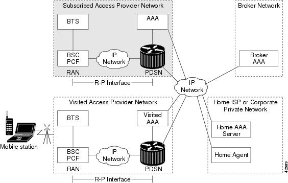
CDMA is one of the standards for mobile communication. A typical CDMA2000 network includes terminal equipment, mobile termination, base transceiver stations (BTSs), base station controllers (BSCs), PDSNs, and other CDMA network and data network entities. The PDSN is the interface between a BSC and a network router.
Figure 1 illustrates the relationship of the components of a typical CDMA2000 network, including a PDSN and a Home Agent. In this illustration, a roaming mobile station user is receiving data services from a visited access provider network, rather than from the mobile station user's subscribed access provider network.
Figure 1 The CDMA Network
As the illustration shows, the mobile station, which must support either Simple IP or Mobile IP, connects to a radio tower and BTS. The BTS connects to a BSC, which contains a component called the Packet Control Function (PCF). The PCF communicates with the Cisco PDSN through an A10/A11 interface. The A10 interface is for user data and the A11 interface is for control messages. This interface is also known as the RAN-to-PDSN (R-P) interface. For the Cisco Home Agent Release 2.0, you must use a Fast Ethernet (FE) interface as the R-P interface on the Cisco 7200 platform, and a Giga Ethernet (GE) interface on the Cisco Multi-Processor WAN Application Module (MWAM) platform.
The IP networking between the PDSN and external data networks is through the PDSN-to-intranet/Internet (Pi) interface. For the Cisco Home Agent, you can use either an FE or GE interface as the Pi interface.
For "back office" connectivity, such as connections to a AAA server, the interface is media independent. Any of the interfaces supported on the Cisco 7206 can be used to connect to these types of services, but we recommends that you use either an FE or GE interface as the Pi interface.
Cisco Home Agent Network
Figure 2 illustrates the functional elements in a typical CDMA2000 packet data system, and Cisco products that are currently available to support this solution. The Home Agent, in conjunction with the PDSN and Foreign Agent, allows a mobile station with Mobile IP client function, to access the Internet or corporate intranet using Mobile IP-based service access. Mobile IP extends user mobility beyond the coverage area of the current, serving PDSN/Foreign Agent. If another PDSN is allocated to the call (following a handoff), the target PDSN performs a Mobile IP registration with the Home Agent; this ensures that the same home address is allocated to the mobile station. Additionally, clients without a Mobile IP client can also make use of these services by using the Proxy Mobile IP capability provided by the PDSN.
The Home Agent, then, is the anchor point for mobile terminals for which MobileIP or Proxy MobileIP services are provided. Traffic is routed through the Home Agent, and the Home Agent also provides Proxy ARP services. In the case of reverse tunneling, traffic from the terminal is also routed through the Home Agent.
Figure 2 Cisco Products for CDMA2000 Packet Data Services Solution
For Mobile IP services, the Home Agent would typically be located within an ISP network, or within a corporate domain. However, many ISPs and/or corporate entities may not be ready to provision Home Agents by the time service providers begin rollout of third-generation packet data services. As a remedy, Access service providers could provision Home Agents within their own domains, and then forward packets to ISPs or corporate domains using VPDN services. Figure 3 illustrates the functional elements that are necessary to support Mobile IP-based service access when the Home Agent is located in the service provider domain.
Figure 3
Cisco Mobile IP-Based Service Access With Home Agent in Service Provider Network
For Mobile IP and Proxy-Mobile IP types of access, these solutions allow a mobile user to roam within and beyond its service provider boundaries, while always being reachable and addressable through the IP address assigned on initial session establishment. Details of Mobile IP and Proxy Mobile IP Services can be found in the Packet Data Services section that follows.
Packet Data Services
In the context of a CDMA2000 network, the Cisco Home Agent supports two types of packet data services: Mobile IP and Proxy Mobile IP services. From the perspective of the Cisco Home Agent, these services are identical.
Cisco Mobile IP Service
With Mobile IP, the mobile station can roam beyond the coverage area of a given PDSN and still maintain the same IP address and application-level connections.
Figure 4 shows the placement of the Cisco Home Agent in a Mobile IP scenario.
Figure 4
CDMA Network—Mobile IP Scenario
The communication process occurs in the following order:
1.
2.
As part of the registration process, the Cisco HA creates a binding table entry to associate the mobile station's home address with its care-of address.
Note
3.
4.
5.
6.
7.
Note
Cisco Proxy Mobile IP Service
For certain service providers there is a lack of commercially available Mobile IP client software, while PPP, which is widely used to connect to an Internet Service Provider (ISP), is ubiquitous in IP devices. As an alternative to Mobile IP, you can use Cisco's Proxy Mobile IP feature. This capability of the Cisco PDSN, which is integrated with PPP, enables the PDSN (functioning as a Foreign Agent) and a Mobile IP client, to provide mobility to authenticated PPP users.
The communication process occurs in the following order:
1.
2.
3.
4.
5.
6.
Note
Features
New Features in Release 2.0
This section describes features that were introduced or modified in Home Agent Release 2.0.
•
•
•
•
•
•
This section describes key features from previous releases of the Cisco Home Agent:
•
Feature Support
In addition to supporting Cisco IOS networking features, a Cisco 7200 series router, Cisco 6500 series switch, or Cisco 7600 series router, configured as a Home Agent, supports the following Home Agent-specific features:
•
–
–
•
–
–
•
•
•
–
–
–
•
–
–
•
•
•
–
–
•
•
•
–
•
–
–
•
•
Benefits
•
•
•
Note
•
•
•
•
•
•
•
•
The Home Agent
The Home Agent (HA) maintains mobile user registrations and tunnels packets destined for the mobile to the PDSN/FA. It supports reverse tunneling, and can securely tunnel packets to the PDSN using IPSec. Broadcast packets are not tunneled. Additionally, the HA performs dynamic home address assignment for the mobile. Home address assignment can be from address pools configured locally, through either DHCP server access, or from the AAA server.
The Cisco HA supports proxy Mobile IP functionality, and is available on the 7600, 7200, and 6500 series platforms. A Cisco HA based on the Cisco 7200 series router supports up to 262,000 mobile bindings, can process 100 bindings per second, and is RFC 2002, RFC 2003, RFC 2005 and RFC2006 compliant.
A Cisco HA based on the Cisco 76 00 series router or Cisco Catalyst 6500 switch, with two MWAM cards housing five active HA images and five standby images, would support the above figures multiplied by 5.
For more information on Mobile IP as it relates to Home Agent configuration tasks, please refer to the following url:
http://www.cisco.com/univercd/cc/td/doc/product/software/ios120/120newft/120t/120t1/mobileip.htm.
Mobile IPv4 Registration Revocation
Basic Mobile IP resource revocation is an IS-835-C initiative that defines the methods by which a mobility agent (one that provides Mobile IP services to a mobile node) can notify the other mobility agent of the termination of a registration due to administrative reasons or MIP handoff.
This feature is similar to the Cisco MobileIP Bind Update feature. When a mobile changes its point of attachment (FA), or needs to terminate the session administratively, the HA sends a registration revocation message to the old FA. The old FA tears down the session and sends registration revocation acknowledgement message to the HA. In another scenario, if the PDSN/FA needs to terminate the session administratively, the FA sends registration revocation message to the HA. The HA deletes the binding for the mobile and sends registration revocation acknowledgement to FA.
An HA configured to support registration revocation in Mobile Ipv4 includes a revocation support extension in all MIP RRP for the associated MIP RRQ from the PDSN that contained a valid registration revocation extension. A registration for which the HA received a revocation support extension, and responded with a subsequent revocation support extension, is considered revocable by the HA.
The following sample call flow illustrates Mobile IP Resource Revocation (Registration phase):
Step 1
Step 2
Step 3
Step 4
Step 5
The following sample call flow illustrates Mobile IP Resource Revocation (HA initiated):
Step 1
Step 2
Step 3
Step 4
Step 5
Step 6
Step 7
Step 8
The following call flow illustrates a Mobile IP Resource Revocation (FA initiated revocation):
Step 1
Step 2
Step 3
Step 4
Step 5
Step 6
I-bit Support
The I (Inform) bit is used during the registration revocation phase to notify the mobile node (MN) of the revoked data service in cases where the mobile node has more than one MobileIP flows. If, during the registration phase, this bit is set to 1 by a mobility agent in the revocation support extension in the RRQ/RRP, it indicates that the agent supports the use of the "I" bit in revocation messages.
In the current implementation, if MobileIP RRQ is received with I bit set in the revocation support extension, then the HA will also set the I-bit to 1, and the I-bit shall be considered to be used during the revocation phase. When the HA initiates revocation, and if the I bit was negotiated, it shall set the I bit to 1 in the Revocation message if a binding is administratively released, and will set it to 0 if a inter- PDSN handoff is detected by the HA. When revocation is initiated by the PDSN, and the revocation message has I-bit set to 1, then the HA will also set the I-bit to 1 in the revocation ACK message.
Mobile IPv4 Resource Revocation Restrictions
The following list identifies the restrictions for Mobile IPv4 Resource Revocation feature for the current release:
•
•
•
•
•
HA Server Load Balancing
The HA-Server Load Balancing (HA-SLB) feature is built upon the existing IOS Server Load Balancing (SLB) feature. SLB allows users to represent a group of network servers (a server farm) as a single server instance, balance the traffic to the servers, and limit traffic to individual servers. The single server instance that represents a server farm is referred to as a virtual server. The servers that comprise the server farm are referred to as real servers.
SLB can distribute the traffic to real servers through mechanisms like round robin to real servers. Additionally, it can monitor the health of each real server using the Dynamic Feedback Protocol, choose a server that has the least load, and choose a server that is up and running. Please refer to the following URL for more information on SLB architecture:
The HA-SLB feature is available on the 6500 and 7600 series platforms. This feature allows a set of real Home Agents, each running on an MWAM, to be identified by a single virtual server IP address residing on 6500 and 7600 Supervisor.
PDSN/FAs send an initial registration request for a user to the virtual server IP address. HA-SLB running on the SUP intercepts the packets and forwards the registration request to one of the real Home Agents.
A typical call flow would have the following sequence of events:
Step 1
Step 2
Step 3
Step 4
Step 5
Note
Step 6
Note
RRQs destined to the HA/SLB virtual IP address, with an HA address of 0.0.0.0 or 255.255.255.255, are forwarded to the actual HA using a weighted "round-robin," load balancing algorithm. The SLB mechanism supports Dynamic Feedback Protocol (DFP) that gives real servers the ability to communicate real server health to the load balancer, thereby adjusting the weight of the reals server in the load balancing algorithms.
Since the MN can send multiple RRQs before it hears a RRP from the HA (either the MN power cycles after sending an initial RRQ, or it is mis-configured to send multiple initial registrations, or RRPs are dropped by the network), it is important to keep track of registrations coming from the same MN. This avoids the case where the same MN is registered at multiple HAs, and wastes IP addresses and other resources at those HAs. To solve this problem, HA-SLB would parse the RRQ and create a session object indexed by the MNs NAI. This session object will store the real HA IP address where the RRQ was forwarded. Subsequent registrations from the same MN will be forwarded to this same real HA. The session object will be stored for a configurable period of time (default to 10 seconds). If the HA-SLB does not see a RRQ from the MN within this period of time, the session object is cleared. If HA-SLB sees a RRQ, the timer associated with the session object is reset.
A retry counter is associated with each session object, and is incremented for each re-transmitted RRQ seen by the load balancer. If the number of retries seen is greater than the configured "reassign" threshold, the session sending the retransmissions will be re-assigned to another real HA, and a connection failure is recorded for the original real HA. Real servers are assumed to be down and no more RRQs re-directed to them when enough connection failures are seen to reach a configured threshold. HA-SLB will restart directing sessions to that real server after a configurable time interval or if the real server sends a DFP message to HA-SLB.
Load Balancing in HA-SLB
HA-SLB uses a weighted round-robin load-balancing algorithm. This algorithm specifies that the real server used for a new connection to the virtual server is chosen from the server farm in a circular fashion. Each real server is assigned a weight n, that represents its capacity to handle connections, as compared to the other real servers associated with the virtual server. As an example, assume a server farm comprised of real server ServerA with n = 3, ServerB with n = 1, and ServerC with n = 2. The first three RRQs to the virtual server are assigned to ServerA, the fourth RRQ to ServerB, and the fifth and sixth RRQs to ServerC.
It is possible to configure IOS SLB for either static or dynamic load balancing. Static load balancing is achieved by assigning weights statically to each HA in the server farm. Dynamic load balancing is achieved by configuring Dynamic Feedback Protocol (DFP), with the DFP manager on SLB, and the DFP client on each of the real HAs.
HA-SLB Operating Modes
HA-SLB operates in two modes, Dispatched mode and Direct (NAT server) mode.
In Dispatched mode the virtual server address is known to the HAs. HA-SLB will simply redirect packets to the HAs at the MAC layer. This requires the HAs to be layer 2 adjacent to SLB.
In Direct mode, HA-SLB works in NAT server mode and routes the RRQs to the HAs by changing the destination IP address in the RRQ to that of the real server. As a result the HAs need not be layer 2 adjacent to SLB.
HA Accounting
This feature is primarily developed to allow the HA to interoperate with the Service Selection Gateway (SSG) in the CMX solution. However, this feature can also be used without SSG interaction. The HA Accounting feature includes the following activities:
•
•
•
The following attributes will be sent in Accounting Records:
–
–
–
–
–
–
–
–
Basic Accounting Messages
Home Agent Release 2.0 supports the Cisco Service Selection Gateway (SSG). In this release, the HA sends only three accounting messages without statistics information. The SSG is designed and deployed in such a way that all the network traffic passes through it.
Since all the traffic passes through the SSG, it has all of the statistical information; however, it does not have Mobile IP session information. The Home Agent has the Mobile IP session information, and sends that information to the SSG.
The HA sends the following messages to the SSG/AAA server:
•
–
–
•
•
–
–
–
All the messages contain the following information:
•
•
•
•
Messages Not Sent By Mobile IP Home Agent
The following messages are not sent by Mobile IP Home Agent.
•
•
HA Accounting Restrictions
The following list identifies the restrictions for the HA Accounting feature for the current release:
•
Skip HA-CHAP with MN-FA Challenge Extension (MFCE)
This feature allows the HA to download a Security Association (SA) and cache it locally on the disk, rather than performing a HA-CHAP procedure with Home AAA server to download the SA for the user for each registration request. When a user first registers with the HA, the HA does HA-CHAP (MN-AAA authentication), downloads the SA, and caches it locally. On subsequent re-registration requests, the HA uses the locally cached SA to authenticate the user. The SA cache entry is removed when the binding for the user is deleted.
VRF Support on HA
The HA supports overlapping IP address for mobile nodes for the mobile IP flows that are opened for different realms. This feature is based on the Multi-VPN Routing and Forwarding (VRF) CE network architecture, and expands the BGP/MPLS VPN architecture to support multiple VPNs (and therefore multiple customers) per Customer Edge (CE) device. This reduces the amount of equipment required, and simplifies administration, while allowing the use of overlapping IP address spaces within the CE network.
Multi-VRF CE is a new feature, introduced in Cisco IOS release 12.2(4)T, that addresses these issues. Multi-VRF CE, also known as VRF-Lite, extends limited PE functionality to a Customer Edge (CE) router in an MPLS-VPN model. A CE router now has the ability to maintain separate VRF tables in order to extend the privacy and security of an MPLS-VPN down to a branch office rather than just at the PE router node. The CE can support traffic separation between customer networks, or between entities within a single customer network. Each VRF on the CE router is mapped to a corresponding VRF on the PE router.
Figure 5
VRF-Lite in the Cisco PDSN/Home Agent Architecture
Figure 5 illustrates the PDSN architecture and how the VRF-lite solution is applied to the Home Agent for different realms/enterprises, thus segregating data between the enterprises.
Highlights of the VRF solution include the following:
•
•
•
•
•
The realm is used to identify an enterprise network. One virtual Home Agent is configured per realm. NAI is part of Mobile IP RRQ, and is the main identifier of mobile IP users in the PDSN and HA. The realm part of NAI will be used to identify the virtual Home Agent. Mobile nodes follow the NAI convention of username@company, where company identifies a realm name that indicates a subscriber community.
Multiple IP addresses are used at the HA to indicate different enterprise conections or VRFs to the PDSN. Thus, there will be one mobile IP tunnel between the PDSN and the HA per realm/VRF.
For an HA that is connected to two enterprises, "abc.com" and "xyz.com," the HA will be configured with two unique IP addresses (typically configured under a loopback interface). The PDSN will have a MoIP tunnel to an address LA1 to reach "abc.com," and will have another MoIP tunnel to address LA2 to reach "xyz.com," where LA1 and LA2 are IP addresses configured under a Loopback interface.
On the home AAA RADIUS server, NAI/domain configuration ensures that the PDSN receives LA1 as the IP address of the Home Agent of enterprise "xyz.com" as part of the Access Response during FA-CHAP or HA-CHAP (MN-AAA authentication); and LA2 as the IP address of Home Agent of enterprise "mnp.com".
This feature will work with HA-SLB solution for HA load balancing.
Mobile IP Tunnel Establishment
The following procedure describes a mobile IP flow establishment with HA-SLB and VRF enabled. Elements in this call flow are two Mobile nodes (MN-1 and MN-2) belonging to enterprise ENT-1 & ENT-2 respectively:
Step 1
Step 2
Step 3
Step 4
Step 5
Step 6
Step 7
Step 8
Step 9
Step 10
Step 11
VRF Feature Restrictions
The following list identifies restrictions for the VRF feature:
•
•
•
Authentication and Accounting Server Groups Per Realm
Separate authentication and accounting groups can be specified across different realms. Based on the realm of the user, the HA will choose the AAA authentication server based on the authentication group specified for the realm on the HA. Similarly, the HA will choose a AAA accounting server based on the realm of the user if the accounting group is specified for the realm.
Note
Hot-lining
HA Release 2.0 supports hot-lining for mobile nodes based on the Nortel X31-20031013-0xx (October 2003). The hot-lining feature enables you to monitor upstream user traffic using two different scenarios—active and new session. When hot-lining is active for a particular user, the upstream IP packets from the mobile are re-directed to the Re-direct server that is configured for this particular realm. Re-direction is achieved by changing the IP packet destination address to the Re-direct server address. The only mandatory attribute supported in the Change of Authorization (CoA) message from the HAAA is the User-Name attribute to identify the particular user on the Home Agent. Optionally, IP address can also be sent in the CoA message to identify the particular binding for a particular user.
Active Session Hot-Lining
For active session Hot-lining, the user starts a packet data session. In the middle of the session it is hot-lined and after the account is reconciled, the hot-lining on the session is removed. Hot-lining is done with a RADIUS Change of Authorization (CoA) message. The following procedure lists the events for active session Hot-lining:
Step 1
Step 2
Step 3
Step 4
Step 5
Step 6
Step 7
Step 8
Step 9
Step 10
Step 11
Step 12
Step 13
Step 14
Step 15
Step 16
New Session Hot-Lining
For New Session Hot-lining, the user's session is hot-lined at the time of packet data session establishment. In this scenario the RADIUS Access-Accept message is used to hot-line the session. The following procedure lists the events for New Session Hot-lining:
Step 1
Step 2
Step 3
Step 4
Step 5
Step 6
Step 7
Restrictions for Hot-lining
The following list includes restrictions for the Hot-Lining feature:
•
•
•
•
•
•
•
Radius Disconnect
Radius Disconnect (or Packet of Disconnect (PoD)) is a mechanism where in the RADIUS server can send a Radius Disconnect Message to the HA to release resources. Resources may be released for administrative purposes. Resources are mainly Mobile IP bindings on the HA.
Support for Radius Disconnect on the Cisco Home Agent is in conformance with RFC 3576. The HA communicates its resource management capabilities to the Home AAA server in an Access Request message sent for authentication/authorization procedure by including a 3GPP2 Vendor Specific Session Termination Capability (STC) VSA. The value communicated in the STC VSA will be obtained from configuration. The HA will also include NAS-Identifier attribute containing its Fully Qualified Domain Name (FQDN) in the Access Request when the radius-server attribute 32 include-in-access-req format CLI is configured.
The following approach is followed when a Disconnect Request is received on the HA:
Step 1
Step 2
Step 3
Restrictions for RADIUS Disconnect
The following list includes restrictions for the RADIUS Disconnect feature:
•
•
Conditional Debugging
The HA supports conditional debugging based on NAI, as well as conditional debugging based on the MN's Home address. Only AAA and Mobile IP components will support conditional debugging.
To enable conditional debugging based on NAI, you must execute the debug condition username nai command.
To enable conditional debugging based on the MN's home address, you must execute the debug condition ip mn-ip-addr.
The following MobileIP debugs are supported for conditional debugging :
•
•
•
The following AAA debugs are supported for conditional debugging :
•
•
•
•
•
•
•
The following RADIUS debugs are supported for conditional debugging :
•
•
•
•
•
•
Dynamic Home Agent Assignment
The Home Agent can be dynamically assigned in a CDMA2000 network when the following qualifications exist.
The first qualification is that the Home Agent receives a Mobile IP registration request with a value of 0.0.0.0 in the Home Agent field. Upon authentication/authorization, the PDSN retrieves the HA's IP address. The PDSN then uses this address to forward the Registration Request to the HA, but does not update the actual HA address field in the Registration Request.
The Home Agent sends a Registration Reply, and places it's own IP address in the Home Agent field. At this point, any re-registration requests that are received would contain the Home Agent's IP address in the Home Agent field.
The second qualification is a function of the PDSN/Foreign Agent, and is included here for completeness. In this case, a AAA server is used to perform the dynamic Home Agent assignment function. Depending on network topology, either the local-AAA, or the home-AAA server would perform this function. When an access service provider is also serving as an ISP, Home Agents would be located in the access provider network. In this service scenario, a local-AAA server would perform Home Agent assignment function. Based on the user NAI received in the access request message, the AAA server would return a elected Home Agent's address in an access reply message to the PDSN.
A pool of Home Agent addresses is typically configured at the AAA server. For the access provider serving as an ISP, multiple pools of Home Agents could be configured at the local AAA server; however, this depends on SLAs with the domains for which Mobile IP, or proxy-Mobile IP services are supported. You can configure the Home Agent selection procedure at the AAA server, using either a round-robin or a hashing algorithm over user NAI selection criteria.
The PDSN/Foreign Agent sends the Registration Request to the Home Agent; however, there is no IP address in the HA field of the MIP RRQ (it is 0.0.0.0). When the PDSN retrieves the IP address from AAA, it does not update the MIP RRQ; instead, it forwards the RRQ to the HA address retrieved. The PDSN cannot alter the MIP RRQ because it does not know the MN-HA SPI, and key value (which contains the IP address of the Home Agent in the "Home Agent" field). Depending on network topology, either the local AAA, or the home AAA server would perform this function. In situations where the Home Agents are located in the access provider network, the local AAA server would perform Home Agent assignment function. Additionally, multiple pools of Home Agents could be configured at the local AAA server, depending on SLAs with the domains for which Mobile IP, or proxy Mobile IP services are supported.
Home Agent Redundancy
Cisco Home Agents can be configured to provide 1:1 redundancy. Two Home Agents are configured in hot-standby mode, based on Cisco Hot Standby Routing Protocol (HSRP in RFC 2281). This enables the active Home Agent to continually copy mobile session-related information to the standby Home Agent, and maintains synchronized state information at both Home Agents. In case an active Home Agent fails, the standby Home Agent takes over without service disruption.
Note
The Home Agent Redundancy feature is supported for Static IP Address assignment and IP Address assignment by AAA. Starting in Release 2.0, the Home Agent Redundancy feature is supported for Dynamic IP Address assignment using local IP address pools and Dynamic IP Address assignment using Proxy DHCP.
When Home Agent Redundancy is configured with Dynamic IP Address assignment using Proxy DHCP, the DHCP information is not synced with the standby while the bindings are brought up, even though the bindings are synced to the standby HA. However, when the standby HA becomes active, a DHCP request for each existing binding is sent out to the DHCP server in order to update the DHCP related information on this Home Agent.
The following features are not supported with HA redundancy:
•
•
•
During the Mobile IP registration process, an HA creates a mobility binding table that maps the home IP address of an MN to the current care-of address of the MN. If the HA fails, the mobility binding table is lost and all MNs registered with the HA lose connectivity. To reduce the impact of an HA failure, Cisco IOS software supports the HA redundancy feature.
Note
The functionality of HA Redundancy runs on top of the Hot Standby Router Protocol (HSRP). HSRP is a protocol developed by Cisco that provides network redundancy in a way that ensures that user traffic immediately and transparently recovers from failures.
HSRP Groups
Before configuring HA Redundancy, you must understand the concept of HSRP groups.
An HSRP group is composed of two or more routers that share an IP address and a MAC (Layer 2) address and act as a single virtual router. For example, your Mobile IP topology can include one active HA and one or more standby HAs that the rest of the topology view as a single virtual HA.
You must define certain HSRP group attributes on the interfaces of the HAs so that Mobile IP can implement the redundancy. You can use the groups to provide redundancy for MNs with a home link on either the interface of the group (a physical network) or on virtual networks. Virtual networks are logical circuits that are programmed and share a common physical infrastructure.
How HA Redundancy Works
The HA Redundancy feature enables you to configure an active HA and one or more standby HAs. The HAs in a redundancy group may be configured in an active HA-standby HA role if the HAs are supporting physical networks, or in a Peer HA-Peer HA role if they are supporting virtual networks.
In the first case, the active HA assumes the lead HA role, and synchronizes the standby HA. In the case of virtual network support, Peer HAs share the lead HA role and "update" each other. The Peer HA configuration allows for load balancing of the incoming RRQs, as either HA may receive RRQs. In either scenario, the HAs participating in the redundancy group should be configured similarly. The current support structure is 1 to1 to provide the maximum robustness and transparency in failover.
HA functionality is a service provided by the router and is not interface specific. Therefore, the HA and the MN must agree on which HA interface the MN should send its registration requests and, conversely, on which HA interface the HA should receive the registration requests. This agreement must factor in the following two scenarios:
•
•
For MNs on physical networks, an active HA accepts registration requests from the MN and sends binding updates to the standby HA. This process keeps the mobility binding tables on the active and standby HAs synchronized.
For MNs on virtual networks, the active and standby HAs are peers—either HA can handle registration requests from the MN and update the mobility binding table on the peer HA.
When a standby HA comes up, it must request all mobility binding information from the active HA. The active HA responds by downloading the mobility binding table to the standby HA. The standby HA acknowledges that it has received the requested binding information. Figure 6 illustrates an active HA downloading the mobility bindings to a standby HA. A main concern in this stage of the process is which HA IP interface the standby HA should use to retrieve the appropriate mobility binding table, and on which interface of the standby HA the binding request should be sent.
Figure 6
Overview of HA Redundancy and Mobility Binding Process
Note
Support for Binding Deletion Synch
In the current implementation of Home Agent redundancy, bindings that are deleted on the active HA in active-standby mode (or on any peer in a peer to peer mode), due to receipt of a revocation message, a RADIUS disconnect message, or an administrative clear, are not synched to the standby HA or the peer HA. Also, the additional extensions and attributes for Revocation and Radius Disconnect are not relayed to the standby. In Cisco IOS release 12.3(7) XJ1, Registration Revocation, Radius Disconnect and Administrative clear using the clear ip mobile binding command are supported with HA redundancy. The following list identifies the benefits of this support:
Active-Standby Mode of HA Redundancy:
•
•
•
•
Peer-to-Peer Mode of HA Redundancy:
•
•
•
As part of this support, two new messages —"Bind Delete Request" and "Bind Delete Ack"—are introduced that are exchanged between the redundant HAs when a binding is deleted. The following call flow illustrates when a binding gets deleted on the active Home Agent due to receipt of Revocation message, and the deletion of binding is synched to the standby Home Agent.
1.
2.
3.
4.
5.
6.
During binding synch, the extensions (Revocation Support Extension) and attributes for Revocation and Radius Disconnect (STC attribute) are synched from active HA to the standby. In scenarios when the active HA goes down and the standby becomes active, the now active HA is capable of deleting bindings on receipt of a RADIUS Disconnect message. For revocation, the bindings on the now active HA are revocable, and the HA is capable of receiving and sending revocation messages.
Physical Network Support
For MNs on physical networks, the HAs are configured in the active HA-standby HA configurations as shown in Figure 7 and Figure 8. The MNs that are supported on this physical network are configured with the HSRP virtual group address as the HA address. Hence, only the activeactive HA can accept RRQs from the MN because it is the owner of the HSRP virtual group address. Upon receipt of an authenticated RRQ, the active HA sends a binding update to the standby HA.
HA Redundancy for physical networks can support multiple HAs in the redundancy group, although only one HA can be in active state, and only one HA can be in standby state. For example, consider the scenario in which there are four HAs in the redundancy group (that is, one active HA, one standby HA, and two HAs in listen state). If the active HA fails, the standby HA becomes the active HA, and the HA in listen state with higher priority becomes the standby HA.
Figure 7
Virtual Network Support Using One Physical Network (Peer HA-Peer HA)
Figure 8
Virtual Network Support Using Multiple Physical Networks (Peer HA-Peer HA)
Virtual Networks
Mobile IP calls for each MN are associated with the home network from which the MN's home IP address is allocated. It is often assumed that this should be a physical network, but there are many cases in deployment where it does not make sense to have each MN attached to a physical network. IOS Mobile IP supports the creation of a software interface called a virtual network. A virtual network is very similar to a loopback interface, but it is owned by the Mobile IP process. Using virtual networks saves Interface Descriptor Blocks (IDBs), and allows Mobile IP specific control over how packets are dropped. When using virtual networks the mobile node is always considered roaming, it can never be attached to its home network. In real world deployments, this can cause some semantic problems. For example in cellular deployment a user may be in their home calling area, but will be roaming from a Mobile IP perspective.
Virtual networks are configured and referenced by a network number and mask pair. It is also possible to associate the virtual network with a Home Agent address for redundancy purposes. Here is an example:
ip mobile virtual-network 10.0.0.0 255.255.2550.0 address 192.168.100.1ip mobile host 10.0.0.1 10.0.0.254 virtual-network 10.0.0.0 255.255.255.0Virtual network routes are owned by the Mobile IP routing process and therefore must be redistributed into other routing protocols in order to be propagated. Here is an example:
router ripredistribute mobileSupport for Discontinuous IP Address Pools for the Same Realm
This feature allows the user to specify discontinuous IP address pools for the same realm so that mobiles with NAI can have home addresses assigned from a pool of discontiguous IP address ranges. This will allow the Home Agent to accept Mobiles belonging to multiple virtual networks for the same host group.
This is achieved by configuring a local pool on HA covering the IP address ranges for multiple virtual-networks, and specifying one of the virtual-networks as the home network for the given realm.
The following configuration can be used to allow the HA to accept MNs belonging to multiple virtual networks for the same host group.
ip local pool pool1 1.1.1.1 1.1.1.250ip local pool pool1 1.1.2.1 1.1.2.250ip mobile home-agentip mobile virtual-network 1.1.1.0 255.255.255.0ip mobile virtual-network 1.1.2.0 255.255.255.0ip mobile host nai @xyz.com address pool local pool1 virtual-network 1.1.1.0 255.255.255.0 aaa lifetime 65535In the above configuration, two virtual networks are configured and the local pool (pool1) is configured to include the IP addresses for both the virtual networks. By specifying one of the virtual networks and the local pool name in the ip mobile host command, the HA will accept MNs belonging to both the networks for the same realm.
Home Address Assignment
The Home Agent assigns a home address to the mobile node based on user NAI received during Mobile IP registration. The IP addresses assigned to a mobile station may be statically or dynamically assigned. The Home Agent does not permit simultaneous registrations for different NAIs with the same IP address, whether it is statically or dynamically assigned.
Static IP Address
A static IP address is an address that is pre-assigned to the mobile station, and possibly preconfigured at the mobile device. The Home Agent supports static addresses that might be public IP addresses, or addresses in private domain.
Note
The mobile user proposes the configured or available address as a non-zero home address in the registration request message. The Home Agent may accept this address or return another address in the registration reply message. The Home Agent may obtain the IP address by accessing the home AAA server or DHCP server. The home AAA server may return the name of a local pool, or a single IP address. On successful Mobile IP registration, Mobile IP based services are made available to the user.
Static Home Addressing Without NAI
The original Mobile IP specification supported only static addressing of mobile nodes. The home IP address served as the "user name" portion of the authentication. Static addressing can be beneficial because it allows each device to keep the same address all the time no matter where it is attached to the network. This allows the user to run mobile terminated services without updating the DNS, or some other form of address resolution. It is also easy to manage MNs with static addressing because the home address and the Home Agent are always the same. However, provisioning and maintenance are much more difficult with static addressing because address allocation must be handled manually, and both the Home Agent and MN must be updated. Here is an example configuration:
router (config)# ip mobile host 10.0.0.5 interface FastEthernet0/0router (config)# ip mobile host 10.0.0.10 10.0.0.15 interface FastEthernet0/0router (config)# ip mobile secure host 10.0.0.12 spi 100 key ascii secretStatic Home Addressing with NAI
Static home addressing can also be used in conjunction with NAI to support a NAI based authorization and other services. It is also possible to allow a single user to use multiple static IP addresses either on the same device, or multiple devices, while maintaining only one AAA record and security association. A user must be authorized to use an address before the registration will be accepted. Addresses can be authorized either locally, or through a AAA server. If a MN requests an address which is already associated with a binding that has a different NAI, the HA will attempt to return another address from the pool unless the command is set.
Here is a sample configuration:
router (config)# ip mobile home-agent reject-static-addrLocal Authorization
A static address can be authorized on a per MN or per realm basis using configuration commands. Per MN configurations require that you define a specific NAI in the user or user@realm form. Per realm configurations require that you define a generic NAI in the @realm form, and allow only the specification of a local pool.
Here is a sample configuration:
router (config)# ip local pool static-pool 10.0.0.5 10.0.0.10router (config)# ip mobile host nai user@staticuser.com static-address 10.0.0.1 10.0.0.2interface FastEthernet0/0router (config)# ip mobile host nai user@staticuser.com static-address local-pool static-pool interface FastEthernet0/0router (config)# ip mobile host nai @static.com static-address local-pool static-poolinterface FastEthernet0/0AAA Authorization
It is also possible to store either the authorized addresses, or local pool name in a AAA server. Each user must have either the static-ip-addresses attribute or the static-ip-pool attribute configured in the AAA server. Unlike the static address configuration on the command line, the static-ip-addresses attribute is not limited in the number of addresses that can be returned.
Here is a sample configuration.
HA configuration:
router (config)# ip local pool static-pool 10.0.0.5 10.0.0.10router (config)# ip mobile host nai user@staticuser.com interface FastEthernet0/0 aaarouter (config)# ip mobile host nai @static.com interface FastEthernet0/0 aaaRadius Attributes:
Cisco-AVPair = "mobileip:static-ip-addresses=10.0.0.1 10.0.0.2 10.0.0.3"
Cisco-AVPair = "mobileip:static-ip-pool=static-pool"
Dynamic IP Address
It is not necessary for a home IP address to be configured in the mobile station to access packet data services. A mobile user may request a dynamically assigned address by proposing an all-zero home address in the registration request message. The Home Agent assigns a home address and returns it to the MN in the registration reply message. The Home Agent obtains the IP address by accessing the home AAA server. The AAA server returns the name of a local pool or a single IP address. On successful registration, Mobile IP based services are made available to the user.
Fixed Addressing
It is possible to configure the Home Agent with a fixed address for each NAI. The fixed address is assigned to the MN each time it registers. This provides users all the benefits of static addressing while simplifying the configuration of the MN. We do not recommend fixed addressing for large-scale deployment because the Home Agent configuration must be updated to perform user all maintenance.
Here is a sample configuration:
router# ip mobile host nai user@realm.com address 10.0.0.1 interface FastEthernet0/0Local Pool Assignment
Local pool assignment requires that one or more address pools be configured on the HA. The HA allocates addresses from the pool on a first come, first served basis. The MN will keep the address as long as it has an active binding in the HA. The MN may update it's binding by sending a RRQ with either the allocated address, or 0.0.0.0 as it's home address. When the binding expires the address is immediately returned to the pool.
Note
Here is a sample configuration:
router (config)# ip local pool mippool 10.0.0.5 10.0.0.250router (config)# ip mobile host nai @localpool.com address pool local mippool virtual-network 10.0.0.0 255.255.255.0DHCP Allocation
The Dynamic Host Configuration Protocol (DHCP) is already a widely used method of allocating IP addresses for desktop computers. IOS Mobile IP leverages the existing DHCP proxy client in IOS to allow the home address to be allocated by a DHCP server. The NAI is sent in the Client-ID option and can be used to provide dynamic DNS services.
Here is a sample configuration:
router (config)# ip mobile host nai @dhcppool.com address pool dhcp-proxy-client
dhcp-server 10.1.2.3 interface FastEthernet 0/0
Note
Dynamic Addressing from AAA
Dynamic addressing from AAA allows the operator to support fixed and/or per session addressing for MNs without the trouble of maintaining addressing at the MN or HA. The AAA server can return either a specific address, a local pool name, or a DHCP server address. If the AAA server is being used to return a specific address the home address can either be configured as an attribute on the NAI entry in the RADIUS database, or can be allocated from a pool depending on the capabilities of the AAA server being used. The AAA server can also return the name of a local pool configured on the HA or a DHCP server IP address.
Her e is a sample configuration.
On the HA:
router (config)# ip local pool dynamic-pool 10.0.0.5 10.0.0.10router (config)# ip mobile host nai user@staticuser.com interface FastEthernet0/0 aaarouter (config)# ip mobile host nai @static.com interface FastEthernet0/0 aaaAAA Address assignment:
Cisco-AVPair = "mobileip:ip-address=65.0.0.71"AAA Local Pool attribute:
Cisco-AVPair = "mobileip:ip-pool=dynamic-pool"AAA DHCP server attribute:
Cisco-AVPair = "mobileip:dhcp-server=10.1.5.10"On-Demand Address Pool (ODAP)
If you use MWAM cards to provide a higher density of HAs, you may choose to have IP addresses allocated from a central source. Cisco's IOS On-Demand Address Pools (ODAPs) provides this functionality. ODAP simplifies HA configuration, in that you will not have to configure a local pool of IP addresses in each HA configuration.
You can use ODAP to centralize the management of large pools of addresses and simplify the configuration of large networks. The ODAP feature consists of two components:
•
•
A DHCP ODAP subnet allocation server is configured to create and allocate pools of IP address space on a per-subnet basis. The size of these pools is configurable, and these subnets will be leased to the ODAP managers on the HA, and they provide subnet allocation pools for the ODAP manager allocation. The DHCP ODAP subnet allocation server functionality can reside on one of the HA instances on the MWAM. The DHCP ODAP subnet allocation server functionality can also reside on another external Cisco IOS router, or an external Cisco Access Register.
The ODAP manager functionality resides on each HA image. Rather than using local IP pools, the HA uses the ODAP manager functionality. The ODAP manager leases subnets from the ODAP subnet allocation server based on the demand for IP addresses and subnet availability to each HA. The ODAP manager on the HA assigns addresses to clients from these subnets, and dynamically increases or decreases the subnet pool size depending on address utilization. When an HA ODAP manager leases a subnet, a summarized route is automatically added for each subnet that the HA receives. This route is added to the Null interface and is a static route.
When the ODAP manager on the HA allocates a subnet, the ODAP subnet allocation server creates a subnet binding. This binding is stored in the DHCP database for as long as the ODAP manager needs the address space. The binding is destroyed and the subnet returned to the subnet pool only when the HA ODAP manager releases the subnet as the address space utilization decreases.
The DHCP ODAP subnet allocation server has enhanced DHCP functionality. Instead of returning a single IP address, it returns a subnet of addresses. The ODAP manager manages this pool of IP addresses on the HA. This functionality provides a more efficient route summarization for the routing protocols.
ODAP Restrictions
The following list identifies restrictions for the ODAP feature:
•
•
•
Address Assignment for Same NAI - Multiple Static Addresses
The Cisco Home Agent supports multiple Mobile IP registrations for the same NAI with different static addresses. This is accomplished by configuring static-ip-address pool(s) at the home-AAA or DHCP server. When the HA receives a Registration Request message from the mobile user, the HA accesses the home-AAA for authentication, and possibly for assignment of an IP address. The NAI provided by the mobile user is sent to the home-AAA. The home-AAA server returns a list of static-IP-addresses or the static-ip-pool name corresponding to this NAI.
Address Assignment For Same NAI - Different Mobile Terminal
When the same NAI is used for registration from two different mobiles, the behavior is as follows:
•
•
•
•
3 DES Encryption
The Cisco Home Agent includes 3DES encryption, which supports IPSec on the HA. To accomplish this on the 7200 router platform, Cisco supplies an SA-ISA card for hardware provided IPsec. On the 7600 and 6500 platforms, the MWAM utilizes the Cisco IPSec Acceleration Card.
The HA requires you to configure the parameters for each PDSN before a mobile ip data traffic tunnel is established between the PDSN and the HA.
Note
Mobile IP IPSec
The Internet Engineering Task Force (IETF) has developed a framework of open standards called IP Security (IPSec) that provides data confidentiality, data integrity, and data authentication between participating peers. IPSec provides these security services at the IP layer; it uses Internet Key Exchange (IKE) to handle negotiation of protocols and algorithms based on local policy, and to generate the encryption and authentication keys to be used by IPSec. IPSec can be used to protect one or more data flows between a pair of hosts, between a pair of security gateways, or between a security gateway and a host.
The HA uses any statically configured shared secret(s) when processing authentication extension(s) present in mobile IP registration messages.
The HA supports IPSec, IKE, Authentication Header (AH) and IP Encapsulating Security Payload (ESP) as required in IS-835-B.
IS835-B specifies three mechanisms for providing IPSec security:
•
•
•
Note
As per IS-835-B, The HA and AAA should be configured with same security level for a PDSN. The PDSN receives a security level from AAA server and initiates IKE, and the HA responds to IKE request for establishing security policy.
The PDSN receives a security level from the AAA server and initiates IKE, and the HA responds to IKE request for establishing a security policy. All traffic specified by the access-list of the crypto configuration will be protected by IPSec tunnel. The access-list will be configured to protect all traffic between the PDSN and HA, and all bindings belonging to a given PDSN-HA pair will be protected.
IPSec is not applicable to mobiles using Co-located COA
IPSec-based security may be applied on tunnels between the PDSN and the HA depending on parameters received from Home AAA server. A single tunnel may be established between each PDSN-HA pair. It is possible for a single tunnel between the PDSN-HA pair to have three types of traffic streams: Control Messages, Data with IP-in-IP encapsulation, and Data with GRE-in-IP encapsulation. All traffic carried in the tunnel will have same level of protection provided by IPSec.
IS835 defines MobileIP service as described in RFC 2002; the Cisco HA provides Mobile IP service and Proxy Mobile IP service.
In Proxy Mobile service, the Mobile-Node is connected to the PDSN/FA through Simple IP, and the PDSN/FA acts as Mobile IP Proxy for the MN to the HA.
Once Security Associations (SAs or tunnels) are established, they remain active until there is traffic on the tunnel, or the lifetime of the SAs expire.
Note
Figure 9 illustrates the IS835 IPSec network topology.
Figure 9 IS835 IPSec Network
IPSec Interoperability Between the PDSN and HA (IS-835-C)
IPSec rules under IS-835C mandates that connections are always initiated from the PDSN to the Home Agent IP address. Certain PDSNs may not be flexible in their approach to IPSec configuration. These PDSNs do not allow any configuration for Remote IPSec termination points, and hence expect that the remote IPSec termination point is always the Home Agent IP address.
The following section illustrates how to handle IPSec Interoperability between such PDSNs and the HA with Home Agent Release 2.0
The change in the configuration allows for IPSec connections for the Home Agent IP address but still terminated by the VPNSM.
Handling Single Home Agent Instance
This solution is achieved by letting SUP IOS own the same Home Agent IP address. Traffic to the Home Agent is then policy routed to the correct Home Agent.
Figure 10 illustrates a possible configuration:
Figure 10
Single HA Interoperability
Here is a sample configuration for the Supervisor. The PDSN IP Address is 14.0.0.1, HA3 address is 13.0.0.50, and HA4 is 13.0.0.51
Single HA Instance - Interoperability
crypto isakmp policy 1hash md5authentication pre-sharelifetime 60000crypto isakmp key cisco address 0.0.0.0 0.0.0.0!crypto ipsec transform-set mobile-set1 esp-3des# Comment: testmap is used for HA3crypto map testmap local-address Loopback21crypto map testmap 20 ipsec-isakmpset peer 14.0.0.1set transform-set mobile-set1match address 131!interface Loopback21description corresponds to ha-on-proc3ip address 13.0.0.50 255.255.255.255!interface GigabitEthernet4/1description encrypt traffic from vlan 151 to vlan 201& 136 to 139no ip addressflowcontrol receive onflowcontrol send offswitchportswitchport trunk encapsulation dot1qswitchport trunk allowed vlan 1,136,146,151,1002-1005switchport mode trunkcdp enable!interface GigabitEthernet4/2description decrypts traffic from vlan 201 to 151, 139 to 136no ip addressflowcontrol receive onflowcontrol send offswitchportswitchport trunk encapsulation dot1qswitchport trunk allowed vlan 1,139,149,201,1002-1005switchport mode trunkcdp enableinterface Vlan136description secure vlanip address 15.0.0.1 255.255.255.0no ip redirectsno ip unreachablesip policy route-map RRQ-HA3no mop enabledcrypto map testmap!interface Vlan137description internal vlan to HA3ip address 7.0.0.1 255.255.0.0!interface Vlan139no ip addresscrypto connect vlan 136!access-list 131 permit ip host 14.0.0.1 host 13.0.0.50access-list 131 permit ip host 13.0.0.50 host 14.0.0.1access-list 131 permit ip 14.0.0.0 0.0.0.255 13.0.0.0 0.0.0.255access-list 2000 permit udp any any eq mobile-ipaccess-list 2000 permit ipinip any anyroute-map RRQ-HA3 permit 10match ip address 2000set ip next-hop 7.0.0.2!Support for ACLs on Tunnel Interface
The Cisco Tunnel Templates feature allows the configuration of ACLs on statically created tunnels to be applied to dynamic tunnels brought up on the Home Agent. A tunnel template is defined and applied to the tunnels between the Home Agent and PDSN/Foreign Agent.
Here is a sample configuration used to block certain traffic using template tunnel feature:
1.
interface tunnel 10ip access-group 150 in -------> apply access-list 1502.
access-list 150 deny any 10.10.0.0 0.255.255.255access-list permit any any------> permit all but traffic to 10.10.0.0 network3.
ip mobile home-agent template tunnel 10 address 10.0.0.1Support for AAA Attributes MN-HA-SPI and MN-HA SHARED KEY
The Cisco Home Agent supports the following 3GPP2 standard attributes:
MN-HA-SPI (26/57)
MN-HA-SHARED-KEY (26/58)
The following procedure illustrates this support:
1.
2.
3.
4.
5.
User Profiles
The Home Agent maintains a per NAI profile that contains the following parameters:
•
•
•
•
•
•
The profile, identified by the NAI, can be configured locally or retrieved from a AAA server.
Additionally, the Home Agent supports an intelligent security association caching mechanism that optimizes the session establishment rate and mimimizes the time for session establishment.
The Home Agent supports the local configuration of a maximum of 200000 user profiles; on the MWAM, the HA supports 5 x 200000 user profiles. The User profile, identified by the NAI, can be configured locally, or retrieved from a AAA server.
Mobility Binding Association
The mobility binding is identified in the Home Agent in the following ways:
•
•
•
The binding association contains the following information:
•
•
•
•
User Authentication and Authorization
The Home Agent can be configured to authenticate a user using either PAP or CHAP. The Foreign Agent Challenge procedures are supported (RFC 3012) and includes the following extensions:
•
•
•
Note
When configured to authenticate a user with the Home AAA-server, if the Home Agent receives the MN-AAA Authentication Extension in the Registration Request, the contents are used. If the extension is absent, a default configurable password is used.
The Home Agent accepts and maintains the MN-FA challenge extension, and MN-AAA authentication extension (if present), from the original registration for use in later registration updates.
If the Home Agent does not receive a response from the AAA server within a configurable timeout, the message can be retransmitted a configurable number of times. The Home Agent can be configured to communicate with a group of AAA servers, the server being chosen in round-robin fashion from the available configured servers.
Note
HA Binding Update
When a mobile first registers for packet data services, a PPP session and associated Mobile IP flow(s) are established at the PDSN. In the event of an inter-PDSN handoff, another PPP session is established at the target PDSN, and the mobile registers with the Home Agent using the new PDSN/FA. If PPP idle-timeout is configured on the PDSN virtual-template, the maximum mobile IP lifetime advertised to the mobile will be 1 second less than the idle-timeout.
Idle, or unused PPP sessions at a PDSN/Foreign Agent consume valuable resources. The Cisco PDSN/Foreign Agent and Home Agent support Binding Update and Binding Acknowledge messages to release such idle PPP sessions as soon as possible. In the event of an inter-PDSN handoff and Mobile IP registration, the Home Agent updates mobility binding information for the mobile with the Care-of-Address (CoA) of the new PDSN/FA.
If simultaneous bindings are not enabled, the Home Agent sends a notification in the form of a Binding Update message to the previous PDSN/FA. The previous PDSN/FA acknowledges with a Binding Acknowledge, if required, and deletes the visitor list entry for the Mobile IP session. The previous PDSN/FA initiates the release of the PPP session when there are no active flows for that mobile station.
Note
Note
Packet Filtering
The Home Agent can filter both egress packets from an external data network and ingress data packets based on the Foreign Agent IP address or the Mobile Node IP address.
Security
The HA uses any present statically configured shared secret(s) when processing authentication extension(s) present in mobile IP registration messages.
Restrictions
Simultaneous Bindings
The Cisco Home Agent does not support simultaneous bindings. When multiple flows are established for the same NAI, a different IP address is assigned to each flow. This means that simultaneous binding is not required, because it is used to maintain more than one flow to the same IP address.
IP Reachability
The Home Agent does not support dynamic DNS updates. Hence the CDMA2000 feature, IP Reachability, is not supported.
Security
The HA supports IPSec, IKE, IPSec Authentication Header (AH) and IP Encapsulating Security Payload (ESP) as required in IS-835-B. The Home Agent does not support security for control or user traffic independently. Either both are secured, or neither.
The Home Agent does not support dynamically assigned keys or shared secrets as defined in IS-835-B.
Related Documents
For additional information about the Cisco Mobile Wireless Home Agent Release 2.0 software, refer to the following documents:
•
•
•
For more information about:
•
•
•
•
•
Supported Platforms
Cisco 7200 Router Platform
The Cisco Home Agent is supported on Cisco's 7206VXR routing platform. The Home Agent supports all physical interfaces currently supported on the 7206VXR platform. These interfaces include Fast Ethernet.
For a complete list of interfaces supported on 7206VXR platform, please refer to the on-line product information at Cisco CCO home page. For hardware details on 7206VXR platform, please refer to C7200 product specifications at http://www.cisco.com/warp/public/cc/pd/rt/7200/index.shtml).
The recommended hardware configuration for PDSN Release 1.2 is based on C7206VXR chassis with an NPE-400 processor, 512 MB DRAM, and two FE port adaptors. The I/O controller on the NPE-400 processor supports two more 10/100 based Ethernet ports. A service adaptor, SA_ISA, is required for hardware support of IPSec.
Cisco MWAM on the Catalyst 6500 Switch and 7600 Router Support
The Cisco Home Agent is also supported on Cisco's Multi-processor WAN Application Module (MWAM) on the 6500 Catalyst Switch, and on the 7600 Internet Router. Each Catalyst 6500 or 7600 can support up to 6 MWAM modules. Each MWAM has 3 gigabit ethernet interfaces internally connected to the Cat6500 or 7600 backplane with 802.1q trunking. There are no external visible ports on an MWAM.
The recommended hardware configuration for Home Agent Release 1.2 is based on a Catalyst 6500 or 7600 chassis with a SUP2, and 512 MB of DRAM.
The recommended MWAM configuration calls for 512 Meg RAM per processor, totalling 1Gigabyte per processor complex.
An IPSec Services Module (VPNSM) is required for hardware support of IPSec.
Each MWAM supports up to 5 IOS images, and each of them can function the same as a Home Agent running on 7200VXR platform. There are no significant feature differences between a Home Agent on an MWAM and a Home Agent on the 7200VXR platform. However, configuring IP sec on the Cisco IPSec Services Module (VPNSM) is completely different than from the 7200. All configuration is done on the Supervisor card and not on the MWAM.
Note
Determining Platform Support Through Cisco Feature Navigator
Cisco IOS software is packaged in feature sets that support specific platforms. To get updated information regarding platform support for this feature, access Cisco Feature Navigator. Cisco Feature Navigator dynamically updates the list of supported platforms as new platform support is added for the feature.
Cisco Feature Navigator is a web-based tool that enables you to determine which Cisco IOS software images support a specific set of features and which features are supported in a specific Cisco IOS image. You can search by feature or release. Under the release section, you can compare releases side by side to display both the features unique to each software release and the features in common.
Cisco Feature Navigator is updated regularly when major Cisco IOS software releases and technology releases occur. For the most current information, go to the Cisco Feature Navigator home page at the following URL:
Availability of Cisco IOS Software Images
Platform support for particular Cisco IOS software releases is dependent on the availability of the software images for those platforms. Software images for some platforms may be deferred, delayed, or changed without prior notice. For updated information about platform support and availability of software images for each Cisco IOS software release, refer to the online release notes or, if supported, Cisco Feature Navigator.
Supported Standards, MIBs, and RFCs
The Cisco PDSN Home Agent is compliant with the following standards:
Standards
•
•
MIBs
The Home Agent supports the following MIBs:
•
•
To obtain lists of supported MIBs by platform and Cisco IOS release, and to download MIB modules, go to the Cisco MIB website on Cisco.com at the following URL:
http://www.cisco.com/public/sw-center/netmgmt/cmtk/mibs.shtml
RFCs
•
•
•
•
•
•
•
•
•
•
•
•
•
Configuration Tasks
The Cisco Home Agent software includes three images, one for the Cisco 7200 Series Router, one for the 7300 Series router, and one for the Cisco Catalyst 6500 switch and Cisco 7600 Series router platforms. This section describes the steps for configuring the Cisco Home Agent. Each image is described by platform number.
•
•
•
Upgrading a Home Agent Image
To perform the upgrade perform the following procedure:
Step 1
router #hw-module module 3 reset cf:1Device BOOT variable for reset = > <cf:1> Warning: Device list is not verified.>> Proceed with reload of module? [confirm] % reset issued for module 3>router#Step 2
copy tftp: tftp file location pclc# linecard #-fs:
The upgrade file uses a special format that makes this process slow. The following example illustrates the upgrade process output:
router #copy tftp://198.133.219.33/images/c6svcmwam-c6is-mz.bin pclc#3-fs:> Destination filename [c6svcmwam-c6is-mz.bin]?> Accessing tftp://198.133.219.33/images/c6svcmwam-c6is-mz.bin...> Loading images/c6svcmwam-c6is-mz.bin from 64.102.16.25 (via Vlan1):> !!!!!!!!!!!!!!!!!!!!!!!!!!!!!!!!!!!!!!!!!!!!!!!!!!!!!!!!!!!!!!!!!!> !!!!!!!!!!!!!!!!!!!!!!!!!!!!!!!!!!!!!!!!!!!!!!!!!!!!!!!!!!!!!!!!!!> !!!!!!!!!!!!!!!!!!!!!!!!!!!!!!!!!!!!!!!!!!!!!!!!!!!!!!!!!!!!!!!!!!> !!!!!!!!!!!!!!!!!!!!!!!!!!!!!!!!!!!!!!!!!!!!!!!!!!!!!!!!!!!!!> [OK - 29048727/58096640 bytes]> 29048727 bytes copied in 1230.204 secs (23616 bytes/sec)router #> 2d21h: %SVCLC-SP-5-STRRECVD: mod 3: <Application upgrade has started>> 2d21h: %SVCLC-SP-5-STRRECVD: mod 3: <Do not reset the module till upgrade completes!!>> router #> 2d21h: %SVCLC-SP-5-STRRECVD: mod 3: <Application upgrade has succeded>> 2d21h: %SVCLC-SP-5-STRRECVD: mod 3: <You can now reset the moduleStep 3
router#hw-module module 3 reset
Loading the IOS Image to MWAM
The image download process automatically loads an IOS image onto the three Processor complexes on the MWAM. All three complexes on the card run the same version of IOS, so they share the same image source. The software for MWAM bundles the images it needs in flash memory on the PC complex. For more information, refer to the Cisco Multi-processor WAN Application Module Installation and Configuration Note.
Configuring the Home Agent
A typical HA configuration requires that you define interfaces in three directions: PDSN/FA, home network, and AAA server. If HA redundancy is required, then you must configure another interface for HSRP binding updates between HAs. If you are running the HA on the MWAM, the HA will see the access to one GE port that will connect to Catalyst 6500 backplane. That port can be configured as a trunk port with subinterfaces provided for each necessary network access.
VLANs can be defined corresponding to each interface: PDSN/FA, home network, AAA. In the case of multiple HA instances in the same Catalyst 6500 chassis, or 7600 chassis, the same VLAN can be used for all of them.
The Cisco Home Agent can provide two classes of user services: Mobile IP, and proxy Mobile IP. The following sections describe the configuration tasks for implementing the Cisco Home Agent.
MWAM Configuration Tasks (Required for All Scenarios)
•
AAA and RADIUS Configuration Tasks (Required for All Scenarios)
To configure the AAA and RADIUS in the Home Agent environment, complete the following tasks.
•
•
Mobile IP Configuration Tasks (Required for Mobile IP)
To configure Mobile IP on the Home Agent, complete the following task:
•
Home Agent Redundancy Tasks (Required for Mobile IP)
•
•
•
•
•
Network Management Configuration Tasks
•
Cisco Home Agent Configuration Tasks
•
IP Sec Configuration Tasks
Other Configuration Tasks
•
•
•
Maintaining the HA
•
Basic IOS Configuration on MWAM
To configure the Supervisor engine recognize the MWAM modules, and to establish physical connections to the backplane, use the following commands:
Note
Configuring AAA in the Home Agent Environment
Access control is the way you manage who is allowed access to the network server and what services they are allowed to use. AAA network security services provide the primary framework through which you set up access control on your router or access server. For detailed information about AAA configuration options, refer to the "Configuring Authentication," and "Configuring Accounting" chapters in the Cisco IOS Security Configuration Guide.
To configure AAA in the HA environment, use the following commands in global configuration mode:
Configuring RADIUS in the Home Agent Environment
RADIUS is a method for defining the exchange of AAA information in the network. In the Cisco implementation, RADIUS clients run on Cisco routers and send authentication requests to a RADIUS server that contains all user authentication and network server access information. For detailed information about RADIUS configuration options, refer to the "Configuring RADIUS" chapter in the Cisco IOS Security Configuration Guide.
To configure RADIUS in the HA environment, use the following commands in global configuration mode:
Configuring Mobile IP Security Associations
To configure security associations for mobile hosts, FAs, and HAs, use one of the following commands in global configuration mode:
Configuring HA Redundancy
To configure your routers for Mobile IP HA redundancy, perform the required tasks described in the following sections:
•
•
•
•
Enabling Mobile IP
To enable Mobile IP on the router, use the following command in global configuration mode:
Enabling HSRP
To enable HSRP on an interface, use the following command in interface configuration mode:
Configuring HSRP Group Attributes
To configure HSRP group attributes that affect how the local router participates in HSRP, use either of the following commands in interface configuration mode:
Enabling HA Redundancy for a Physical Network
To enable HA redundancy for a physical network, use following commands beginning in interface configuration mode:
Enabling HA Redundancy for a Virtual Network Using One Physical Network
To enable HA redundancy for a virtual network and a physical network, use the following commands beginning in interface configuration mode:
Configuring HA Load Balancing
To enable the HA Load Balancing feature, perform these tasks:
Configuring Server Load Balancing
To enable the Mobile IP SLB feature on the HA, perform the following task:
Configuring HA Accounting
Mobile IP currently uses AAA commands to configure authorization parameters. All of the following commands are required. By default, the HA Accounting feature will be disabled; the HA will NOT send accounting messages to the AAA server unless configured. To enable the HA Accounting feature, perform the following tasks:
Configuring Network Management
To enable SNMP network management for the HA, use the following commands in global configuration mode:
Configuring the Cisco Home Agent
To configure the Cisco HA, use the following commands in global configuration mode:
Configuring IPSec for the HA
To configure IPSec for the HA, use the following commands in global configuration mode:
Configuring Hot-Lining
To configure Hot-lining, perform the following tasks in global configuration mode:
Configuring VRF for the HA
To configure VRF on the HA, perform the following tasks:
Configuring MIPv4 Registration Revocation
To enable MIPv4 Registration Revocation feature on HA, perform the following tasks in global configuration mode:
Configuring RADIUS Disconnect Client
Perform the following tasks to configure RADIUS disconnect for clients and the associated keys:
Configuring the NAS-ID
Perform the following configuration on all PDSNs and HAs in a network to include the optional NAS-Identifier attribute in Access Request to Home AAA:
Here is an example of an FQDN NAS-ID: Pdsnbangalore.abctel.com.
Configuring ODAP-based Address Allocation
To enable the HA to support ODAP pools, perform the following task:
Router(config)# ip mobile host nai address pool dhcp-pool odap poolname
Enables the HA to support ODAP address pools.
Here is an example:
Router (config)#ip mobile host nai @ispbar2.com address pool dhcp-pool ha-dhcp-poolConfiguring ACLs on the Tunnel Interface
To configure ACLs to block certain traffic using the template tunnel feature, perform the following task:
Monitoring and Maintaining the HA
To monitor and maintain the HA, use the following commands in privileged EXEC mode:
Configuration Examples
This section provides the following configuration examples:
•
•
•
•
•
•
Cisco Home Agent Configuration
Figure 11 and the information that follows is an example of the placement of a Cisco HA and it's configuration.
Figure 11 Home Agent —A Network Map
Example 1
hostname ha1-7206!aaa new-model!aaa authentication login default group radiusaaa authentication login CONSOLE noneaaa authorization config-commandsaaa authorization ipmobile default group radiusaaa authorization network default group radiusaaa session-id common!interface FastEthernet0/1description To FA/PDSNip address 3.3.3.1 255.255.255.0!interface FastEthernet0/2description To AAAip address 30.30.30.1 255.0.0.0!router mobile!ip local pool ha-pool1 35.35.35.1 35.35.35.254ip mobile home-agent broadcastip mobile virtual-network 35.35.35.0 255.255.255.0ip mobile host nai @xyz.com address pool local ha-pool1 virtual-network 35.35.35.0 255.255.255.0 aaa load-sa lifetime 65535!radius-server host 30.0.0.10 auth-port 1645 acct-port 1646 key cisco!line con 0exec-timeout 0 0login authentication CONSOLE________________________________________________________Example 1 Home Agent Configuration
Cisco_HA#sh runBuilding configuration...Current configuration : 4532 bytes!version 12.2no parser cacheservice timestamps debug uptimeservice timestamps log uptimeno service password-encryptionservice internalservice udp-small-serversservice tcp-small-servers!hostname USER_HA!aaa new-model!!aaa authentication ppp default group radiusaaa authorization config-commandsaaa authorization ipmobile default group radiusaaa authorization network default group radiusaaa authorization configuration default group radiusaaa session-id common!username simulator password 0 ciscousername userc-moip password 0 ciscousername pdsn password 0 ciscousername userc password 0 ciscousername USER_PDSNip subnet-zeroip cef!!no ip domain-lookup!! !!interface Loopback0ip address 2.2.2.2 255.255.255.0!interface Tunnel1no ip address!interface FastEthernet0/0ip address 9.15.68.14 255.255.0.0duplex halfspeed 100no cdp enable!interface FastEthernet0/1no ip addressshutdownduplex halfspeed 10no cdp enable!interface FastEthernet1/0ip address 92.92.92.2 255.255.0.0duplex autospeed autono cdp enable!interface FastEthernet1/1ip address 5.5.5.3 255.255.255.0 secondaryip address 5.5.5.1 255.255.255.0shutdownduplex autospeed autono cdp enable!!router mobile!ip local pool ha-pool 6.0.0.1 6.0.15.254ip local pool ha-pool1 4.4.4.100 4.4.4.255ip default-gateway 9.15.0.1ip classlessip route 3.3.3.1 255.255.255.255 FastEthernet1/1ip route 9.100.0.1 255.255.255.255 9.15.0.1ip route 17.17.17.17 255.255.255.255 FastEthernet1/0no ip http serverip pim bidir-enableip mobile home-agentip mobile host nai userc-moip address pool local ha-pool interface FastEthernet1/0ip mobile host nai userc address pool local pdsn-pool interface Loopback0 aaaip mobile secure host nai userc-moip spi 100 key hex ffffffffffffffffffffffffffffffff replay timestamp within 150!!radius-server host 9.15.200.1 auth-port 1645 acct-port 1646 key ciscoradius-server retransmit 3call rsvp-sync!!mgcp profile default!dial-peer cor custom!!gatekeepershutdown!!line con 0exec-timeout 0 0line aux 0line vty 5 15!!endHome Agent Redundancy Configuration
PDSN Configuration
~~~~~~~~~~~~~~version 12.2no service padservice timestamps debug uptimeservice timestamps log uptimeno service password-encryptionservice internalservice cdma pdsn!hostname mwt10-7206a!aaa new-model!aaa authentication ppp default local group radiusaaa authorization config-commandsaaa authorization network default group radiusaaa session-id common!ip subnet-zeroip cef!virtual-profile aaa!interface Loopback0ip address 6.0.0.1 255.0.0.0no ip route-cacheno ip mroute-cache!interface CDMA-Ix1ip address 5.0.0.1 255.0.0.0tunnel source 5.0.0.1!interface FastEthernet1/0description to PCFip address 4.0.0.101 255.0.0.0no ip route-cache cefduplex half!interface Ethernet2/0description to HAip address 7.0.0.1 255.0.0.0no ip route-cache cefduplex half!interface Ethernet2/1description to AAAip address 150.1.1.9 255.255.0.0no ip route-cache cefduplex half!interface Virtual-Template1ip unnumbered Loopback0ip mobile foreign-service challengeip mobile foreign-service reverse-tunnelip mobile registration-lifetime 60000no keepaliveno peer default ip addressppp authentication chap pap optionalppp accounting none!router mobile!ip local pool pdsn-pool 11.0.0.1 11.0.0.255ip classlessip route 9.0.0.0 255.0.0.0 7.0.0.2ip route 10.0.0.0 255.0.0.0 7.0.0.2no ip http serverip pim bidir-enableip mobile foreign-agent care-of Ethernet2/0!dialer-list 1 protocol ip permitdialer-list 1 protocol ipx permit!radius-server host 150.1.0.2 auth-port 1645 acct-port 1646 key ciscoradius-server retransmit 3cdma pdsn virtual-template 1cdma pdsn a10 max-lifetime 65535cdma pdsn timeout mobile-ip-registration 300cdma pdsn mip-reg-fail-no-closesessioncdma pdsn secure pcf 4.0.0.1 spi 100 key ascii ciscocdma pdsn secure pcf 4.0.0.2 spi 100 key ascii ciscocall rsvp-sync!mgcp profile default!dial-peer cor custom!gatekeepershutdown!line con 0exec-timeout 0 0line aux 0line vty 0 4!endActive-HA configuration
~~~~~~~~~~~~~~~~~~~version 12.2no service padservice timestamps debug uptimeservice timestamps log uptimeno service password-encryption!hostname mwt10-7206b!aaa new-model!aaa authentication ppp default local group radiusaaa authorization config-commandsaaa authorization ipmobile default group radiusaaa authorization network default group radiusaaa session-id common!ip subnet-zeroip cef!interface Ethernet2/0description to PDSN/FAip address 7.0.0.2 255.0.0.0no ip route-cacheno ip mroute-cacheduplex halfstandby ip 7.0.0.4standby priority 110standby preempt delay min 100standby name cisco!interface Ethernet2/2description to AAAip address 150.2.1.8 255.255.0.0no ip route-cacheno ip mroute-cacheduplex half!router mobile!ip local pool ha-pool 10.0.0.1 10.0.0.255ip classlessno ip http serverip pim bidir-enableip mobile home-agentip mobile home-agent redundancy ciscoip mobile host nai mwts-mip-np-user1@ispxyz.com static-address 40.0.0.1 interface Ethernet2/0 aaaip mobile secure home-agent 7.0.0.3 spi 100 key ascii redundancy algorithm md5 mode prefix-suffix!radius-server host 150.2.0.2 auth-port 1645 acct-port 1646radius-server retransmit 3radius-server key ciscocall rsvp-sync!mgcp profile default!dial-peer cor custom!gatekeepershutdown!line con 0line aux 0line vty 0 4!endStandby-HA configuration
~~~~~~~~~~~~~~~~~~~~version 12.2no service padservice timestamps debug uptimeservice timestamps log uptimeno service password-encryption!hostname mwt10-7206b!aaa new-model!aaa authentication ppp default local group radiusaaa authorization config-commandsaaa authorization ipmobile default group radiusaaa authorization network default group radiusaaa session-id common!ip subnet-zeroip cef!interface Ethernet2/0description to PDSN/FAip address 7.0.0.3 255.0.0.0no ip route-cacheno ip mroute-cacheduplex halfstandby ip 7.0.0.4standby name cisco!interface Ethernet2/2description to AAAip address 150.2.1.7 255.255.0.0no ip route-cacheno ip mroute-cacheduplex half!router mobile!ip local pool ha-pool 10.0.0.1 10.0.0.255ip classlessno ip http serverip pim bidir-enableip mobile home-agentip mobile home-agent redundancy ciscoip mobile host nai mwts-mip-np-user1@ispxyz.com static-address 40.0.0.1 interface Ethernet2/0 aaaip mobile secure home-agent 7.0.0.2 spi 100 key ascii redundancy algorithm md5 mode prefix-suffix!radius-server host 150.2.0.2 auth-port 1645 acct-port 1646radius-server retransmit 3radius-server key ciscocall rsvp-sync!mgcp profile default!dial-peer cor custom!gatekeepershutdown!line con 0line aux 0line vty 0 4!endHome Agent IPSec Configuration
Note
Note
access-list 101 deny ip any anyaccess-list 103 deny ip any any-------------------------------------------------------!! No configuration change since last restart!version 12.2service timestamps debug datetimeservice timestamps log datetimeservice password-encryption!hostname 7206f1!aaa new-model!!aaa authentication login CONSOLE noneaaa authentication login NO_AUTHENT noneaaa authentication ppp default group radiusaaa authorization config-commandsaaa authorization ipmobile default group radiusaaa authorization network default group radiusaaa session-id commonenable password 7 151E0A0E!username xxx privilege 15 nopasswordip subnet-zeroip cef!!no ip domain-lookup!!crypto isakmp policy 1authentication pre-sharecrypto isakmp key cisco address 1.1.1.4crypto isakmp key cisco address 172.18.60.30!!crypto ipsec transform-set esp-des-sha-transport esp-des esp-sha-hmacmode transport!crypto map tosim 10 ipsec-isakmpset peer 1.1.1.4set transform-set esp-des-sha-transportmatch address 101!crypto map tosim3 10 ipsec-isakmpset peer 172.18.60.30set transform-set esp-des-sha-transportmatch address 103!!interface Loopback0ip address 9.0.0.1 255.0.0.0!interface Loopback1ip address 12.0.0.1 255.0.0.0!interface Loopback10ip address 10.1.1.1 255.255.255.0!interface FastEthernet0/0ip address 1.1.1.1 255.255.255.0load-interval 30duplex fullspeed 100crypto map tosim!interface FastEthernet0/1ip address 2.1.1.1 255.0.0.0load-interval 30duplex fullspeed 100!interface FastEthernet1/0ip address 3.1.1.1 255.255.255.0load-interval 30duplex full!interface FastEthernet2/0ip address 172.18.60.10 255.255.255.0load-interval 30duplex fullcrypto map tosim3!router mobile!ip local pool ispabc-pool1 12.0.0.2 12.1.0.1ip local pool ispabc-pool1 12.1.0.2 12.2.0.1ip local pool ispxyz-pool1 9.0.0.2 9.1.0.1ip local pool ispxyz-pool1 9.1.0.2 9.2.0.1ip classlessip route 172.18.49.48 255.255.255.255 172.18.60.1no ip http serverip pim bidir-enableip mobile home-agent address 10.1.1.1ip mobile host nai @ispabc.com address pool local ispabc-pool1 virtual-network 12.0.0.0 255.0.0.0 aaa load-sa lifetime 65535ip mobile host nai @ispxyz.com address pool local ispxyz-pool1 virtual-network 9.0.0.0 255.0.0.0 aaa load-sa lifetime 65535!!access-list 101 permit ip host 10.1.1.1 host 1.1.1.4access-list 101 deny ip any anyaccess-list 103 permit ip host 10.1.1.1 host 172.18.60.30access-list 103 deny ip any any!!radius-server host 172.18.49.48 auth-port 1645 acct-port 1646 key 7 094F471A1A0Aradius-server retransmit 3radius-server key 7 02050D480809call rsvp-sync!!mgcp profile default!dial-peer cor custom!!gatekeepershutdown!!line con 0exec-timeout 0 0line aux 0line vty 0 4exec-timeout 0 0!exception protocol ftpexception dump 64.102.16.25exception memory minimum 1000000ntp clock-period 17179878ntp server 172.18.60.1!endHA Accounting Configuration
aaa new-model!!aaa accounting network mylist start-stop group radiusaaa accounting update newinfoThe first block of commands are AAA configurations. An accounting method list (mylist) is created for network accounting. Start-Stop keywords imply that HA will send Start and Stop records. For detailed information, see the IOS Security Configuration Guide.
The Second line instructs the HA to send accounting Update records, whenever there is a change in Care-Of-Address (COA).
ip mobile home-agent accounting mylist address 3.3.3.1ip mobile host 3.3.3.2 3.3.3.5 interface Ethernet2/2ip mobile secure host 3.3.3.2 spi 1000 key ascii test algorithm md5 mode prefix-suffix!These are Mobile IP commands. On the first line, accounting method list mylist is applied on the Home Agent, thus enabling HA Accounting.
!!radius-server host 128.107.162.173 auth-port 1645 acct-port 1646radius-server retransmit 3radius-server key cisco!
These are RADIUS commands. The first line specifies the RADIUS server address. Make sure the HA can reach AAA server and has proper access privileges.
Verifying HA Accounting Setup
The HA Accounting status can be verified by issuing the show ip mobile global command. The current accounting status is displayed as shown below:
router# sh ip mobile globalIP Mobility global information:Home AgentRegistration lifetime: INFINITEBroadcast enabledReplay protection time: 10 secsReverse tunnel enabledICMP Unreachable enabledStrip realm disabledNAT Traversal disabledHA Accounting enabled using method list: mylist Ð Acct. StatusAddress 3.3.3.1Foreign Agent is not enabled, no care-of address1 interface providing serviceEncapsulations supported: IPIP and GRETunnel fast switching enabledTunnel path MTU discovery aged out after 10 minrouter#HA-SLB Configurations
The following examples illustrate various HA-SLB configurations.
Dispatched MODE WITH STATIC WEIGHTS
Configuration on SLB:
The following commands configure a serverfarm "HAFARM", and associate two real servers (HAs) with the serverfarm. The real servers are configured with a static weight of one.
ip slb serverfarm HAFARMreal 20.1.1.51weight 1inservice!real 20.1.1.52weight 1inserviceThe following commands configure a virtual server with service as "ipmobile" on the SLB and associates the serverfarm HAFARM with the virtual server. The optional config command below 'idle ipmobile request idle-time-val configures the duration for which the session object exists
ip slb vserver MIPSLBvirtual 15.1.1.10 udp 434 service ipmobileserverfarm HAFARMidle ipmobile request 300inserviceConfiguration on HA:
The following command configures the virtual server address as a loopback address on the HA. This configuration is required only for Dispatched mode.
interface Loopback1ip address 15.1.1.10 255.255.255.0The following command sets the source address and HA address field in the RRP to that of the real HA's address. This configuration is required only for Dispatched mode.
ip mobile home-agent dynamic-address 20.1.1.51Show Output on SLB:
The following command displays the status of server farm HAFARM and, the associated real servers, and their status. It also shows the no. of connections assigned to each of the real servers.
The show output below was captured after opening 4 MIP sessions which HA-SLB has load balanced equally across two real HA's (2 connections to each HA).
SLB-6500#show ip slb realsreal farm name weight state conns-------------------------------------------------------------------20.1.1.51 HAFARM 1 OPERATIONAL 220.1.1.52 HAFARM 1 OPERATIONAL 2The following command displays all the sessions during runtime, or as long as the session objects exist.
SLB-6500#show ip slb sessions ipmobilevserver NAI hash client real state------------------------------------------------------------------------------------------ -MIPSLB A984DF0A00000000 15.1.1.51 20.1.1.52 IPMOBILE_ESTABMIPSLB 1DC0E31400000000 15.1.1.51 20.1.1.52 IPMOBILE_ESTABMIPSLB 2BDEE91100000000 15.1.1.51 20.1.1.51 IPMOBILE_ESTABMIPSLB 47E2FD1B00000000 15.1.1.51 20.1.1.51 IPMOBILE_ESTABSLB-6500#Show Output on HAs:
The following command shows that two bindings each were opened on HA1 and HA2.
HA1-7200#show ip mobile binding summaryMobility Binding List:Total 2HA1-7200#HA2-7200#show ip mobile binding summaryMobility Binding List:Total 2HA2-7200#Dispatched mode with DFP
Configuration on SLB:
The following commands configure a serverfarm "HAFAR"" and associates two real servers (HAs) with the serverfarm.
ip slb serverfarm HAFARMreal 20.1.1.51inservice!real 20.1.1.52inservice!The following commands configure a virtual server with service as "ipmobile" on the SLB and associates the serverfam HAFARM with the virtual server. The optional config command below 'idle ipmobile request idle-time-val configures the duration for which the session object exists.
ip slb vserver MIPSLBvirtual 15.1.1.10 udp 434 service ipmobileserverfarm HAFARMidle ipmobile request 300inserviceThe following command configures the DFP Manager on HA-SLB and assigns two DFP agents (clients) to which HA-SLB can connect to.
ip slb dfpagent 20.1.1.51 500agent 20.1.1.52 500!Configuration on HA:
The following command configures the virtual server address as a loopback address on the HA. This configuration is required only for Dispatched mode.
interface Loopback1ip address 15.1.1.10 255.255.255.0!The following command configures the DFP agent on the real HA. The port num. configured here must match the port number specified on the DFP Manager.
ip dfp agent ipmobileport 500inservice!The following command sets the source address and HA address field in the RRP to that of the real HA's address. This config is required only for Dispatched mode.
ip mobile home-agent dynamic-address 20.1.1.51Show Output on SLB:
The following command verifies that the HAs report an initial weight of 25 (default weight) when DFP is configured.
SLB-6500#show ip slb dfp weightsReal IP Address: 20.1.1.51 Protocol: UDP Port: 434 Bind_ID: 65535 Weight: 25Set by Agent 20.1.1.51:500 at 14:59:23 UTC 04/21/03Real IP Address: 20.1.1.52 Protocol: UDP Port: 434 Bind_ID: 65535 Weight: 25Set by Agent 20.1.1.52:500 at 14:59:15 UTC 04/21/03SLB-6500#The following command displays the status of server farm HAFARM and, the associated real servers, and their status. It also shows the no. of connections assigned to each of the real servers.
The show output below was captured after opening 100 MIP sessions which HA-SLB has load balanced equally across two real HA's (50 connections to each HA).
SLB-6500#show ip slb realsreal farm name weight state conns-------------------------------------------------------------------20.1.1.51 HAFARM 24 OPERATIONAL 5020.1.1.52 HAFARM 24 OPERATIONAL 50SLB-6500#Show output on HAs:
The following command shows that 50 bindings each were opened on HA1 and HA2
HA1-7200#show ip mobile binding summaryMobility Binding List:Total 50HA1-7200#HA2-7200#show ip mobile binding summaryMobility Binding List:Total 50HA2-7200#Direct Mode With Static Weights
Configuration on SLB:
The following commands configure a serverfarm "HAFARM" and associates two real servers (HAs) with the serverfarm. The real servers are configured with a static weight of one. The command nat server configures HA-SLB in Direct (Nat server) mode of operation.
ip slb serverfarm HAFARMnat serverreal 20.1.1.51weight 1inservice!real 20.1.1.52weight 1inserviceip slb vserver MIPSLBvirtual 15.1.1.10 udp 434 service ipmobileserverfarm HAFARMidle ipmobile request 300inserviceShow Output on SLB:
The following command displays the status of server farm HAFARM and, the associated real servers, and their status. It also shows the no. of connections assigned to each of the real servers.
The show output below was captured after opening 4 MIP sessions which HA-SLB has load balanced equally across two real HA's (2 connections to each HA).
SLB-6500#show ip slb realsreal farm name weight state conns-------------------------------------------------------------------20.1.1.51 HAFARM 1 OPERATIONAL 220.1.1.52 HAFARM 1 OPERATIONAL 2The following command display all the sessions during runtime, or as long as the session objects exist.
SLB-6500#show ip slb sessions ipmobilevserver NAI hash client real state-----------------------------------------------------------------------------MIPSLB A984DF0A00000000 15.1.1.51 20.1.1.52 IPMOBILE_ESTABMIPSLB 1DC0E31400000000 15.1.1.51 20.1.1.52 IPMOBILE_ESTABMIPSLB 2BDEE91100000000 15.1.1.51 20.1.1.51 IPMOBILE_ESTABMIPSLB 47E2FD1B00000000 15.1.1.51 20.1.1.51 IPMOBILE_ESTABSLB-6500#Show Output on HAs:
The following command shows that 2 bindings each were opened on HA1 and HA2.
HA1-7200#show ip mobile binding summaryMobility Binding List:Total 2HA1-7200#HA2-7200#show ip mobile binding summaryMobility Binding List:Total 2HA2-7200#The following debug when enabled shows NAT server mode is operational:
SLB-6500#debug ip slb sessions ipmobileSLB-6500#*Apr 21 15:25:58: %SYS-5-CONFIG_I: Configured from console by console*Apr 21 15:26:03: SLB_SESSION_IPMOBILE: client = 15.1.1.51, NAI: mwts-mip-np-user1@ispxyz.com, length: 28*Apr 21 15:26:03: SLB_SESSION_IPMOBILE: event= IPMOBILE_REQ_REQUEST, state= IPMOBILE_INIT -> IPMOBILE_ESTAB*Apr 21 15:26:03: SLB_SESSION: v_ip= 15.1.1.10:434 ( 7), real= 20.1.1.51, NAT= S*Apr 21 15:26:03: SLB_SESSION: client= 15.1.1.51:434 session_key= 47E2FD1B00000000SLB-6500#Direct Mode with DFP
Configuration on SLB:
The following commands configure a serverfarm "HAFARM" and associates two real servers (HAs) with the serverfarm. The nat server command configures HA-SLB in Direct (Nat server) mode of operation.
ip slb serverfarm HAFARMnat serverreal 20.1.1.51inservice!real 20.1.1.52weight 1inservice!The following commands configure a virtual server with service as "ipmobile" on the SLB and associates the serverfarm HAFARM with the virtual server. The optional idle ipmobile request idle-time-val config command configures the duration for which the session object exists
ip slb vserver MIPSLBvirtual 15.1.1.10 udp 434 service ipmobileserverfarm HAFARMidle ipmobile request 300inservice!The following command configures the DFP Manager on HA-SLB and assigns two DFP agents (clients) to which HA-SLB can connect to.
ip slb dfpagent 20.1.1.51 500agent 20.1.1.52 500Configuration on HA:
The following command configures the DFP agent on the real HA. The port number that is configured must match the port number specified on the DFP Manager.
ip dfp agent ipmobileport 500inservice!Show Output on SLB:
The following command verifies that the HAs report an initial weight of 25 (default weight) when DFP is configured.
SLB-6500#show ip slb dfp weightsReal IP Address: 20.1.1.51 Protocol: UDP Port: 434 Bind_ID: 65535 Weight: 25Set by Agent 20.1.1.51:500 at 14:59:23 UTC 04/21/03Real IP Address: 20.1.1.52 Protocol: UDP Port: 434 Bind_ID: 65535 Weight: 25Set by Agent 20.1.1.52:500 at 14:59:15 UTC 04/21/03SLB-6500#The following command displays the status of server farm "HAFARM", the associated real servers, and their status. It also shows the number of connections assigned to each of the real servers.
The show output below was captured after opening 100 MIP sessions which HA-SLB has load balanced equally across two real HAs (50 connections to each HA).
SLB-6500#show ip slb realsreal farm name weight state conns-------------------------------------------------------------------20.1.1.51 HAFARM 24 OPERATIONAL 5020.1.1.52 HAFARM 24 OPERATIONAL 50SLB-6500#Show Output on HAs:
The following command shows that 50 bindings each were opened on HA1 and HA2.
HA1-7200#show ip mobile binding summaryMobility Binding List:Total 50HA1-7200#HA2-7200#show ip mobile binding summaryMobility Binding List:Total 50HA2-7200#The following debug when enabled shows NAT server mode is operational:
SLB-6500#debug ip slb sessions ipmobileSLB-6500#*Apr 21 15:47:16: SLB_SESSION_IPMOBILE: client = 15.1.1.51, NAI: mwts-mip-np-user1@ispxyz.com, length: 28*Apr 21 15:47:16: SLB_SESSION_IPMOBILE: event= IPMOBILE_REQ_REQUEST, state= IPMOBILE_INIT -> IPMOBILE_ESTAB*Apr 21 15:47:16: SLB_SESSION: v_ip= 15.1.1.10:434 ( 7), real= 20.1.1.51, NAT= S*Apr 21 15:47:16: SLB_SESSION: client= 15.1.1.51:434 session_key= 47E2FD1B00000000*Apr 21 15:47:16: SLB_SESSION_IPMOBILE: client = 15.1.1.51, NAI: mwts-mip-np-user2@ispxyz.com, length: 28*Apr 21 15:47:16: SLB_SESSION_IPMOBILE: event= IPMOBILE_REQ_REQUEST, state= IPMOBILE_INIT -> IPMOBILE_ESTAB*Apr 21 15:47:16: SLB_SESSION: v_ip= 15.1.1.10:434 ( 7), real= 20.1.1.51, NAT= S*Apr 21 15:47:16: SLB_SESSION: client= 15.1.1.51:434 session_key= 1DC0E31400000000Dispatched Mode of Operation and Crypto Transform Mode is Tunnel
The following command verifies whether or not the IPSEC VPN module status is ok
SLB1-6500#show moduleMod Ports Card Type Model Serial No.--- ----- -------------------------------------- ------------------ -----------1 2 Catalyst 6000 supervisor 2 (Active) WS-X6K-S2U-MSFC2 SAD070701KR3 48 SFM-capable 48-port 10/100 Mbps RJ45 WS-X6548-RJ-45 SAL0706CVFQ5 3 MWAM Module WS-SVC-MWAM-1 SAD064201886 2 IPSec VPN Accelerator WS-SVC-IPSEC-1 SAD064902NTMod MAC addresses Hw Fw Sw Status--- ---------------------------------- ------ ------------ ------------ -------1 0001.6416.4ffe to 0001.6416.4fff 4.2 6.1(3) 7.5(0.94) Ok3 0009.11f4.9b60 to 0009.11f4.9b8f 5.2 6.3(1) 7.5(0.94) Ok5 0008.7ca8.17d8 to 0008.7ca8.17df 0.302 7.2(1) 1.0(0.1) Ok6 0002.7ee4.c34e to 0002.7ee4.c351 1.0 7.2(1) 7.5(0.94) OkMod Sub-Module Model Serial Hw Status--- --------------------------- --------------- --------------- ------- -------1 Policy Feature Card 2 WS-F6K-PFC2 SAD07060047 3.3 Ok1 Cat6k MSFC 2 daughterboard WS-F6K-MSFC2 SAD070701FS 2.5 OkMod Online Diag Status--- -------------------1 Pass3 Pass5 Pass6 PassSLB1-6500#Configuration on SLB:
ip slb serverfarm FARM1real 99.99.11.11inservice!real 99.99.11.12inservice!ip slb vserver IPSECSLBvirtual 15.1.1.10 udp 434 service ipmobileserverfarm FARM1inserviceThe following commands configure IPSEC on HA-SLB:
crypto isakmp policy 1authentication pre-sharecrypto isakmp key cisco address 15.1.1.51!!crypto ipsec transform-set esp-des-sha-transport ah-sha-hmac esp-des!crypto map l2tpmap 10 ipsec-isakmpset peer 15.1.1.51set transform-set esp-des-sha-transportmatch address 101!interface GigabitEthernet6/1 (inside port of the IPSEC module)no ip addressswitchportswitchport trunk encapsulation dot1qswitchport trunk allowed vlan 1,15,1002-1005switchport mode trunkcdp enable!interface GigabitEthernet6/2 (outside port of the IPSEC module)no ip addressswitchportswitchport trunk encapsulation dot1qswitchport trunk allowed vlan 1,16,1002-1005switchport mode trunkcdp enable!interface FastEthernet3/15no ip addressduplex fullspeed 100crypto connect vlan 15!!interface Vlan15ip address 15.1.1.15 255.0.0.0no ip redirectsno ip unreachablesno mop enabledcrypto map l2tpmap!!access-list 101 permit ip host 15.1.1.10 host 15.1.1.51Configuration on PDSN:
The following commands configure IPSEC on PDSN:
crypto isakmp policy 1authentication pre-sharecrypto isakmp key cisco address 15.1.1.15!!crypto ipsec transform-set esp-des-sha-transport esp-des esp-sha-hmac!crypto map l2tpmap 10 ipsec-isakmpset peer 15.1.1.15set transform-set esp-des-sha-transportmatch address 101interface FastEthernet1/0ip address 15.1.1.51 255.0.0.0duplex fullcrypto map l2tpmapaccess-list 101 permit ip host 15.1.1.51 host 15.1.1.10Configuration on HA:
interface Loopback1ip address 15.1.1.10 255.0.0.0ip mobile home-agent dynamic-address 99.99.11.11Execute clear crypto isakmp and clear crypto sa on the PDSN and SLB. Open multiple MIP flows.
Show Output on PDSN (FA):
The following command is used to verify that packets sent out of PDSN are encrypted:
PDSN-7200#show crypto ipsec sainterface: FastEthernet1/0Crypto map tag: l2tpmap, local addr. 15.1.1.51local ident (addr/mask/prot/port): (15.1.1.51/255.255.255.255/0/0)remote ident (addr/mask/prot/port): (15.1.1.10/255.255.255.255/0/0)current_peer: 15.1.1.15PERMIT, flags={origin_is_acl,}#pkts encaps: 4, #pkts encrypt: 4, #pkts digest 4#pkts decaps: 0, #pkts decrypt: 0, #pkts verify 0#pkts compressed: 0, #pkts decompressed: 0#pkts not compressed: 0, #pkts compr. failed: 0, #pkts decompress failed: 0#send errors 16, #recv errors 0local crypto endpt.: 15.1.1.51, remote crypto endpt.: 15.1.1.15path mtu 1500, media mtu 1500current outbound spi: FD2E19D2inbound esp sas:spi: 0x2AEF7930(720337200)transform: esp-des ,in use settings ={Tunnel, }slot: 0, conn id: 2002, flow_id: 1, crypto map: l2tpmapsa timing: remaining key lifetime (k/sec): (4608000/3454)IV size: 8 bytesreplay detection support: Yinbound ah sas:spi: 0xE12F5466(3777975398)transform: ah-sha-hmac ,in use settings ={Tunnel, }slot: 0, conn id: 2000, flow_id: 1, crypto map: l2tpmapsa timing: remaining key lifetime (k/sec): (4608000/3454)replay detection support: Yinbound pcp sas:outbound esp sas:spi: 0xFD2E19D2(4247656914)transform: esp-des ,in use settings ={Tunnel, }slot: 0, conn id: 2003, flow_id: 2, crypto map: l2tpmapsa timing: remaining key lifetime (k/sec): (4607999/3454)IV size: 8 bytesreplay detection support: Youtbound ah sas:spi: 0x87E60F74(2280001396)transform: ah-sha-hmac ,in use settings ={Tunnel, }slot: 0, conn id: 2001, flow_id: 2, crypto map: l2tpmapsa timing: remaining key lifetime (k/sec): (4607999/3445)replay detection support: Youtbound pcp sas:PDSN-7200#Show Output on SLB:
SLB1-6500#sh ip slb realsreal farm name weight state conns-------------------------------------------------------------------99.99.11.11 FARM1 1 OPERATIONAL 299.99.11.12 FARM1 1 OPERATIONAL 2SLB1-6500#sh ip slb sessions ipmobilevserver NAI hash client real state-----------------------------------------------------------------------------IPSECSLB A984DF0A00000000 15.1.1.51 99.99.11.12 IPMOBILE_ESTABIPSECSLB 1DC0E31400000000 15.1.1.51 99.99.11.12 IPMOBILE_ESTABIPSECSLB 2BDEE91100000000 15.1.1.51 99.99.11.11 IPMOBILE_ESTABIPSECSLB 47E2FD1B00000000 15.1.1.51 99.99.11.11 IPMOBILE_ESTABSLB1-6500#The following command is used to verify that packets received by HA-SLB are decrypted:
SLB1-6500#show crypto ipsec sainterface: Vlan15Crypto map tag: l2tpmap, local addr. 15.1.1.15local ident (addr/mask/prot/port): (15.1.1.10/255.255.255.255/0/0)remote ident (addr/mask/prot/port): (15.1.1.51/255.255.255.255/0/0)current_peer: 15.1.1.51PERMIT, flags={origin_is_acl,}#pkts encaps: 0, #pkts encrypt: 0, #pkts digest 0#pkts decaps: 4, #pkts decrypt: 4, #pkts verify 0#pkts compressed: 0, #pkts decompressed: 0#pkts not compressed: 0, #pkts compr. failed: 0, #pkts decompress failed: 0#send errors 0, #recv errors 0local crypto endpt.: 15.1.1.15, remote crypto endpt.: 15.1.1.51path mtu 1500, media mtu 1500current outbound spi: 2AEF7930inbound esp sas:spi: 0xFD2E19D2(4247656914)transform: esp-des ,in use settings ={Tunnel, }slot: 0, conn id: 10999, flow_id: 49, crypto map: l2tpmapsa timing: remaining key lifetime (k/sec): (4607999/3488)IV size: 8 bytesreplay detection support: Yinbound ah sas:spi: 0x87E60F74(2280001396)transform: ah-sha-hmac ,in use settings ={Tunnel, }slot: 0, conn id: 10997, flow_id: 49, crypto map: l2tpmapsa timing: remaining key lifetime (k/sec): (4607999/3488)replay detection support: Yinbound pcp sas:outbound esp sas:spi: 0x2AEF7930(720337200)transform: esp-des ,in use settings ={Tunnel, }slot: 0, conn id: 11000, flow_id: 50, crypto map: l2tpmapsa timing: remaining key lifetime (k/sec): (4608000/3488)IV size: 8 bytesreplay detection support: Youtbound ah sas:spi: 0xE12F5466(3777975398)transform: ah-sha-hmac ,in use settings ={Tunnel, }slot: 0, conn id: 10998, flow_id: 50, crypto map: l2tpmapsa timing: remaining key lifetime (k/sec): (4608000/3488)replay detection support: Youtbound pcp sas:SLB1-6500#Show Output on HAs:
HA1-7200#show ip mobile binding summaryMobility Binding List:Total 2HA1-7200#HA2-7200#show ip mobile binding summaryMobility Binding List:Total 2HA2-7200#Dispatched Mode of Operation and Crypto Transform Mode is Transport
Configuration on SLB:
ip slb serverfarm FARM1real 99.99.11.11inservice!real 99.99.11.12inservice!ip slb vserver IPSECSLBvirtual 15.1.1.10 udp 434 service ipmobileserverfarm FARM1inserviceThe following commands configure IPSEC on HA-SLB:
crypto isakmp policy 1authentication pre-sharecrypto isakmp key cisco address 15.1.1.51!!crypto ipsec transform-set esp-des-sha-transport ah-sha-hmac esp-desmode transport (The crypto mode is configured as transport )!crypto map l2tpmap 10 ipsec-isakmpset peer 15.1.1.51set transform-set esp-des-sha-transportmatch address 101!interface GigabitEthernet6/1 (inside port of the IPSEC module)no ip addressswitchportswitchport trunk encapsulation dot1qswitchport trunk allowed vlan 1,15,1002-1005switchport mode trunkcdp enable!interface GigabitEthernet6/2 (outside port of the IPSEC module)no ip addressswitchportswitchport trunk encapsulation dot1qswitchport trunk allowed vlan 1,16,1002-1005switchport mode trunkcdp enable!interface FastEthernet3/15no ip addressduplex fullspeed 100crypto connect vlan 15!!interface Vlan15ip address 15.1.1.15 255.0.0.0no ip redirectsno ip unreachablesno mop enabledcrypto map l2tpmap!!access-list 101 permit ip host 15.1.1.10 host 15.1.1.51Configuration on PDSN:
The following commands configure IPSEC on PDSN:
crypto isakmp policy 1authentication pre-sharecrypto isakmp key cisco address 15.1.1.15!!crypto ipsec transform-set esp-des-sha-transport esp-des esp-sha-hmacmode transport (The crypto mode is configured as transport )!crypto map l2tpmap 10 ipsec-isakmpset peer 15.1.1.15set transform-set esp-des-sha-transportmatch address 101interface FastEthernet1/0ip address 15.1.1.51 255.0.0.0duplex fullcrypto map l2tpmapaccess-list 101 permit ip host 15.1.1.51 host 15.1.1.10Configuration on HA:
interface Loopback1ip address 15.1.1.10 255.0.0.0ip mobile home-agent dynamic-address 99.99.11.11Execute clear crypto isakmp and clear crypto sa on the PDSN and SLB. Open multiple MIP flows.
Show Output on PDSN :
The following command is used to verify that packets sent out of PDSN are encrypted:
PDSN-7200#sh crypto ipsec sainterface: FastEthernet1/0Crypto map tag: l2tpmap, local addr. 15.1.1.51local ident (addr/mask/prot/port): (15.1.1.51/255.255.255.255/0/0)remote ident (addr/mask/prot/port): (15.1.1.10/255.255.255.255/0/0)current_peer: 15.1.1.15PERMIT, flags={origin_is_acl,}#pkts encaps: 4, #pkts encrypt: 4, #pkts digest 4#pkts decaps: 0, #pkts decrypt: 0, #pkts verify 0#pkts compressed: 0, #pkts decompressed: 0#pkts not compressed: 0, #pkts compr. failed: 0, #pkts decompress failed: 0#send errors 4, #recv errors 0local crypto endpt.: 15.1.1.51, remote crypto endpt.: 15.1.1.15path mtu 1500, media mtu 1500current outbound spi: 9DB2749Cinbound esp sas:spi: 0x29960A54(697698900)transform: esp-des ,in use settings ={Tunnel, }slot: 0, conn id: 2002, flow_id: 1, crypto map: l2tpmapsa timing: remaining key lifetime (k/sec): (4608000/3536)IV size: 8 bytesreplay detection support: Yinbound ah sas:spi: 0x4CB25D79(1286757753)transform: ah-sha-hmac ,in use settings ={Tunnel, }slot: 0, conn id: 2000, flow_id: 1, crypto map: l2tpmapsa timing: remaining key lifetime (k/sec): (4608000/3527)replay detection support: Yinbound pcp sas:outbound esp sas:spi: 0x9DB2749C(2645718172)transform: esp-des ,in use settings ={Tunnel, }slot: 0, conn id: 2003, flow_id: 2, crypto map: l2tpmapsa timing: remaining key lifetime (k/sec): (4607999/3527)IV size: 8 bytesreplay detection support: Youtbound ah sas:spi: 0x3F9BDD27(1067179303)transform: ah-sha-hmac ,in use settings ={Tunnel, }slot: 0, conn id: 2001, flow_id: 2, crypto map: l2tpmapsa timing: remaining key lifetime (k/sec): (4607999/3527)replay detection support: Youtbound pcp sas:PDSN-7200#Show Output on SLB:
SLB1-6500#sh ip slb sessions ipmobilevserver NAI hash client real state-----------------------------------------------------------------------------IPSECSLB A984DF0A00000000 15.1.1.51 99.99.11.12 IPMOBILE_ESTABIPSECSLB 1DC0E31400000000 15.1.1.51 99.99.11.12 IPMOBILE_ESTABIPSECSLB 2BDEE91100000000 15.1.1.51 99.99.11.11 IPMOBILE_ESTABIPSECSLB 47E2FD1B00000000 15.1.1.51 99.99.11.11 IPMOBILE_ESTABSLB1-6500#SLB1-6500#sh ip slSLB1-6500#sh ip slb reaSLB1-6500#sh ip slb realsreal farm name weight state conns-------------------------------------------------------------------99.99.11.11 FARM1 1 OPERATIONAL 299.99.11.12 FARM1 1 OPERATIONAL 2SLB1-6500#The following command is used to verify that packets received by HA-SLB are decrypted:
SLB1-6500#show crypto ipsec sainterface: Vlan15Crypto map tag: l2tpmap, local addr. 15.1.1.15local ident (addr/mask/prot/port): (15.1.1.10/255.255.255.255/0/0)remote ident (addr/mask/prot/port): (15.1.1.51/255.255.255.255/0/0)current_peer: 15.1.1.51PERMIT, flags={origin_is_acl,}#pkts encaps: 0, #pkts encrypt: 0, #pkts digest 0#pkts decaps: 4, #pkts decrypt: 4, #pkts verify 0#pkts compressed: 0, #pkts decompressed: 0#pkts not compressed: 0, #pkts compr. failed: 0, #pkts decompress failed: 0#send errors 0, #recv errors 0local crypto endpt.: 15.1.1.15, remote crypto endpt.: 15.1.1.51path mtu 1500, media mtu 1500current outbound spi: 29960A54inbound esp sas:spi: 0x9DB2749C(2645718172)transform: esp-des ,in use settings ={Tunnel, }slot: 0, conn id: 11011, flow_id: 55, crypto map: l2tpmapsa timing: remaining key lifetime (k/sec): (4607999/3540)IV size: 8 bytesreplay detection support: Yinbound ah sas:spi: 0x3F9BDD27(1067179303)transform: ah-sha-hmac ,in use settings ={Tunnel, }slot: 0, conn id: 11009, flow_id: 55, crypto map: l2tpmapsa timing: remaining key lifetime (k/sec): (4607999/3540)replay detection support: Yinbound pcp sas:outbound esp sas:spi: 0x29960A54(697698900)transform: esp-des ,in use settings ={Tunnel, }slot: 0, conn id: 11012, flow_id: 56, crypto map: l2tpmapsa timing: remaining key lifetime (k/sec): (4608000/3540)IV size: 8 bytesreplay detection support: Youtbound ah sas:spi: 0x4CB25D79(1286757753)transform: ah-sha-hmac ,in use settings ={Tunnel, }slot: 0, conn id: 11010, flow_id: 56, crypto map: l2tpmapsa timing: remaining key lifetime (k/sec): (4608000/3540)replay detection support: Youtbound pcp sas:SLB1-6500#Show Output on HAs:
HA5-2#sh ip mob binding summaryMobility Binding List:Total 2HA5-3#sh ip mob binding summaryMobility Binding List:Total 2HA5-3#Direct Mode of Operation and Crypto Transform Mode is Tunnel
Configuration on SLB:ip slb serverfarm FARM1nat serverreal 99.99.11.11inservice!real 99.99.11.12inservice!ip slb vserver IPSECSLBvirtual 15.1.1.10 udp 434 service ipmobileserverfarm FARM1inserviceThe following commands configure IPSEC on HA-SLB:
crypto isakmp policy 1authentication pre-sharecrypto isakmp key cisco address 15.1.1.51!!crypto ipsec transform-set esp-des-sha-transport ah-sha-hmac esp-des!crypto map l2tpmap 10 ipsec-isakmpset peer 15.1.1.51set transform-set esp-des-sha-transportmatch address 101!interface GigabitEthernet6/1 (inside port of the IPSEC module)no ip addressswitchportswitchport trunk encapsulation dot1qswitchport trunk allowed vlan 1,15,1002-1005switchport mode trunkcdp enable!interface GigabitEthernet6/2 (outside port of the IPSEC module)no ip addressswitchportswitchport trunk encapsulation dot1qswitchport trunk allowed vlan 1,16,1002-1005switchport mode trunkcdp enable!interface FastEthernet3/15no ip addressduplex fullspeed 100crypto connect vlan 15!!interface Vlan15ip address 15.1.1.15 255.0.0.0no ip redirectsno ip unreachablesno mop enabledcrypto map l2tpmap!!access-list 101 permit ip host 15.1.1.10 host 15.1.1.51Configuration on PDSN:
The following commands configure IPSEC on PDSN:crypto isakmp policy 1authentication pre-sharecrypto isakmp key cisco address 15.1.1.15!!crypto ipsec transform-set esp-des-sha-transport esp-des esp-sha-hmac!crypto map l2tpmap 10 ipsec-isakmpset peer 15.1.1.15set transform-set esp-des-sha-transportmatch address 101interface FastEthernet1/0ip address 15.1.1.51 255.0.0.0duplex fullcrypto map l2tpmapaccess-list 101 permit ip host 15.1.1.51 host 15.1.1.10Execute clear crypto isakmp and clear crypto sa on the PDSN and SLB. Open multiple MIP flows.
Show Output on PDSN:
The following command is used to verify that packets sent out of PDSN are encrypted:
PDSN-7200#sh crypto ipsec sainterface: FastEthernet1/0Crypto map tag: l2tpmap, local addr. 15.1.1.51local ident (addr/mask/prot/port): (15.1.1.51/255.255.255.255/0/0)remote ident (addr/mask/prot/port): (15.1.1.10/255.255.255.255/0/0)current_peer: 15.1.1.15PERMIT, flags={origin_is_acl,}#pkts encaps: 4, #pkts encrypt: 4, #pkts digest 4#pkts decaps: 0, #pkts decrypt: 0, #pkts verify 0#pkts compressed: 0, #pkts decompressed: 0#pkts not compressed: 0, #pkts compr. failed: 0, #pkts decompress failed: 0#send errors 4, #recv errors 0local crypto endpt.: 15.1.1.51, remote crypto endpt.: 15.1.1.15path mtu 1500, media mtu 1500current outbound spi: 1A274E9Dinbound esp sas:spi: 0xD3D5F08B(3554013323)transform: esp-des ,in use settings ={Tunnel, }slot: 0, conn id: 2002, flow_id: 1, crypto map: l2tpmapsa timing: remaining key lifetime (k/sec): (4608000/3026)IV size: 8 bytesreplay detection support: Yinbound ah sas:spi: 0x7FEE86C3(2146338499)transform: ah-sha-hmac ,in use settings ={Tunnel, }slot: 0, conn id: 2000, flow_id: 1, crypto map: l2tpmapsa timing: remaining key lifetime (k/sec): (4608000/3026)replay detection support: Yinbound pcp sas:outbound esp sas:spi: 0x1A274E9D(438783645)transform: esp-des ,in use settings ={Tunnel, }slot: 0, conn id: 2003, flow_id: 2, crypto map: l2tpmapsa timing: remaining key lifetime (k/sec): (4607999/3026)IV size: 8 bytesreplay detection support: Youtbound ah sas:spi: 0x5F9A83(6265475)transform: ah-sha-hmac ,in use settings ={Tunnel, }slot: 0, conn id: 2001, flow_id: 2, crypto map: l2tpmapsa timing: remaining key lifetime (k/sec): (4607999/3026)replay detection support: Youtbound pcp sas:PDSN-7200#Show Output on SLB:
The following command is used to verify that packets received by HA-SLB are decrypted:
SLB1-6500#sh crypto ipsec sainterface: Vlan15Crypto map tag: l2tpmap, local addr. 15.1.1.15local ident (addr/mask/prot/port): (15.1.1.10/255.255.255.255/0/0)remote ident (addr/mask/prot/port): (15.1.1.51/255.255.255.255/0/0)current_peer: 15.1.1.51PERMIT, flags={origin_is_acl,}#pkts encaps: 0, #pkts encrypt: 0, #pkts digest 0#pkts decaps: 4, #pkts decrypt: 4, #pkts verify 0#pkts compressed: 0, #pkts decompressed: 0#pkts not compressed: 0, #pkts compr. failed: 0, #pkts decompress failed: 0#send errors 0, #recv errors 0local crypto endpt.: 15.1.1.15, remote crypto endpt.: 15.1.1.51path mtu 1500, media mtu 1500current outbound spi: D6C550E1inbound esp sas:spi: 0x267FCD46(645909830)transform: esp-des ,in use settings ={Tunnel, }slot: 0, conn id: 11027, flow_id: 63, crypto map: l2tpmapsa timing: remaining key lifetime (k/sec): (4607999/3581)IV size: 8 bytesreplay detection support: Yinbound ah sas:spi: 0xF779A01E(4151943198)transform: ah-sha-hmac ,in use settings ={Tunnel, }slot: 0, conn id: 11025, flow_id: 63, crypto map: l2tpmapsa timing: remaining key lifetime (k/sec): (4607999/3581)replay detection support: Yinbound pcp sas:outbound esp sas:spi: 0xD6C550E1(3603255521)transform: esp-des ,in use settings ={Tunnel, }slot: 0, conn id: 11028, flow_id: 64, crypto map: l2tpmapsa timing: remaining key lifetime (k/sec): (4608000/3581)IV size: 8 bytesreplay detection support: Youtbound ah sas:spi: 0x325BEB84(844884868)transform: ah-sha-hmac ,in use settings ={Tunnel, }slot: 0, conn id: 11026, flow_id: 64, crypto map: l2tpmapsa timing: remaining key lifetime (k/sec): (4608000/3581)replay detection support: Youtbound pcp sas:SLB1-6500#sh ip slb sessions ipmobilevserver NAI hash client real state-----------------------------------------------------------------------------IPSECSLB A984DF0A00000000 15.1.1.51 99.99.11.12 IPMOBILE_ESTABIPSECSLB 1DC0E31400000000 15.1.1.51 99.99.11.12 IPMOBILE_ESTABIPSECSLB 2BDEE91100000000 15.1.1.51 99.99.11.11 IPMOBILE_ESTABIPSECSLB 47E2FD1B00000000 15.1.1.51 99.99.11.11 IPMOBILE_ESTABSLB1-6500#SLB1-6500#sh ip slbSLB1-6500#sh ip slb reaSLB1-6500#sh ip slb realsreal farm name weight state conns-------------------------------------------------------------------99.99.11.11 FARM1 1 OPERATIONAL 299.99.11.12 FARM1 1 OPERATIONAL 2SLB1-6500Show output on SLB:HA5-2#sh ip mob binding summaryMobility Binding List:Total 2HA5-2#HA5-3#sh ip mob binding summaryMobility Binding List:Total 2HA5-3#Debug Output on SLB:
The following debug when enabled shows NAT server mode is operational:
SLB1-6500#debug ip slb sessions ipmobile*Jul 1 05:25:25.513: SLB_SESSION_IPMOBILE: event= IPMOBILE_TIMEOUT, state= IPMOBILE_ESTAB -> IPMOBILE_INIT*Jul 1 05:25:25.513: SLB_SESSION: v_ip= 15.1.1.10:434 ( 7), real= 99.99.11.12, NAT= S*Jul 1 05:25:25.513: SLB_SESSION: client= 15.1.1.51:434 session_key= A984DF0A00000000*Jul 1 05:25:25.513: SLB_SESSION_IPMOBILE: event= IPMOBILE_TIMEOUT, state= IPMOBILE_ESTAB -> IPMOBILE_INIT*Jul 1 05:25:25.513: SLB_SESSION: v_ip= 15.1.1.10:434 ( 7), real= 99.99.11.11, NAT= S*Jul 1 05:25:25.513: SLB_SESSION: client= 15.1.1.51:434 session_key= 2BDEE91100000000*Jul 1 05:25:25.513: SLB_SESSION_IPMOBILE: event= IPMOBILE_TIMEOUT, state= IPMOBILE_ESTAB -> IPMOBILE_INITDirect Mode of Operation and Crypto Transform Mode is Transport
Configuration on SLB:
ip slb serverfarm FARM1nat serverreal 99.99.11.11inservice!real 99.99.11.12inservice!ip slb vserver IPSECSLBvirtual 15.1.1.10 udp 434 service ipmobileserverfarm FARM1inserviceThe following commands configure IPSEC on HA-SLB:
crypto isakmp policy 1authentication pre-sharecrypto isakmp key cisco address 15.1.1.51!!crypto ipsec transform-set esp-des-sha-transport ah-sha-hmac esp-desmode transport (The crypto mode is configured as transport )!crypto map l2tpmap 10 ipsec-isakmpset peer 15.1.1.51set transform-set esp-des-sha-transportmatch address 101!interface GigabitEthernet6/1 (inside port of the IPSEC module)no ip addressswitchportswitchport trunk encapsulation dot1qswitchport trunk allowed vlan 1,15,1002-1005switchport mode trunkcdp enable!interface GigabitEthernet6/2 (outside port of the IPSEC module)no ip addressswitchportswitchport trunk encapsulation dot1qswitchport trunk allowed vlan 1,16,1002-1005switchport mode trunkcdp enable!interface FastEthernet3/15no ip addressduplex fullspeed 100crypto connect vlan 15!!interface Vlan15ip address 15.1.1.15 255.0.0.0no ip redirectsno ip unreachablesno mop enabledcrypto map l2tpmap!!access-list 101 permit ip host 15.1.1.10 host 15.1.1.51Configuration on PDSN:
The following commands configure IPSEC on PDSN:
crypto isakmp policy 1authentication pre-sharecrypto isakmp key cisco address 15.1.1.15!!crypto ipsec transform-set esp-des-sha-transport esp-des esp-sha-hmacmode transport (The crypto mode is configured as transport )!crypto map l2tpmap 10 ipsec-isakmpset peer 15.1.1.15set transform-set esp-des-sha-transportmatch address 101interface FastEthernet1/0ip address 15.1.1.51 255.0.0.0duplex fullcrypto map l2tpmapaccess-list 101 permit ip host 15.1.1.51 host 15.1.1.10Execute clear crypto isakmp and clear crypto sa on the PDSN and SLB. Open multiple MIP flows.
Show Output on PDSN :
The following command is used to verify that packets sent out of PDSN are encrypted
PDSN-7200#sh crypto ipsec sainterface: FastEthernet1/0Crypto map tag: l2tpmap, local addr. 15.1.1.51local ident (addr/mask/prot/port): (15.1.1.51/255.255.255.255/0/0)remote ident (addr/mask/prot/port): (15.1.1.10/255.255.255.255/0/0)current_peer: 15.1.1.15PERMIT, flags={origin_is_acl,}#pkts encaps: 4, #pkts encrypt: 4, #pkts digest 4#pkts decaps: 0, #pkts decrypt: 0, #pkts verify 0#pkts compressed: 0, #pkts decompressed: 0#pkts not compressed: 0, #pkts compr. failed: 0, #pkts decompress failed: 0#send errors 4, #recv errors 0local crypto endpt.: 15.1.1.51, remote crypto endpt.: 15.1.1.15path mtu 1500, media mtu 1500current outbound spi: 6A0EBD82inbound esp sas:spi: 0x13E0E556(333505878)transform: esp-des ,in use settings ={Tunnel, }slot: 0, conn id: 2002, flow_id: 1, crypto map: l2tpmapsa timing: remaining key lifetime (k/sec): (4608000/3535)IV size: 8 bytesreplay detection support: Yinbound ah sas:spi: 0xEFEEE153(4025409875)transform: ah-sha-hmac ,in use settings ={Tunnel, }slot: 0, conn id: 2000, flow_id: 1, crypto map: l2tpmapsa timing: remaining key lifetime (k/sec): (4608000/3535)replay detection support: Yinbound pcp sas:outbound esp sas:spi: 0x6A0EBD82(1779350914)transform: esp-des ,in use settings ={Tunnel, }slot: 0, conn id: 2003, flow_id: 2, crypto map: l2tpmapsa timing: remaining key lifetime (k/sec): (4607999/3535)IV size: 8 bytesreplay detection support: Youtbound ah sas:spi: 0x49BE92A3(1237226147)transform: ah-sha-hmac ,in use settings ={Tunnel, }slot: 0, conn id: 2001, flow_id: 2, crypto map: l2tpmapsa timing: remaining key lifetime (k/sec): (4607999/3535)replay detection support: Youtbound pcp sas:PDSN-7200#Show Output on SLB:
SLB1-6500#sh ip slb sessions ipmobilevserver NAI hash client real state-----------------------------------------------------------------------------IPSECSLB A984DF0A00000000 15.1.1.51 99.99.11.12 IPMOBILE_ESTABIPSECSLB 1DC0E31400000000 15.1.1.51 99.99.11.12 IPMOBILE_ESTABIPSECSLB 2BDEE91100000000 15.1.1.51 99.99.11.11 IPMOBILE_ESTABIPSECSLB 47E2FD1B00000000 15.1.1.51 99.99.11.11 IPMOBILE_ESTABSLB1-6500#SLB1-6500#sh ip slb reaSLB1-6500#sh ip slb realsreal farm name weight state conns-------------------------------------------------------------------99.99.11.11 FARM1 1 OPERATIONAL 299.99.11.12 FARM1 1 OPERATIONAL 2SLB1-6500#SLB1-6500#The following command is used to verify that packets received by HA-SLB are decrypted:
SLB1-6500#sh crypto ipsec sainterface: Vlan15Crypto map tag: l2tpmap, local addr. 15.1.1.15local ident (addr/mask/prot/port): (15.1.1.10/255.255.255.255/0/0)remote ident (addr/mask/prot/port): (15.1.1.51/255.255.255.255/0/0)current_peer: 15.1.1.51PERMIT, flags={origin_is_acl,}#pkts encaps: 0, #pkts encrypt: 0, #pkts digest 0#pkts decaps: 4, #pkts decrypt: 4, #pkts verify 0#pkts compressed: 0, #pkts decompressed: 0#pkts not compressed: 0, #pkts compr. failed: 0, #pkts decompress failed: 0#send errors 0, #recv errors 0local crypto endpt.: 15.1.1.15, remote crypto endpt.: 15.1.1.51path mtu 1500, media mtu 1500current outbound spi: 13E0E556inbound esp sas:spi: 0x6A0EBD82(1779350914)transform: esp-des ,in use settings ={Tunnel, }slot: 0, conn id: 11031, flow_id: 65, crypto map: l2tpmapsa timing: remaining key lifetime (k/sec): (4607999/3527)IV size: 8 bytesreplay detection support: Yinbound ah sas:spi: 0x49BE92A3(1237226147)transform: ah-sha-hmac ,in use settings ={Tunnel, }slot: 0, conn id: 11029, flow_id: 65, crypto map: l2tpmapsa timing: remaining key lifetime (k/sec): (4607999/3527)replay detection support: Yinbound pcp sas:outbound esp sas:spi: 0x13E0E556(333505878)transform: esp-des ,in use settings ={Tunnel, }slot: 0, conn id: 11032, flow_id: 66, crypto map: l2tpmapsa timing: remaining key lifetime (k/sec): (4608000/3527)IV size: 8 bytesreplay detection support: Youtbound ah sas:spi: 0xEFEEE153(4025409875)transform: ah-sha-hmac ,in use settings ={Tunnel, }slot: 0, conn id: 11030, flow_id: 66, crypto map: l2tpmapsa timing: remaining key lifetime (k/sec): (4608000/3524)replay detection support: Youtbound pcp sas:SLB1-6500#Show Output on HA:
HA5-2#sh ip mob binding summaryMobility Binding List:Total 2HA5-2#HA5-3#sh ip mob binding summaryMobility Binding List:Total 2HA5-3#ODAP Redundancy Configuration
Active-HA configuration
no service padservice timestamps debug uptimeservice timestamps log uptimeno service password-encryption!hostname mwt10-7206b!redundancy inter-devicescheme standby cisco!ipc zone defaultassociation 1no shutdownprotocol sctplocal-port 500local-ip 7.0.0.2remote-port 500remote-ip 7.0.0.3aaa new-model!aaa authentication ppp default local group radiusaaa authorization config-commandsaaa authorization ipmobile default group radiusaaa authorization network default group radiusaaa session-id common!ip dhcp ping packet 0ip dhcp pool ha-dhcp-poolorigin dhcp subnet size initial /30 autogrow /30ip subnet-zeroip cef!interface Ethernet2/0description to PDSN/FAip address 7.0.0.2 255.0.0.0no ip route-cacheno ip mroute-cacheduplex halfstandby ip 7.0.0.4standby priority 110standby preempt delay min 100standby name cisco!interface Ethernet2/2description to AAAip address 150.2.1.8 255.255.0.0no ip route-cacheno ip mroute-cacheduplex half!router mobile!ip classlessno ip http serverip pim bidir-enableip mobile home-agentip mobile home-agent redundancy ciscoip mobile virtual-network 33.0.0.0 255.0.0.0ip mobile host nai user14@cisco.com address pool dhcp-pool ha-dhcp-poolvirtual-network 33.0.0.0 255.0.0.0 aaaip mobile secure home-agent 7.0.0.3 spi 100 key ascii redundancyalgorithm md5 modeprefix-suffix!radius-server host 150.2.0.2 auth-port 1645 acct-port 1646radius-server retransmit 3radius-server key ciscocall rsvp-sync!mgcp profile default!dial-peer cor custom!gatekeepershutdown!line con 0line aux 0line vty 0 4!endStandby-HA configuration
no service padservice timestamps debug uptimeservice timestamps log uptimeno service password-encryption!hostname mwt10-7206b!redundancy inter-devicescheme standby cisco!ipc zone defaultassociation 1no shutdownprotocol sctplocal-port 500local-ip 7.0.0.3remote-port 500remote-ip 7.0.0.2aaa new-model!aaa authentication ppp default local group radiusaaa authorization config-commandsaaa authorization ipmobile default group radiusaaa authorization network default group radiusaaa session-id common!ip dhcp pool ha-dhcp-poolorigin dhcp subnet size initial /30 autogrow /30ip subnet-zeroip cef!interface Ethernet2/0description to PDSN/FAip address 7.0.0.3 255.0.0.0no ip route-cacheno ip mroute-cacheduplex halfstandby ip 7.0.0.4standby name cisco!interface Ethernet2/2description to AAAip address 150.2.1.7 255.255.0.0no ip route-cacheno ip mroute-cacheduplex half!router mobile!ip classlessno ip http serverip pim bidir-enableip mobile home-agentip mobile home-agent redundancy ciscoip mobile virtual-network 33.0.0.0 255.0.0.0ip mobile host nai user14@cisco.com address pool dhcp-pool ha-dhcp-poolvirtual-network 33.0.0.0 255.0.0.0 aaaip mobile secure home-agent 7.0.0.2 spi 100 key ascii redundancyalgorithm md5 modeprefix-suffix!radius-server host 150.2.0.2 auth-port 1645 acct-port 1646radius-server retransmit 3radius-server key ciscocall rsvp-sync!mgcp profile default!dial-peer cor custom!gatekeepershutdown!line con 0line aux 0line vty 0 4!endDHCP-Proxy-Client Configuration
Active-HA configuration
no service padservice timestamps debug uptimeservice timestamps log uptimeno service password-encryption!hostname mwt10-7206b!aaa new-model!aaa authentication ppp default local group radiusaaa authorization config-commandsaaa authorization ipmobile default group radiusaaa authorization network default group radiusaaa session-id common!ip subnet-zeroip cef!interface Loopback0ip address 12.0.0.1 255.255.255.255interface Ethernet2/0description to PDSN/FAip address 7.0.0.2 255.0.0.0no ip route-cacheno ip mroute-cacheduplex halfstandby ip 7.0.0.4standby priority 110standby preempt delay sync 100standby name cisco!interface Ethernet2/2description to AAAip address 150.2.1.8 255.255.0.0no ip route-cacheno ip mroute-cacheduplex half!router mobile!ip classlessno ip http serverip pim bidir-enableip mobile home-agentip mobile home-agent redundancy ciscoip mobile virtual-network 12.0.0.0 255.0.0.0ip mobile host nai user01@cisco.com address pool dhcp-proxy-clientdhcp-server 7.0.0.101 virtual-network 12.0.0.0 255.0.0.0ip mobile secure home-agent 7.0.0.3 spi 100 key ascii redundancyalgorithm md5 modeprefix-suffix!ip mobile virtual-network 12.0.0.0 255.0.0.0ip mobile host nai user01@cisco.com address pool dhcp-proxy-clientdhcp-server 5.0.0.101 virtual-network 12.0.0.0 255.0.0.0radius-server host 150.2.0.2 auth-port 1645 acct-port 1646radius-server retransmit 3radius-server key ciscocall rsvp-sync!mgcp profile default!dial-peer cor custom!gatekeepershutdown!line con 0line aux 0line vty 0 4!endStandby-HA configuration
no service padservice timestamps debug uptimeservice timestamps log uptimeno service password-encryption!hostname mwt10-7206b!aaa new-model!aaa authentication ppp default local group radiusaaa authorization config-commandsaaa authorization ipmobile default group radiusaaa authorization network default group radiusaaa session-id common!ip subnet-zeroip cef!interface Loopback0ip address 12.0.0.2 255.255.255.255interface Ethernet2/0description to PDSN/FAip address 7.0.0.3 255.0.0.0no ip route-cacheno ip mroute-cacheduplex halfstandby ip 7.0.0.4standby name cisco!interface Ethernet2/2description to AAAip address 150.2.1.7 255.255.0.0no ip route-cacheno ip mroute-cacheduplex half!router mobile!ip local pool ha-pool 10.0.0.1 10.0.0.255ip classlessno ip http serverip pim bidir-enableip mobile home-agentip mobile home-agent redundancy ciscoip mobile secure home-agent 7.0.0.2 spi 100 key ascii redundancyalgorithm md5 modeprefix-suffixip mobile virtual-network 12.0.0.0 255.0.0.0ip mobile host nai user01@cisco.com address pool dhcp-proxy-clientdhcp-server 7.0.0.101 virtual-network 12.0.0.0 255.0.0.0!radius-server host 150.2.0.2 auth-port 1645 acct-port 1646radius-server retransmit 3radius-server key ciscocall rsvp-sync!mgcp profile default!dial-peer cor custom!gatekeepershutdown!line con 0line aux 0line vty 0 4!endVRF Configuration
The following is a sample configuration on an MWAM HA with VRF support:
CiscoHA#show running-configBuilding configuration...Current configuration : 3366 bytes!...!aaa new-model!!aaa group server radius vrf-auth-grp1server 9.15.100.1 auth-port 1645 acct-port 1646!aaa group server radius vrf-auth-grp2server 10.76.86.8 auth-port 1645 acct-port 1646!aaa authentication ppp vrf-auth-grp1 group vrf-auth-grp1aaa authentication ppp vrf-auth-grp2 group vrf-auth-grp2aaa authorization config-commandsaaa authorization ipmobile default group radiusaaa authorization network vrf-auth-grp1 group vrf-auth-grp1aaa authorization network vrf-auth-grp2 group vrf-auth-grp2aaa authorization configuration default group radiusaaa accounting network default start-stop group radiusaaa accounting network vrf-auth-grp1 start-stop group vrf-auth-grp1aaa accounting network vrf-auth-grp2 start-stop group vrf-auth-grp2aaa session-id commonip subnet-zerono ip gratuitous-arpsip cefno ip domain lookup!!ip vrf moip-vrf-grp1rd 100:1!ip vrf moip-vrf-grp2rd 100:2!no virtual-template snmp!!!interface Loopback1ip address 192.168.11.1 255.255.255.0 secondaryip address 192.168.10.1 255.255.255.0!interface GigabitEthernet0/0no ip address!interface GigabitEthernet0/0.11encapsulation dot1Q 11ip address 9.15.42.111 255.255.0.0no cdp enable!interface GigabitEthernet0/0.82description Interface towards PDSNencapsulation dot1Q 82ip address 82.82.82.2 255.255.0.0!router mobile!ip local pool vrf-pool1 5.5.5.1 5.5.5.254 group vrf-pool-grp1ip local pool vrf-pool2 5.5.5.1 5.5.5.254 group vrf-pool-grp2ip classlessip route 9.15.47.80 255.255.255.255 GigabitEthernet0/1ip route 10.76.86.8 255.255.255.255 9.15.0.1ip route 14.1.0.0 255.255.0.0 GigabitEthernet0/0.82no ip http server!ip mobile home-agentip mobile host nai @xyz.com address pool local vrf-pool2 interface GigabitEthernet0/0.82 aaaip mobile host nai @cisco.com address pool local vrf-pool1 interface GigabitEthernet0/0.82 aaaip mobile realm @xyz.com vrf moip-vrf-grp2 ha 192.168.11.1 aaa-group accounting vrf-auth-grp1 authentication vrf-auth-grp2ip mobile realm @cisco.com vrf moip-vrf-grp1 ha 192.168.10.1 aaa-group accounting vrf-auth-grp2 authentication vrf-auth-grp1!!!radius-server host 9.15.100.1 auth-port 1645 acct-port 1646 key ciscoradius-server host 10.76.86.8 auth-port 1645 acct-port 1646 key cisco!control-plane!...!endVRF Configuration with HA redundancy
The following is a sample configuration on a Cisco 7200 HA with HA redundancy and VRF. The following steps are required:
Step 1
Step 2
Step 3
Step 4
Step 5
Active HA:HA1#sh run...aaa new-model!!aaa group server radius vrf-auth-grp1server 9.15.100.1 auth-port 1645 acct-port 1646!aaa group server radius vrf-auth-grp2server 10.76.86.8 auth-port 1645 acct-port 1646!aaa authentication ppp default local group radiusaaa authentication ppp vrf-auth-grp1 group vrf-auth-grp1aaa authentication ppp vrf-auth-grp2 group vrf-auth-grp2aaa authorization config-commandsaaa authorization ipmobile default group radiusaaa authorization network default group radiusaaa authorization network vrf-auth-grp1 group vrf-auth-grp1aaa authorization network vrf-auth-grp2 group vrf-auth-grp2aaa authorization configuration default group radiusaaa session-id commonip subnet-zeroip gratuitous-arps!!ip cefno ip domain lookup!!ip vrf moip-vrfrd 100:1!ip vrf moip-vrf1rd 100:2!...!interface FastEthernet1/0ip address 92.92.92.2 255.255.0.0duplex autospeed autono cdp enablestandby 10 ip 92.92.92.12standby 10 ip 192.168.11.1 secondarystandby 10 ip 192.168.12.1 secondarystandby 10 priority 130standby 10 preempt delay sync 10standby 10 name cisco!!router mobile!ip local pool vrf-pool1 5.5.5.5 5.5.5.55 group vrf-pool-grp1ip local pool vrf-pool2 5.5.5.5 5.5.5.55 group vrf-pool-grp2ip classlessip mobile home-agent address 92.92.92.12ip mobile home-agent redundancy cisco virtual-network address 192.168.0.0ip mobile host nai @cisco.com address pool local vrf-pool1 interface FastEthernet1/0 aaaip mobile host nai @xyz.com address pool local vrf-pool2 interface FastEthernet1/0 aaaip mobile realm @cisco.com vrf moip-vrf home-agent-address 192.168.11.1 aaa-group authentication vrf-auth-grp1ip mobile realm @xyz.com vrf moip-vrf1 home-agent-address 192.168.12.1 aaa-group authentication vrf-auth-grp2ip mobile secure home-agent 92.92.92.3 spi 101 key ascii cisco algorithm md5 mode prefix-suffixip mobile secure home-agent 192.168.11.1 spi 101 key ascii cisco algorithm md5 mode prefix-suffix...radius-server host 10.76.86.8 auth-port 1645 acct-port 1646 key ciscoradius-server host 9.15.100.1 auth-port 1645 acct-port 1646 key cisco!...endStandby HA:HA2#sh run...!aaa new-model!aaa group server radius vrf-auth-grp1server 9.15.100.1 auth-port 1645 acct-port 1646!aaa group server radius vrf-auth-grp2server 10.76.86.8 auth-port 1645 acct-port 1646!aaa authentication ppp default group radiusaaa authentication ppp vrf-auth-grp1 group vrf-auth-grp1aaa authentication ppp vrf-auth-grp2 group vrf-auth-grp2aaa authorization config-commandsaaa authorization ipmobile default group radiusaaa authorization network default group radiusaaa authorization network vrf-auth-grp1 group vrf-auth-grp1aaa authorization network vrf-auth-grp2 group vrf-auth-grp2aaa session-id commonip subnet-zero!!ip cef!!ip vrf moip-vrfrd 100:1!ip vrf moip-vrf1rd 100:2!...!interface FastEthernet1/0ip address 92.92.92.3 255.255.255.0duplex autospeed autostandby 10 ip 92.92.92.12standby 10 ip 192.168.11.1 secondarystandby 10 ip 192.168.12.1 secondarystandby 10 preempt delay sync 10standby 10 name cisco!...!router mobile!ip local pool vrf-pool1 5.5.5.5 5.5.5.55 group vrf-pool-grp1ip local pool vrf-pool2 5.5.5.5 5.5.5.55 group vrf-pool-grp2ip mobile home-agent address 92.92.92.12ip mobile home-agent redundancy cisco virtual-network address 192.168.0.0ip mobile host nai @cisco.com address pool local vrf-pool1 interface FastEthernet1/0 aaaip mobile host nai @xyz.com address pool local vrf-pool2 interface FastEthernet1/0 aaaip mobile realm @cisco.com vrf moip-vrf home-agent-address 192.168.11.1 aaa-group authentication vrf-auth-grp1ip mobile realm @xyz.com vrf moip-vrf1 home-agent-address 192.168.12.1 aaa-group authentication vrf-auth-grp2ip mobile secure home-agent 92.92.92.2 spi 101 key ascii cisco algorithm md5 mode prefix-suffixip mobile secure home-agent 192.168.11.1 spi 101 key ascii cisco algorithm md5 mode prefix-suffix ignore-spiip mobile secure home-agent 192.168.12.1 spi 101 key ascii cisco algorithm md5 mode prefix-suffixno ip http server!...radius-server host 10.76.86.8 auth-port 1645 acct-port 1646 key ciscoradius-server host 9.15.100.1 auth-port 1645 acct-port 1646 key cisco...endAuthentication and Authorization RADIUS Attributes
The Home Agent, and the RADIUS server support RADIUS attributes listed in Table 1 for authentication and authorization services.
Glossary
3GPP2—3rd Generation Partnership Project 2
AAA —Authentication, Authorization and Accounting
AH— Authentication Header
APN— Access Point Name
BG —Border Gateway
BSC —Base Station Controller
BSS— Base Station Subsystem
BTS —Base Transceiver Station
CHAP— Challenge Handshake Authentication Protocol
CoA— Care-Of Address
DSCP—Differentiated Services Code Point
DNS —Domain Name Server
ESN— Electronic Serial Number
FA— Foreign Agent
FAC —Foreign Agent Challenge (also FA-CHAP)
HA —Home Agent
HDLC— High-Level Data Link Control
HLR— Home Location Register
HSRP —Hot Standby Router Protocol
IP —Internet Protocol
IPCP— IP Control Protocol
IS835—
ISP —Internet Service Provider
ITU —International Telecommunications Union
L2_Relay— Layer Two Relay protocol (Cisco proprietary)
L2TP— Layer 2 Tunneling Protocol
LCP— Link Control Protocol
LNS —L2TP Network Server
MAC —Medium Access Control
MIP— Mobile IP
MS— Mobile Station (= TE + MT)
MT —Mobile Termination
NAI —Network Access Identifier
NAS —Network Access Server
P-MIP— Proxy-Mobile IP
PAP— Password Authentication Protocol
PCF— Packet Control Function
PDN— Packet Data Network
PDSN —Packet Data Serving Node
PPP— Point-to-Point Protocol
PPTP— Point-to-Point Tunneling Protocol
SLA—Service Level Agreement
TE —Terminal Equipment
TID —Tunnel Identifier
VPDN —Virtual Packet Data Network