Table Of Contents
Multimedia Conference Manager with Voice Gateway Image with RSVP to ATM SVC Mapping
MCM, Gatekeeper, Proxy, and Gateway
ATM Non-Real-Time VBR SVC Support for Video
Related Features and Technologies
Supported Standards, MIBs, and RFCs
Configuring the Proxy and T.120
Configuring the Gatekeeper to Support Zone Bandwidth
Configuring RSVP-ATM QoS Interworking
Cisco IP/VC 3510 MCU with Cisco IOS MCM/Proxy
Multimedia Conference Manager with Voice Gateway Image with RSVP to ATM SVC Mapping
April 10, 2001
Release 12.1(5)TThis feature module describes the Multimedia Conference Manager with Voice Gateway Image with RSVP to ATM SVC Mapping feature. It includes information on the following topics:
•
Supported Standards, MIBs, and RFCs
Feature Overview
This feature is designed to deliver the Cisco H.323 gatekeeper, proxy, and voice gateway solutions with routing as a single Cisco IOS image. In addition, the ability to map H.323 Resource Reservation Protocol (RSVP) reservations to ATM non-real-time variable bit rate (nRTVBR) switched virtual circuits (SVCs) has also been incorporated for guaranteeing quality of service (QoS) over ATM backbones for video applications.
MCM, Gatekeeper, Proxy, and Gateway
The H.323 Multimedia Conference Manager (MCM) provides the network administrator with the ability to identify H.323 traffic and apply appropriate policies. H.323 MCM is implemented on Cisco IOS software. MCM provides a network manager with the ability to limit the H.323 traffic on the LAN and WAN; provides user accounting for records based on the service utilization; injects QoS for the H.323 traffic generated by applications such as VoIP, data conferencing and video conferencing; and provides the mechanism to implement security for H.323 communications. In addition to this functionality, this new and separate image also incorporates Cisco voice gateway and routing functionalities in the same image.
For more detailed information about the MCM, see Multimedia Conference Manager for Cisco IOS Release 12.0(3)T.
ATM Non-Real-Time VBR SVC Support for Video
ATM non-real-time variable bit rate (nRTVBR) switched virtual circuit (SVC) service operates much like X.25 SVC service, although ATM allows much higher throughput. Virtual circuits are created and released dynamically, providing user bandwidth on demand. This service requires a signaling protocol between the router and the switch. Each ATM node is required to establish a separate connection to every other node in the ATM network with which it needs to communicate. All such connections are established using a permanent virtual circuit (PVC) or an SVC with an ATM signaling mechanism.
With this feature, customers that use ATM backbones can guarantee that video sessions traverse that backbone with QoS features enabled. The Cisco IOS image takes H.323 RSVP reservations and maps them to ATM nRTVBR SVCs that are dynamically established and torn down when video sessions are established and terminated. End-to-end IP routing across the network backbone is no longer required to guarantee video QoS.
Benefits
One-Box Solution
By incorporating the gateway into the MCM image, customers can reduce their overall cost of ownership. What was historically a two-box solution is now reduced to one box. Not only is this a cost savings to the customer, but also one less box to manage.
Bandwidth and Resource Management
Users can stipulate bandwidth limits for each video conferencing connection as well as an aggregate bandwidth limit for all video conferencing sessions. This is not an attempt to provide line conditioning, rather the ability to provide notification to endpoints of bandwidth limitations.
NetMeeting Capabilities
The Proxy can now forward T.120 connections, thus enhancing real-time data conferencing capabilities.
Load-Balancing
The gatekeeper has been enhanced to perform load-balancing functionality for external H.323 v2 gateways.
Call Accounting
The MCM supports Call Accounting functionality for proxied calls. Proxied calls are recorded into call history to provide additional call detail information.
CallManager Environments
Necessary gatekeeper functionality within a Cisco IOS gateway device has been integrated to save costs and increase reliability of IP telephony systems. Use of an H.323 gatekeeper is recommended for multiple CallManagers or CallManager cluster domains. This provides critical Connection Admission Control (CAC) between domains to guarantee that the number of calls between locations does not exceed available bandwidth.
Restrictions
•
•
•
•
Related Features and Technologies
ATM SVCs
ATM SVCs are ATM connections setup and maintained by a standardized signaling mechanism between ATM CPE (ATM user end systems) across a Cisco StrataCom network. ATM SVCs are created on user demand and removed when the call is over, thus freeing up network resources.
Asynchronous Transfer Mode (ATM) is the international standard for cell relay in which multiple service types (such as voice, video, or data) are conveyed in fixed-length (53-byte) cells. Fixed-length cells allow cell processing to occur in hardware, thereby reducing transit delays. ATM is designed to take advantage of high-speed transmission media such as E3, SONET, and T3.
A switched virtual circuit (SVC) only exists when there is data to send and a calling process has been initiated. With a switched virtual circuit, there must be some signaling mechanism to build a connection each time the user needs it. In addition, when the call is disconnected, there must be a mechanism for the orderly disconnection of the call, and the network's resources must be relinquished. During a disconnect, the Cisco StrataCom network sweeps through its connection tables and removes the connection.
Multimedia Conference Manager for Cisco IOS Release 12.0(3)T
Deploying H.323 applications and services requires careful design and planning both on the network infrastructure and the H.323 devices. The Multimedia Conference Manager provides both gatekeeper and proxy capabilities, which are required for service provisioning and management of H.323 networks. Using Multimedia Conference Manager, you can implement H.323-compliant applications on existing networks in an incremental fashion without upgrades. This feature also provides a rich list of networking capability, including:
•
•
Non-Real-Time Variable Bit Rate
Non-real-time variable bit rate (nRTVBR) is intended for non-real-time applications that have bursty traffic characteristics and are characterized in terms of a PCR, SCR, and MBS.
Resource Reservation Protocol
The Resource Reservation Protocol (RSVP) is a network-control protocol that enables Internet applications to obtain special qualities of service (QoSs) for their data flows. RSVP is not a routing protocol; instead, it works in conjunction with routing protocols and installs the equivalent of dynamic access lists along the routes that routing protocols calculate. RSVP occupies the place of a transport protocol in the OSI model seven-layer protocol stack. RSVP originally was conceived by researchers at the University of Southern California (USC) Information Sciences Institute (ISI) and Xerox Palo Alto Research Center. The Internet Engineering Task Force (IETF) is now working toward standardization through an RSVP working group.
Related Documents
•
•
•
•
•
Supported Platforms
•
•
•
•
Supported Standards, MIBs, and RFCs
Standards
New or modified standards supported by this feature:
•
MIBs
New or modified MIBs supported by this feature:
•
•
To obtain lists of MIBs supported by platform and Cisco IOS release and to download MIB modules, go to the Cisco MIB web site on Cisco Connection Online (CCO) at http://www.cisco.com/public/sw-center/netmgmt/cmtk/mibs.shtml.
RFCs
No new or modified RFCs are supported by this feature.
Prerequisites
For this feature to function properly, you must have 16 megabytes of Flash memory and 64 megabytes of DRAM memory. For the Cisco 3660 and Cisco 7200 series, 96 megabytes of DRAM is required.
Configuration Tasks
See the following sections for configuration tasks for the Multimedia Conference Manager (MCM) with Voice Gateway Image with RSVP to ATM SVC Mapping feature. Each task in the list indicates if the task is optional or required.
•
•
•
Configuring the Proxy and T.120
To configure the MCM for voice, video, and data traffic, refer to the Cisco IOS Release 12.0(3)T document Multimedia Conference Manager.
To configure the MCM for this feature, follow these steps:
Configuring the Gatekeeper to Support Zone Bandwidth
To configure the gatekeeper to support zone bandwidth, use the bandwidth command, beginning in gatekeeper configuration mode. For more information on configuring gatekeepers, refer to the document Configuring H.323 VoIP Gatekeeper for Cisco Access Platforms.
Configuring RSVP-ATM QoS Interworking
The RSVP-ATM Quality of Service (QoS) Interworking feature provides support for Controlled Load Service using RSVP over an ATM core network. This feature requires the ability to signal for establishment of switched virtual circuits (SVCs) across the ATM cloud in response to RSVP reservation messages. To meet this requirement, RSVP over ATM supports mapping of RSVP sessions to ATM SVCs. Refer to the document RSVP-ATM QoS Interworking for information on how to configure RSVP over an ATM core network.
Verifying Configuration
Step 1
Router# show gatekeeper statusGatekeeper State:UPZone Name: DVM1Zone Name: DVM2Zone Name: test1Accounting: DISABLEDSecurity: DISABLEDMaximum Remote Bandwidth:Current Remote Bandwidth:0 kbps
Step 2
Router# show gatekeeper zone statusGATEKEEPER ZONES================GK name Domain Name RAS Address PORT FLAGS------- ----------- ----------- ----- -----DVM1 dvm1.com 172.28.129.50 1719 LSBANDWIDTH INFORMATION (kbps) :Maximum interzone bandwidth :Current interzone bandwidth : 0Maximum total bandwidth :Current total bandwidth : 0Maximum session bandwidth :SUBNET ATTRIBUTES :All Other Subnets :(Enabled)PROXY USAGE CONFIGURATION :Inbound Calls from DVM2 :to terminals in local zone DVM1 :use proxyto gateways in local zone DVM1 :do not use proxyOutbound Calls to DVM2 :from terminals in local zone DVM1 :use proxyfrom gateways in local zone DVM1 :use proxyInbound Calls from all other zones :to terminals in local zone DVM1 :use proxyto gateways in local zone DVM1 :do not use proxyOutbound Calls to all other zones :from terminals in local zone DVM1 :use proxyfrom gateways in local zone DVM1 :do not use proxyDVM2 dvm2.com 172.28.129.50 1719 LSBANDWIDTH INFORMATION (kbps) :Maximum interzone bandwidth :Current interzone bandwidth : 0Maximum total bandwidth :Current total bandwidth : 0Maximum session bandwidth :SUBNET ATTRIBUTES :All Other Subnets :(Enabled)PROXY USAGE CONFIGURATION :Inbound Calls from all other zones :to terminals in local zone DVM2 :use proxyto gateways in local zone DVM2 :do not use proxyOutbound Calls to all other zones :from terminals in local zone DVM2 :use proxyfrom gateways in local zone DVM2 :do not use proxytest1 cisco.com 172.28.129.50 1719 LSBANDWIDTH INFORMATION (kbps) : Maximum session bandwidth :SUBNET ATTRIBUTES :All Other Subnets :(Enabled)PROXY USAGE CONFIGURATION :Inbound Calls from all other zones :to terminals in local zone test1 :use proxyto gateways in local zone test1 :do not use proxyOutbound Calls to all other zones :from terminals in local zone test1 :use proxyfrom gateways in local zone test1 :do not use proxyTEST2 test2.com 172.28.129.54 1719 RSMaximum interzone bandwidth :Current interzone bandwidth : 0Step 3
Router# show proxy h323 statusH.323 Proxy Status==================H.323 Proxy Feature:EnabledProxy interface = Ethernet0:UPProxy IP address = 172.28.129.50Proxy IP port = 11720Application Specific Routing:DisabledRAS Initialization:CompleteProxy aliases configured:H323_ID:PROXYProxy aliases assigned by Gatekeeper:H323_ID:PROXYGatekeeper multicast discovery:DisabledGatekeeper:Gatekeeper ID:DVM1IP address:172.28.129.50Gatekeeper registration succeededT.120 Mode:PROXYRTP Statistics:OFFNumber of calls in progress:0
Configuration Examples
Cisco IP/VC 3510 MCU with Cisco IOS MCM/Proxy
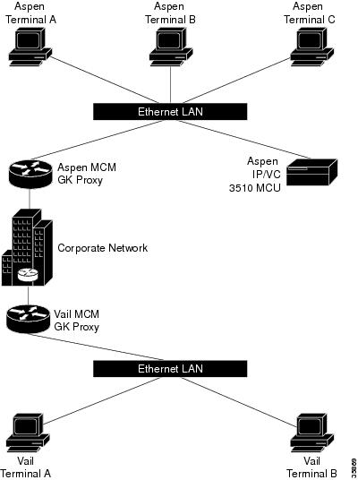
The following example is of an interzone calling configuration with two zones defined as Aspen and Vail.
Figure 1 Interzone Calling Configuration with Two Zones
The terminals are H.323 terminals.
The definitions for the above are as follows:
•
•
•
•
•
•
•
•
•
•
•
•
Every device with Aspen in its name is registered with the Aspen gatekeeper, and every device with Vail in its name is registered with the Vail gatekeeper.
The following is the configuration for Aspen MCM GK Proxy:
Hostname Aspen_MCM_GK_ProxyProxy h323interface Ethernet0/0ip address 10.0.0.1 255.0.0.0h323 interfaceh323 qos ip-precedence 6h323 h323-id aspen-proxyh323 gatekeeper id aspen ipaddr 10.0.0.1gatekeeperzone local aspen cisco.com 10.0.0.1zone remote vail cisco.com 12.0.0.1zone prefix aspen 11zone prefix vail 12use-proxy aspen default outbound-from gatewayno shutdownThe following is the configuration for Vail MCM GK Proxy:
Hostname Vail_MCM_GK_ProxyProxy h323interface Ethernet0/0ip address 10.0.0.1 255.0.0.0h323 interfaceh323 qos ip-precedence 6h323 h323-id vail-proxyh323 gatekeeper id vail ipaddr 12.0.0.1gatekeeperzone local vail cisco.com 12.0.0.1zone remote aspen cisco.com 10.0.0.1zone prefix aspen 11zone prefix vail 12gw-type-prefix 60 hopoff aspengw-type-prefix 61 hopoff aspengw-type-prefix 62 hopoff aspenuse-proxy aspen default outbound-from gatewayno shutdownIn this example, any terminal registered with the Aspen or Vail gatekeeper may participate in a multiparty call with any participant in either zone. For example, Aspen Terminal A could have a conference with Aspen Terminal C and Vail Terminal A by dialing 61555**33**1221. The conference prefix is 61, the conference password is 555, the invite is **, the E.164 address of Aspen Terminal C is 33, the zone prefix to reach the Vail zone is 12, and the E.164 address of Vail Terminal A is 21.
Alternatively, each terminal could independently dial 61555 to join the conference.
Command Reference
This section documents new or modified commands. All other commands used with this feature are documented in the Cisco IOS Release 12.1 command reference publications.
•
Note
bandwidth
To specify the maximum aggregate bandwidth for H.323 traffic, use the bandwidth gatekeeper configuration command. To disable, use the no form of this command.
bandwidth {interzone | total | session} {default | zone zone-name} bandwidth-size
no bandwidth {interzone | total | session} {default | zone zone-name} bandwidth-size
Syntax Description
Defaults
None
Command Modes
Gatekeeper configuration
Command History
11.3(2)NA
The zone bw command was introduced.
12.1(5)T
The bandwidth command replaces the zone bw command.
Usage Guidelines
In previous Cisco IOS software releases, the functionality of the bandwidth command was obtained by using the zone bw gatekeeper command.
Examples
The following example configures the default maximum bandwidth for all zones to 5,000 kbps:
Router(config)# gatekeeperRouter(config-gk)# bandwidth total default 5000Related Commands
bandwidth remote
To specify the total bandwidth for H.323 traffic between this gatekeeper and any other gatekeeper, use the bandwidth remote gatekeeper configuration command. To disable, use the no form of this command.
bandwidth remote bandwidth-size
no bandwidth remote bandwidth-size
Syntax Description
Defaults
None
Command Modes
Gatekeeper configuration
Command History
11.3(2)NA
The zone remote command was introduced.
12.1(5)T
The bandwidth remote command replaces the zone remote command.
Usage Guidelines
In previous Cisco IOS software releases, the functionality of the bandwidth remote command was obtained by using the zone remote gatekeeper command.
Examples
The following example configures the remote maximum bandwidth to 100,000 kbps:
Router(config)# gatekeeperRouter(config-gk)# bandwidth remote 100000Related Commands
h323 interface
To select an interface whose IP address will be used by the proxy to register with the gatekeeper, use the h323 interface interface configuration command. To use the default port, use no h323 interface and then h323 interface.
h323 interface [port number]
no h323 interface [port number]
Syntax Description
Defaults
Default port number is image dependent; see the Syntax Description table above.
Command Modes
Interface configuration
Command History
11.3(2)NA
This command was introduced.
12.1(5)T
The ability to specify the proxy port number was added.
Usage Guidelines
At proxy startup, the code checks for the presence of the VoIP gateway subsystem. If the subsystem is found to be present, the proxy code opens and listens for call setup requests on the new port. The proxy then registers this port with the gatekeeper.
Examples
The following example show how to configure Ethernet interface 0 (e0) for incoming call setup requests:
Router(config)# interface e0Router(config-if)# h323 interfaceRelated Commands
h323 t120
To enable the T.120 capabilities on your router and to specify bypass or proxy mode, use the h323 t120 interface configuration command.
h323 t120 {bypass | proxy}
Syntax Description
Defaults
Bypass mode
Command Modes
Interface configuration
Command History
Usage Guidelines
The no form of this command has no function—the only possible commands are h323 t120 bypass and h323 t120 proxy.
Examples
The following example shows how to enable the T.120 capabilities in proxy mode:
Router(config)# proxy h323Router(config)# interface e0Router(config-if)# h323 t120 proxyRelated Commands
show gatekeeper status
To show overall gatekeeper status that includes authorization and authentication status, zone status, and so on, use the show gatekeeper status command in EXEC mode.
show gatekeeper status
Syntax Description
This command has no arguments or keywords.
Defaults
No default behavior or values.
Command Modes
EXEC
Command History
11.3(2)NA and 12.0(3)T
This command was introduced.
12.1(5)T
Remote bandwidth output was added.
Examples
The following is sample output from the show gatekeeper status command:
router# show gatekeeper statusGatekeeper State: UPZone Name: gk-px4.cisco.comAccounting: DISABLEDSecurity: DISABLEDMaximum Remote Bandwidth:Table 1 describes the fields contained in the show gatekeeper status sample output.
Related Commands
show gatekeeper zone status
To display the status of zones related to a gatekeeper, use the show gatekeeper zone status command in privileged EXEC mode.
show gatekeeper zone status
Syntax Description
This command has no arguments or keywords.
Defaults
No default behavior or values.
Command Modes
Privileged EXEC
Command History
11.3(2)NA
This command was introduced.
12.0(5)T
This display format was modified for H.323 Version 2.
12.1(5)T
Bandwidth information added.
Usage Guidelines
Use this command to display the status of all zones related to a gatekeeper.
Examples
The following is an example from the show gatekeeper zone status command:
router# show gatekeeper zone statusGATEKEEPER ZONES================GK name Domain Name RAS Address PORT FLAGS MAX-BW CUR-BW(kbps) (kbps)------- ----------- ----------- ---- ----- ------ ------sj.xyz.com xyz.com 1.14.93.85 1719 LS 0BANDWIDTH INFORMATION (kbps) :Maximum interzone bandwidth :Current interzone bandwidth : 0Maximum total bandwidth :Current total bandwidth : 0Maximum session bandwidth :SUBNET ATTRIBUTES :All Other Subnets :(Enabled)PROXY USAGE CONFIGURATION :inbound Calls from germany.xyz.com :to terminals in local zone sj.xyz.com :use proxyto gateways in local zone sj.xyz.com :do not use proxyOutbound Calls to germany.xyz.comfrom terminals in local zone germany.xyz.com :use proxyfrom gateways in local zone germany.xyz.com :do not use proxyInbound Calls from all other zones :to terminals in local zone sj.xyz.com :use proxyto gateways in local zone sj.xyz.com :do not use proxyOutbound Calls to all other zones :from terminals in local zone sj.xyz.com :do not use proxyfrom gateways in local zone sj.xyz.com :do not use proxytokyo.xyz.co xyz.com 172.21.139.89 1719 RS 0milan.xyz.co xyz.com 171.69.57.90 1719 RS 0Table 2 describes the fields contained in the show gatekeeper zone status sample output.
Related Commands
show proxy h323 status
To display the overall status of a proxy, use the show proxy h323 status command in privileged EXEC mode.
show proxy h323 status
Syntax Description
This command has no arguments or keywords.
Defaults
No default behavior or values.
Command Modes
Privileged EXEC
Command History
11.3(2)NA and 12.0(3)T
This command was introduced.
12.1(5)T
Proxy IP address and port number added
Examples
The following is sample output from the show proxy h323 status command:
router# show proxy h323 statusH.323 Proxy Status==================H.323 Proxy Mode: EnabledProxy interface = Serial1: UP Proxy interface = Ethernet0:UPProxy IP address = 172.28.129.50Proxy IP port = 11720Application Specific Routing: DisabledRAS Initialization: CompleteProxy aliases configured:H323_ID: px2Proxy aliases assigned by Gatekeeper:H323_ID: px2Gatekeeper multicast discovery: DisabledGatekeeper:Gatekeeper ID: gk.zone2.comIP address: 70.0.0.31Gatekeeper registration succeededT.120 Mode: BYPASSRTP Statistics: OFFNumber of calls in progress: 1RTP StatisticsTable 3 describes the fields contained in the show proxy h323 status sample output.
Related Commands
show proxy h323 calls
Shows a list of each active call on the proxy.
show proxy h323 detail-call
Displays the details of a particular call on the proxy.
Glossary
AAA—Authorization, authentication, and accounting.
ABR—Available bit rate.
ASR—Application Specification Routing.
ATM—Asynchronous Transfer Mode. The ATM module command-line interface (CLI) uses a subset of the Cisco IOS software commands. Generally, the Cisco IOS software works the same on the ATM module as it does on routers.
BGP—Border Gateway Protocol.
gatekeeper—A gatekeeper maintains a registry of devices in the multimedia network. The devices register with the gatekeeper when they start up, and request admission to a call from the gatekeeper.
gateway—Gateways allow H.323 terminals to communicate with non-H.323 terminals by converting protocols.
H.225.0—An ITU standard that governs H.323 session establishment and packetization. H.225.0 actually describes several different protocols: Registration, Admission, and Status protocol (RAS); use of Q.931,;and use of Real-Time Transport Protocol (RTP).
H.245—An ITU standard that governs H.323 endpoint control.
H.323—An International Telecommunication Union (ITU) standard that describes packet-based video, audio, and data conferencing. H.323 is an umbrella standard that describes the architecture of the conferencing system, and refers to a set of other standards (H.245, H.225.0, and Q.931) to describe its actual protocol.
H.323 terminal—Endpoints in the multimedia network that provide real-time, two-way communications with another H.323 terminal. H.323 terminals are typically computer-based video conferencing systems.
MCM—Multimedia Conference Manager. Provides both gatekeeper and proxy capabilities, which are required for service provisioning and management of H.323 networks.
MCU— Multipoint control unit. An endpoint on the LAN that provides the capability for three or more terminals and gateways to participate in a multipoint conference.
NAT—Network Address Translation.
NMS—Network management system.
node—An H.323 entity that uses Registration, Admission, and Status protocol (RAS) to communicate with the gatekeeper; for example, an endpoint such as a terminal, proxy, or gateway.
PAT—Port Address Translation.
proxy—Special gateways that relay one H.323 session to another.
PVC—Permanent virtual circuit.
Q.931—An ITU standard that describes ISDN signaling. The H.225.0 standard uses a variant of Q.931 to establish and disconnect H.323 sessions.
QoS—Quality of service. Prioritizes network traffic with IEEE 802.1P class of service (CoS) values that allow network devices to recognize and deliver high-priority traffic in a predictable manner. When congestion occurs, QoS drops low-priority traffic to allow delivery of high-priority traffic.
RAI—Resource Availability Indication.
RAS—Registration, Admission, and Status protocol. This is the protocol used between endpoints and the gatekeeper.
RTP—Real-Time Transport Protocol. An IETF standard protocol. The H.225.0 standard describes how to use RTP to handle the packetization of video and audio in H.323.
RSVP—Resource Reservation Protocol. Protocol that supports the reservation of resources across an IP network. Applications running on IP end systems can use RSVP to indicate to other nodes the nature (bandwidth, jitter, maximum burst, and so forth) of the packet streams they want to receive. RSVP depends on IPv6. Also known as Resource Reservation Setup Protocol.
SNMP—Simple Network Management Protocol.
SVC—switched virtual circuit. Virtual circuit that is dynamically established on demand and is torn down when transmission is complete. SVCs are used in situations where data transmission is sporadic. Called a switched virtual connection in ATM terminology.
T.120—An ITU standard that describes data conferencing. H.323 provides for the ability to establish T.120 data sessions inside an existing H.323 session.
VBR—variable bit rate. QoS class defined by the ATM Forum for ATM networks. VBR is subdivided into a real time (RT) class and non-real time (nRT) class. VBR (RT) is used for connections in which there is a fixed timing relationship between samples. VBR (nRT) is used for connections in which there is no fixed timing relationship between samples, but that still need a guaranteed QoS.
VoFR—Voice over Frame Relay.
VoIP—Voice over IP. Voice over IP enables a router to carry voice traffic (for example, telephone calls and faxes) over an IP network.