Downloads |
 Feedback Feedback
|
Contents
- Overview of Easy Virtual Network
- Finding Feature Information
- Prerequisites for Configuring EVN
- Restrictions for EVN
- Information About EVN
- Benefits of EVN
- Virtual Network Tags Provide Path Isolation
- Virtual Network Tag
- vnet Global
- Edge Interfaces and EVN Trunk Interfaces
- Virtual Network Subinterface and Convention for Identifying a Trunk Interface in Display Output
- Single IP Address on Trunk Interface
- Relationship Between VRFs Defined and VRFs Running on a Trunk Interface
- VRF Awareness
- Routing Protocols Supported by EVN
- Packet Flow in a Virtual Network
- Command Inheritance on EVN Trunk Interfaces
- Overriding Command Inheritance Virtual Network Interface Mode
- Example Overriding Command Inheritance
- Example Applying an Attribute to vnet Global Only
- Removing Overrides and Restoring Values Inherited From EVN Trunk
- What Determines If the No Form of a Command Will Appear in a Configuration File
- EXEC Routing Context
- EVN Compatibility with VRF-Lite
- Multiaddress Family VRF Structure
- Commands Whose Values Can be Inherited Or Overridden by a Virtual Network on an Interface
- Additional References
- Feature Information for Overview of Easy Virtual Network
Overview of Easy Virtual Network
Easy Virtual Network (EVN) is an IP-based virtualization technology that provides end-to-end virtualization of two or more Layer-3 networks. You can use a single IP infrastructure to provide separate virtual networks whose traffic paths remain isolated from each other.
EVN builds on the existing IP-based virtualization mechanism known as VRF-Lite. EVN provides enhancements in path isolation, simplified configuration and management, and improved shared service support. EVN is backward compatible with the VRF-Lite solution to enable seamless network migration from VRF-Lite to EVN.
EVN supports IPv4, static routes, OSPFv2, and EIGRP for unicast routing, and PIM and MSDP for IPv4 Multicast routing. EVN also supports CEF and SNMP.
Finding Feature Information
Your software release may not support all the features documented in this module. For the latest feature information and caveats, see the release notes for your platform and software release. To find information about the features documented in this module, and to see a list of the releases in which each feature is supported, see the Feature Information Table at the end of this document.
Use Cisco Feature Navigator to find information about platform support and Cisco software image support. To access Cisco Feature Navigator, go to www.cisco.com/go/cfn. An account on Cisco.com is not required.
Prerequisites for Configuring EVN
- Implementing EVN in your network requires that you have a single IP infrastructure that you want to virtualize into two or more logical networks or L3VPNs, utilizing EVN. EVN will provide path isolation for the traffic on the different virtual networks.
- You must have a functioning campus design in place before adding virtualization to the network.
- You should understand virtual routing and forwarding (VRF) instances and how they are used to maintain traffic separation across the network.
Restrictions for EVN
- An EVN trunk is allowed on any interface that supports 802.1q encapsulation, such as Fast Ethernet and Gigabit Ethernet.
- There are additional platform and line-card restrictions for the trunk. You will need to check Cisco Feature Navigator for supported platforms and line cards.
- A single IP infrastructure can be virtualized to provide up to 32 virtual networks end to end.
- If an EVN trunk is configured on an interface, you cannot configure VRF-Lite on the same interface.
- OSPFv3 is not supported;OSPFv2 is supported.
-
The following are not supported:
- IS-IS
- RIP
- Route replication is not supported with BGP
- certain SNMP set operations
-
The following are not supported on an EVN trunk:
- access control lists (ACLs)
- BGP interface commands are not inherited
- IPv6 (except that IPv6 is supported on vnet global)
- NAT
- NetFlow
- WCCP
Information About EVN
- Benefits of EVN
- Virtual Network Tags Provide Path Isolation
- Virtual Network Tag
- vnet Global
- Edge Interfaces and EVN Trunk Interfaces
- Virtual Network Subinterface and Convention for Identifying a Trunk Interface in Display Output
- Single IP Address on Trunk Interface
- Relationship Between VRFs Defined and VRFs Running on a Trunk Interface
- VRF Awareness
- Routing Protocols Supported by EVN
- Packet Flow in a Virtual Network
- Command Inheritance on EVN Trunk Interfaces
- Overriding Command Inheritance Virtual Network Interface Mode
- Removing Overrides and Restoring Values Inherited From EVN Trunk
- EXEC Routing Context
- EVN Compatibility with VRF-Lite
- Multiaddress Family VRF Structure
- Commands Whose Values Can be Inherited Or Overridden by a Virtual Network on an Interface
Benefits of EVN
Easy Virtual Network is an IP-based virtualization technology that provides end-to-end virtualization over Layer-3 networks. Network virtualization can be used as a tool to secure a network, and a way to reduce network capital and operational expenses by utilizing the same network infrastructure for multiple virtual networks. A customer can leverage the same physical infrastructure multiple times by supporting multiple groups, each with their own logical network and unique routing and forwarding tables.
Prior to network virtualization, customers had the following ways to achieve path isolation:
- Provide physical separation by using dedicated routers per group, which is more expensive than virtual networks.
- Use access control lists (ACLs), but ACLs do not support unique routing and forwarding tables, can be expensive to maintain, and can be more error-prone than virtual networks.
EVN provide the following benefits:
- Reduced capital expenditures by not having to maintain separate physical infrastructures to keep traffic isolated. One IP network has two or more virtual networks with path isolation of the traffic in the networks, thereby saving the expense of additional hardware.
- Increased business flexibility, by easing the network integration of mergers, acquisitions, and business partners.
- Reduced complexity by decreasing the infrastructure requirements for maintaining traffic separation through the core of the network.
- They build on the existing mechanism known as Multi-VRF (VRF-Lite). EVN is compatible with VRF-Lite. See the EVN Compatibility with VRF-Lite section. EVN is recommended over VRF-Lite because EVN provides enhancements in path isolation, simplified configuration and management, and improved shared service support.
- In addition to maintaining traffic separation between business units within a company, there are other scenarios in which path isolation would be beneficial. Some examples follow:
- Guest access to the Internet--Restricting the guestâs network access to the Internet, using a predetermined data path through the customerâs network, and being able to define a unique default route for Guest Internet bound traffic.
- Network Admission Control (NAC) isolation--Isolating the traffic sourced from a noncompliant desktop.
- Partner access--Restricting partners and contractors to access network shared services that the customer allows, such as Internet, e-mail, DNS, DHCP, or an application server.
- Application and device isolation--Securing Data Center services and devices by âforcingâ traffic to a centralized firewall where the traffic is subject to inspection.
- Outsourcing services--Separating data traffic of various clients from each other.
- Scalable network--Restricting a portion of the network to traffic that requires a very strict service level, which can lower costs by providing those requirements only where needed.
- Subsidiaries/mergers/acquisitions--Consolidating companies or networks in stages, while enabling them to share services, when required.
- Enterprise acting as a service provider--Autonomous groups each requiring a separate network under a single authority. An example is an airport authority supporting a virtual network per airline.
Virtual Network Tags Provide Path Isolation
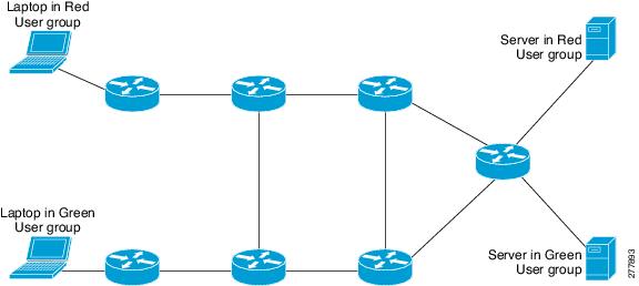
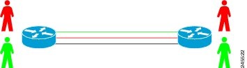
It is not uncommon to have different user groups running on the same IP infrastructure. Various business reasons require traffic isolation between the different groups. The figure below shows two user groups, Red and Green, running on the same network. Prior to network virtualization, there is no separation of traffic between the two groups. Users in the Red user group can access the server in the Green user group, and vice versa.
Without network virtualization, path isolation can be achieved by using access control, which is expensive to maintain, error-prone, and does not support unique routing and forwarding tables per network.
Virtual networks provide a coarse-grained segmentation of different user groups on one physical network. By configuring virtual networks, you can virtualize a single IP infrastructure to provide a number of virtual networks end to end. In the figure below, a single IP infrastructure is virtualized into two Virtual Private Networks (VPNs) by creating two VRFs, Red and Green.
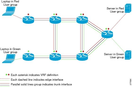
In addition to utilizing VRFs to provide device-level separation, each virtual network has path isolation from the other. The path isolation is achieved by tagging the traffic explicitly. The traffic carries the same tag value throughout the same virtual network. Each network device along the path uses the tags to provide separation among different VRFs. A single tag number ties VRF red, for example, on one router to VRF red on another router.
Virtual Network Tag
Each VPN and associated EVN has a tag value that you assign during configuration. The tag value is global, meaning that on each router, the same EVN must be assigned the same numerical tag value. Tag values range from 2 to 4094. An EVN is allowed on any interface that supports 802.1q encapsulation, such as Fast Ethernet and Gigabit Ethernet. To allow for backward compatibility with the VRF-Lite solution, the vLAN ID field in the 802.1q frame is used to carry the virtual network tag.
Traffic that carries a virtual network tag is called tagged traffic. Traffic that does not carry a virtual network tag is called untagged traffic.
Tags are illustrated in the following configuration with two VRFs, red and green. The two VRFs would each have their own tag, so the configuration of the tags on a router might look like this:
! Define two VRFs, red and green.
vrf definition red
 vnet tag 101
!
 address-family ipv4
 exit-address-family
!
vrf definition green
 vnet tag 102
!
 address-family ipv4
 exit-address-family
!
As can be seen, a virtual network is defined as a VRF instance with a virtual network tag assigned.
vnet Global
A predefined EVN known as âvnet globalâ is on the router. It refers to the global routing context and it corresponds to the default RIB. In the figure above and the figure below, vnet global is represented by the black line connecting routers. The vnet global carries untagged traffic. By default, interfaces belong to the vnet global. Furthermore, vnet global is always running on trunk interfaces. The vnet global is also known as the default routing table.
IPv6 traffic is supported in vnet global only.
Edge Interfaces and EVN Trunk Interfaces
User devices are connected to a Layer 2 switch port, which is assigned to a VLAN. A VLAN can be thought of as a Layer 2 VPN. Customers will group all of the devices that need to be supported in a common L3VPN in a single VLAN. The point where data traffic is handed off between a VLAN and VRF is called an edge interface.
- An edge interface connects a user device to the EVN and in effect defines the boundary of the EVN. Edge interfaces connect end devices such as hosts and servers that are not VRF-aware. Traffic carried over the edge interface is untagged. The edge interface classifies which EVN the received traffic belongs to. Each edge interface is configured to belong to only one EVN.
- An EVN trunk interface connects VRF-aware routers together and provides the core with a means to transport traffic for multiple EVNs. Trunk interfaces carry tagged traffic. The tag is used to de-multiplex the packet into the corresponding EVN. A trunk interface has one subinterface for each EVN. An interface is defined as an EVN trunk interface by the vnet trunk command.
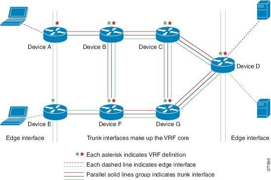
An EVN interface uses two types of interface: edge interfaces and trunk interfaces. An interface can be either an edge or trunk interface, but not both. The figure below illustrates Routers A and D have edge interfaces that belong to VRF Red. Routers D and E have edge interfaces that belong to VRF Green.
Routers B, C, D, F, and G have trunk interfaces that make up the EVN core. These five routers have interfaces that belong to both VRF Red and VRF Green.
Virtual Network Subinterface and Convention for Identifying a Trunk Interface in Display Output
Because a trunk interface carries multiple EVNs, sometimes it is not sufficient to display only the trunk interface name. When it is necessary to indicate that display output pertains to a particular EVN running on the trunk interface, the convention used is append a period and the virtual network tag, making the format <interface>.<virtual-network-tag>. Examples are gigabitethernet1/1/1.101 and gigabitethernet1/1/1.102.
By default, when a trunk interface is configured, all of the EVNs and associated virtual network tags are configured, and a virtual network subinterface is automatically created. As stated above, a period and the virtual network tag number are appended to the interface number.
In the following example, VRF red is defined with virtual network tag 3. Hence, the system created Fast Ethernet 0/0/0.3 (in VRF red).
Router# show running-config vrf red
Building configuration...
Current configuration : 1072 bytes
vrf definition red
 vnet tag 3
 !
 address-family ipv4
 exit-address-family
 !
You can display this hidden interface with the show derived-config command and see that all of the commands entered on Fast Ethernet 0/0/0 have been inherited by Fast Ethernet 0/0/0.3:
Router# show derived-config interface fastethernet0/0/0.3
Derived configuration : 478 bytes
!
interface FastEthernet0/0/0.3
 description Subinterface for VRF NG red
 vrf forwarding red
 encapsulation dot1Q 3
 ip address 10.1.1.1 255.255.255.0
 ip authentication mode eigrp 1 md5
 ip authentication key-chain eigrp 1 x
 ip bandwidth-percent eigrp 1 3
 ip hello-interval eigrp 1 6
 ip hold-time eigrp 1 18
 no ip next-hop-self eigrp 1
 no ip split-horizon eigrp 1
 ip summary-address eigrp 1 10.0.0.0 255.0.0.0
end
Single IP Address on Trunk Interface
A trunk interface can carry traffic for multiple EVNs. To simplify the configuration process, all the subinterfaces and associated EVNs have the same IP address assigned. In other words, the trunk interface is identified by the same IP address in different EVN contexts. This is accomplished as a result of each EVN having a unique routing and forwarding table, thereby enabling support for overlapping IP addresses across multiple EVNs.
Relationship Between VRFs Defined and VRFs Running on a Trunk Interface
By default, the trunk interfaces on a router will carry traffic for all VRFs defined by the vrf definition command. For example, in the following configuration, every VRF defined on the router is included on this interface:
interface FastEthernet 1/0/0
 vnet trunk
 ip address 10.1.1.1 255.255.255.0
However, you might want to enable only a subset of VRFs over a certain trunk interface for traffic separation purposes. This is achieved by creating a VRF list, which is referenced in the vnet trunk command. When a trunk interface is enabled with a VRF list, only VRFs on the list are enabled on the interface. The exception is that vnet global is always enabled on the trunk interface.
In the following example, only the two specified VRFs on the list (red and green) are enabled on this interface:
vrf list mylist
 member red
 member green
!
interface FastEthernet 1/0/0
 vnet trunk list mylist
 ip address 10.1.1.1 255.255.255.0
VRF Awareness
A device connected to a virtual network may not understand virtual network tags and can send and receive only untagged traffic. Such a device is referred to as VRF unaware. For example, a laptop computer is usually VRF unaware.
By contrast, a device that can send and receive tagged traffic and therefore takes the tag value into account when processing such traffic is known as VRF aware. For example, a VRF-aware server shared among different EVNs could use the virtual network tag to distinguish request received and send responses accordingly. A VRF-aware device is connected to the EVN using a trunk interface, as shown in the figure below.
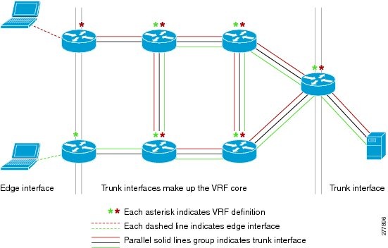
The term âVRF awareâ can also be used to describe a software component running on the router. A software component is VRF aware if it can operate on different EVNs. For example, ping is VRF aware because it allows you to choose which EVN to send the ping packet over.
Routing Protocols Supported by EVN
Each EVN runs a separate instance of a routing protocol. This allows each EVN to fine-tune its routing separately and also limits fate sharing. Different virtual networks may run different routing protocols concurrently.
EVN supports static routes, OSPFv2, and EIGRP for unicast routing, and PIM, MSDP, and IGMP for multicast routing.
Packet Flow in a Virtual Network
Packets enter an EVN through an edge interface, traverse multiple trunk interfaces, and exit the virtual network through another edge interface. At the ingress edge interface, packets are mapped from a VLAN into a particular EVN. Once the packet is mapped to an EVN, it is tagged with the associated virtual network tag. The virtual network tag allows the trunk interface to carry packets for multiple EVNs. The packets remain tagged until they exit the EVN through the egress edge interface.
On the edge interface, the EVN associated with the interface is used for route lookup. On the trunk interface, the virtual network tag carried in the packet is used to locate the corresponding EVN for routing the packets.
If the egress interface is an edge interface, the packet is forwarded untagged. However, if the egress interface is a trunk interface, the packet is forwarded with the tag of the ingress EVN.
The figure below illustrates how traffic from two VRFs, red and green, can coexist on the same IP infrastructure, using the tags 101 and 102.
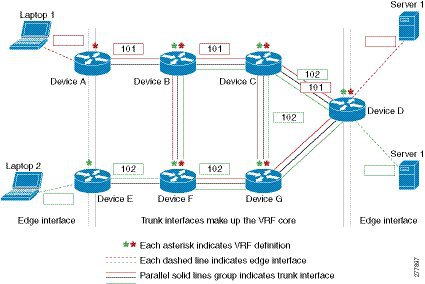
The packet flow from Laptop 1 to Server 1 in VRF red occurs as follows:
- Laptop 1 send an untagged packet to Server 1.
- Router A receives the packet over an edge interface, which is associated with VRF red.
- Router B receives the packet over a trunk interface. Seeing virtual network tag 101, Router B identifies that the packet belongs to VRF red.
- Router C receives the packet over a trunk interface. Using virtual network tag 101, Router C identifies that the packet belongs to VRF red.
- Router D receives the packet over a trunk interface. Using virtual network tag 101, Router D identifies that the packet belongs to VRF red.
- Server 1 receives the untagged packet originated from Laptop 1.
Command Inheritance on EVN Trunk Interfaces
One of the benefits of EVN is the ability to easily configure multiple EVNs on a common, trunk interface, without the need to configure each interface associated with an EVN individually. An EVN trunk interface takes advantage of the fact that the configuration requirements for different EVNs will be similar over a single trunk interface. When specific commands are configured on the trunk interface, they define default values that are inherited by all EVNs running over the same interface, including vnet global. If you feel that these settings are acceptable for all of the EVNs sharing an interface, then no individual configuration per EVN for those features is necessary.
For example, the OSPF hello interval can be set for all EVNs over the trunk interface with one line of configuration, as follows:
interface gigabitethernet1/1/1
 vnet trunk
 ip address 10.1.2.1 255.255.255.0
 ! set OSPF hello interval for all VRFs on this interface.
 ip ospf hello-interval 20
The list of commands configured on the trunk interface whose values are inherited by all EVNs running on the same interface is provided in the table in the section Commands Whose Values Can be Inherited Or Overridden by a Virtual Network on an Interface.
For more examples of command inheritance, see the configuration examples in the Configuring Easy Virtual Networks module.
Overriding Command Inheritance Virtual Network Interface Mode
You might want some EVNs on the same trunk interface to have different configurations. An alternative to command inheritance is to selectively override inherited values by using specific commands in virtual network interface mode for individual EVNs. In this mode, the commandâs settings override the Cisco default value or the value you set in interface configuration mode.
From interface configuration mode, entering the vnet name command causes the system to enter virtual network interface mode. The system prompt for this mode is Router(config-if-vnet)#.
The list of commands whose inherited values can be overridden is provided in the table in the section Commands Whose Values Can be Inherited Or Overridden by a Virtual Network on an Interface.
Example Overriding Command Inheritance
In the following example, the cost of 30 for VRF blue overrides the cost of 20 for the other VRFs on the interface:
interface gigabitethernet 2/0/0
 vnet trunk
 ip address 10.1.1.1 255.255.255.0
 ! Set OSPF cost for all VRFs on this interface to 20.
 ip ospf cost 20
vnet name blue
 description Subinterface for VRF NG blue
 ! Set OSPF cost for blue to 30.
 ip ospf cost 30
The show derived command indicates the subinterface changed to a cost of 30:
Router(config-if-vnet)# do show derived | s interface GigabitEthernet2/0/0

interface GigabitEthernet2/0/0
vnet trunk
ip address 10.1.1.1 255.255.255.0
ip ospf cost 20
interface GigabitEthernet2/0/0.200
description Subinterface for VRF NG blue
vrf forwarding blue
ip address 10.1.1.1 255.255.255.0
ip ospf cost 30
Router(config-if-vnet)#
Example Applying an Attribute to vnet Global Only
Similarly, you might want to enable an attribute on vnet global only. To do so, use the vnet global interface submode, as follows:
interface gigabitethernet1/1/1
 vnet trunk
 ip address 10.1.2.1 255.255.255.0
 vnet global
  ! Set OSPF cost for global to 40.
  ip ospf cost 40
In this example, a user wants an EIGRP interface attribute set for all EVNs except vnet global. All EVNs inherit a hold time of 20 seconds, except vnet global, which overrides 20 with a hold time of 40 seconds.
interface fastethernet 1/0/0
 vnet trunk
 ip address 10.1.3.1 255.255.255.0
 ip hold-time eigrp 1 20
 vnet global
 ip hold-time eigrp 1 40
Removing Overrides and Restoring Values Inherited From EVN Trunk
The no and default keywords result in different outcomes, depending on whether they are used for a trunk interface or in virtual network interface mode. This section describes the different outcomes.
- When the no or defaultkeyword is entered before a command on a trunk interface, the trunk is restored to the systemâs default value for that command. (This is standard behavior resulting from the no or defaultkeyword).
- When the defaultkeyword is entered before a command in virtual network interface mode, the override value is removed and the value that is inherited from the trunk is restored. The override value for the specific EVN is no longer in effect.
In the following example, the trunk interface is configured with an OSPF cost of 20, but VRF blue overrides that value with an OSPF cost of 30:
interface gigabitethernet 2/0/0
 vnet trunk
 ip address 10.1.1.1 255.255.255.0
 ! Set OSPF cost for all VRFs on this interface to 20.
 ip ospf cost 20
vnet name blue
 ! Set OSPF cost for blue to 30.
 ip ospf cost 30
When the following commands are entered, the OSPF cost value is restored to 20, which is the cost inherited from the trunk interface. (Note that 20 is not the default value of the ip ospf cost command).
Router(config-if)# vnet name blue
Router(config-if-vnet)# default ip ospf cost
The default keyword entered before a command in virtual network interface mode restores the default state, but the no keyword does not always do that. In the following example, no ip dampening-change eigrp 1 disables dampening change.
interface Ethernet1/1
 vnet trunk
 ip dampening-change eigrp 1 50
 shutdown
 vnet name red
  no ip dampening-change eigrp 1
! Make sure vnet red does NOT have dampening change enabled, regardless of trunk setting. !
What Determines If the No Form of a Command Will Appear in a Configuration File
If a command is the type of command that switches a feature on or off, the no form of the command will appear in the configuration file when configured. That is, it will be NVGENâed to override the setting from the EVN trunk, as shown in the following example:
interface gigabitethernet 2/0/0
 vnet trunk
 ip access-group 1 in
 vnet name red
  no ip pim sparse-mode
  no ip route-cache cef
  no ip access-group in
 vnet global
  ip ospf cost 100
If a command takes an argument in its the syntax, such as ip ospf cost cost , the no form of the command will remove the configuration, but does not appear in the configuration file. That is, it will not be NVGENâed because the user could enter ip ospf cost default-value to override the inherited value in a more direct way.
EXEC Routing Context
There may be occasions when you want to issue several EXEC commands to apply to a single EVN. In order to reduce the repetitive entering of VRF names for multiple EXEC commands, the routing-context vrf command allows you to set the VRF context of such EXEC commands once, and then proceed with EXEC commands.
The table below contrasts four EXEC commands in Cisco IOS without routing context and in routing context. Note that in the left column, each EXEC command must identify the VRF. In the right column, the VRF content is identified once and the prompt changes to reflect that VRF; there is no need to identify the VRF in each command.
|
Cisco IOS CLI Without Routing Context |
Routing Context |
|---|---|
|
-- |
Router# routing-context vrf red
Router%red#
|
Router# show ip route vrf red
[Routing table output for VRF red] |
Router%red# show ip route
[Routing table output for VRF red] |
Router# ping vrf red 10.1.1.1
[Ping result using VRF red] |
Router%red# ping 10.1.1.1
[Ping result using VRF red] |
Router# telnet 10.1.1.1 /vrf red
[Telnet to 10.1.1.1 in VRF red] |
Router%red# telnet 10.1.1.1
[Telnet to 10.1.1.1 in VRF red] |
Router# traceroute vrf red 10.1.1.1
[Traceroute output in VRF red] |
Router%red# traceroute 10.1.1.1
[Traceroute output in VRF red] |
EVN Compatibility with VRF-Lite
EVN is wire compatible with VRF-Lite. In other words, from outside the box, the use of 802.1q, the SNMP MIBs, and all the infrastructure will look exactly the same as VRF-Lite.
In the figure below, both routers have VRFs defined. The router on the left uses VRF-Lite, and the router on the right uses an EVN trunk with tags. The two configurations follow the figure.
VRF-Lite Subinterface Configuration EVN Trunk Configuration
interface TenGigabitEthernet1/1/1                  interface TenGigabitEthernet 1/1/1
 ip address 10.122.5.31 255.255.255.254             vnet trunk
 ip pim query-interval 333 msec                     ip address 10.122.5.32 255.255.255.254
 ip pim sparse-mode                                 pim sparse-mode
 logging event link-status                          logging event link-status
interface TenGigabitEthernet1/1/1.101              Global Configuration:
 description Subinterface for Red VRF              vrf definition red
 encapsulation dot1Q 101                            vnet tag 101
 ip vrf forwarding Red
 ip address 10.122.5.31 255.255.255.254            vrf definition green
 ip pim query-interval 333 msec                     vnet tag 102
 ip pim sparse-mode
 logging event subif-link-status
interface TenGigabitEthernet1/1/1.102
 description Subinterface for Green VRF
 encapsulation dot1Q 102
 ip vrf forwarding Green
 ip address 10.122.5.31 255.255.255.254
 ip pim query-interval 333 msec
 ip pim sparse-mode
 logging event subif-link-status
Multiaddress Family VRF Structure
Prior to Cisco IOS Releases 12.2(33)SB and 15.0(1)M, the CLI for a VRF applied to only one address family at a time. For example, the following command applies only to the IPv4 address family:
ip vrf blue
In Cisco IOS Releases 12.2(33)SB and 15.0(1)M, the CLI for a VRF applies to multiple address families under the same VRF. This is known as multiprotocol VRF. For example, the following command applies to IPv4 and IPv6 VPNs at the same time. The routing tables for the two protocols are still different.
vrf definition blue
 Note | In Cisco IOS XE Release 3.2S, virtual networks do not support IPv6 except in vnet global. |
Commands Whose Values Can be Inherited Or Overridden by a Virtual Network on an Interface
As explained in the Command Inheritance on EVN Trunk Interfaces section, there are interface commands that can defined once for a trunk interface, and the value is inherited by each EVN sharing that interface. These commands are sometimes referred to as trunk commands.
A subset of the trunk commands are commands whose values can be overridden by specifying the command in virtual network interface mode. This is explained in the Overriding Command Inheritance Virtual Network Interface Mode section.
The table below lists interface commands and indicates whether the values are inherited by the EVNs on the interface and whether the commands can be overridden for a specific EVN.
|
Values Inherited by EVNs on Interface? |
Values Can Be Overriden in Virtual Network Interface Mode? |
|
|---|---|---|
|
IP Commands |
||
|
ip accounting |
Yes |
No |
|
ip address |
Yes |
No |
|
ip broadcast-address |
Yes |
No |
|
ip directed broadcast |
Yes |
No |
|
ip information-reply |
Yes |
No |
|
ip irdp |
Yes |
No |
|
ip load-sharing |
Yes |
No |
|
ip mask-reply |
Yes |
No |
|
ip mtu |
Yes |
No |
|
ip proxy-arp |
Yes |
No |
|
ip redirects |
Yes |
No |
|
ip unnumbered |
Yes |
No |
|
ip unreachables |
Yes |
No |
|
EIGRP Commands |
||
|
ip authentication key-chain eigrp |
Yes |
Yes |
|
ip authentication mode eigrp |
Yes |
Yes |
|
ip bandwidth-percent eigrp |
Yes |
Yes |
|
ip dampening-change eigrp |
Yes |
Yes |
|
ip dampening-interval eigrp |
Yes |
Yes |
|
ip hello-interval eigrp |
Yes |
Yes |
|
ip hold-time eigrp |
Yes |
Yes |
|
ip next-hop-self eigrp |
Yes |
Yes |
|
ip split-horizon eigrp |
Yes |
Yes |
|
ip summary-address eigrp |
Yes |
Yes |
|
Commands that affect how EIGRP determines cost for an interface |
||
|
bandwidth (interface) |
Yes |
Yes |
|
delay (interface) |
Yes |
Yes |
|
OSPF Commands |
||
|
ip ospf process-id area |
No |
Yes |
|
ip ospf authentication |
Yes |
Yes |
|
ip ospf authentication-key |
Yes |
Yes |
|
ip ospf bfd |
Yes |
Yes |
|
ip ospf cost |
Yes |
Yes |
|
ip ospf database-filter |
Yes |
Yes |
|
ip ospf dead-interval |
Yes |
Yes |
|
ip ospf demand-circuit |
Yes |
Yes |
|
ip ospf flood-reduction |
Yes |
Yes |
|
ip ospf hello-interval |
Yes |
Yes |
|
ip ospf lls |
Yes |
Yes |
|
ip ospf message-digest-key |
Yes |
Yes |
|
ip ospf mtu-ignore |
Yes |
Yes |
|
ip ospf network |
Yes |
Yes |
|
ip ospf priority |
Yes |
Yes |
|
ip ospf resync-timeout |
Yes |
Yes |
|
ip ospf shutdown |
Yes |
Yes |
|
ip ospf transmit-delay |
Yes |
Yes |
|
ip ospf transmit-interval |
Yes |
Yes |
|
ip ospf ttl-security |
Yes |
Yes |
|
ip ospf vnet area |
No |
No |
|
IP Multicast Commands |
||
|
ip igmp access-group |
Yes |
Yes |
|
ip igmp explicit-tracking |
Yes |
Yes |
|
ip igmp helper-address |
Yes |
Yes |
|
ip igmp immediate-leave |
Yes |
Yes |
|
ip igmp last-member-query-count |
Yes |
Yes |
|
ip igmp last-member-query-interval |
Yes |
Yes |
|
ip igmp limit |
Yes |
Yes |
|
ip igmp mroute-proxy |
Yes |
Yes |
|
ip igmp proxy-service |
Yes |
Yes |
|
ip igmp querier-timeout |
Yes |
Yes |
|
ip igmp query-interval |
Yes |
Yes |
|
ip igmp query-max-response-time |
Yes |
Yes |
|
ip igmp tcn |
Yes |
Yes |
|
ip igmp unidirectional-link |
Yes |
Yes |
|
ip igmp v3lite |
Yes |
Yes |
|
ip igmp version |
Yes |
Yes |
|
ip multicast boundary |
Yes |
Yes |
|
ip pim bidir-neighbor-filter |
Yes |
Yes |
|
ip pim bsr-border |
Yes |
Yes |
|
ip pim dense-mode |
Yes |
Yes |
|
ip pim dr-priority |
Yes |
Yes |
|
ip pim nbma-mode |
Yes |
Yes |
|
ip pim neighbor-filter |
Yes |
Yes |
|
ip pim passive |
Yes |
Yes |
|
ip pim query-interval |
Yes |
Yes |
|
ip pim sparse-dense-mode |
Yes |
Yes |
|
ip pim sparse-mode |
Yes |
Yes |
|
ip pim state-refresh |
Yes |
Yes |
|
Multicast Forwarding Information Base (MFIB) Commands |
||
|
ip mfib cef |
Yes |
Yes |
|
ip mfib forwarding |
Yes |
Yes |
Additional References
Related Documents
|
Related Topic |
Document Title |
|---|---|
|
Cisco IOS commands |
|
|
Easy Virtual Network commands |
Easy Virtual Network Command Reference |
|
Configuring Easy Virtual Network |
âConfiguring Easy Virtual Networkâ module in the Easy Virtual Network Configuration Guide. |
|
Configuring Easy Virtual Network shared services and route replication |
âConfiguring Easy Virtual Network Shared Servicesâ module in the Easy Virtual Network Configuration Guide. |
|
Easy Virtual Network management and troubleshooting |
âEasy Virtual Network Management and Troubleshootingâ module in the Easy Virtual Network Configuration Guide. |
MIBs
Technical Assistance
|
Description |
Link |
|---|---|
|
The Cisco Support and Documentation website provides online resources to download documentation, software, and tools. Use these resources to install and configure the software and to troubleshoot and resolve technical issues with Cisco products and technologies. Access to most tools on the Cisco Support and Documentation website requires a Cisco.com user ID and password. |
Feature Information for Overview of Easy Virtual Network
The following table provides release information about the feature or features described in this module. This table lists only the software release that introduced support for a given feature in a given software release train. Unless noted otherwise, subsequent releases of that software release train also support that feature.
Use Cisco Feature Navigator to find information about platform support and Cisco software image support. To access Cisco Feature Navigator, go to www.cisco.com/go/cfn. An account on Cisco.com is not required.
|
Feature Name |
Releases |
Feature Information |
|---|---|---|
|
Easy Virtual Network Trunk |
Cisco IOS Release XE 3.2S |
Easy Virtual Network is an IP-based virtualization technology that provides end-to-end virtualization of the network. You can use a single IP infrastructure to provide separate virtual networks whose traffic paths remain isolated from each other. |
Cisco and the Cisco Logo are trademarks of Cisco Systems, Inc. and/or its affiliates in the U.S. and other countries. A listing of Cisco's trademarks can be found at www.cisco.com/go/trademarks. Third party trademarks mentioned are the property of their respective owners. The use of the word partner does not imply a partnership relationship between Cisco and any other company. (1005R)
Any Internet Protocol (IP) addresses and phone numbers used in this document are not intended to be actual addresses and phone numbers. Any examples, command display output, network topology diagrams, and other figures included in the document are shown for illustrative purposes only. Any use of actual IP addresses or phone numbers in illustrative content is unintentional and coincidental.