Using the PMC Application

Table Of Contents

Using the PMC Application

Scenarios for Using the PMC Application

Cisco IPICS Server-PMC Interaction Scenario

Incident Management Scenario

PMC User Interaction

Supported Features

Voice Interoperability

Channel Support

Channel Terminology

The Role of the Cisco IPICS Server

Implementing Policies

Location Support

Codec Support

Logging In to the PMC Application

Login Caveats

License Information

Server-PMC Login Sequence Interaction

PMC Offline Mode Caveats

PMC Login Procedure

Using the PMC Application

Accessing Online Help

Dynamic Configuration

Channel Interaction/Features

Cisco IPICS Server Commands

Support for Maximum Number of Channels

End-user Channel Interaction

Joining a VTG

Activating the PMC Buttons

Traffic Activity

Channel Traffic Activity Interaction

User Channel Activity Interaction

Logging Out of the PMC Application


Using the PMC Application


This chapter provides information about using the PMC, including logging in and logging out of the application. It also includes information about supported features and specific terminology that the Cisco IPICS solution uses.

This chapter includes the following sections:

Scenarios for Using the PMC Application

Supported Features

Logging In to the PMC Application

Using the PMC Application

Logging Out of the PMC Application

Scenarios for Using the PMC Application

The following scenarios show how the Cisco IPICS solution combines the server and the PMC to enable voice interoperability. This section describes the following topics:

Cisco IPICS Server-PMC Interaction Scenario

Incident Management Scenario

PMC User Interaction

Cisco IPICS Server-PMC Interaction Scenario

The following sequence of events shows how the Cisco IPICS server interacts with the PMC user, and includes information about the tasks that are performed by the various Cisco IPICS user roles:

1. The Cisco IPICS system administrator sets up the Cisco IPICS server from which the PMC user can download and install the PMC application. The system administrator also sets up and imports the user preference themes, which include graphics, XML, and tones for the PMC.

The PMC retrieves the PMC installation file from the Cisco IPICS server along with the PMC user configuration data.

2. The Cisco IPICS operator sets up the users and the channels for the PMC user.

3. The Cisco IPICS dispatcher assigns the channels to the PMC user and sets up the talk groups by activating and deactivating the VTGs.

4. The PMC user downloads and installs the PMC application. For more information, see the "Downloading and Installing the PMC Application" section.

The Cisco IPICS server checks the license count for concurrent license usage. See the "License Information" section for information about licenses for concurrent PMC usage.

5. The PMC user initiates a session with the server by using the PMC application. See the "Launching the PMC Application" section.

During the login sequence, the server provides information to the PMC about available versions to ensure compatibility. For more information, see the "Managing PMC Version Numbers" section.

6. The PMC sends a request to the server to authenticate the user. See the "Server-PMC Login Sequence Interaction" section.

7. After successful authentication, the server uses the unique PMC ID to track requests and to manage the session with the PMC. The following activities can occur during these sessions:

a. The server can execute a command or update the configuration on the PMC.

b. At regular intervals, and as configured in the server, the PMC can check with the server for updates.

8. The PMC retrieves a personalized list of channels from the server, along with the configuration settings that provide user-specific customization information, including the order preference for displaying the channels. See the "Channel Interaction/Features" section.

9. The PMC user may perform minimal PMC customization, such as setting the PMC skin. For more information about customizing the PMC, see the "Customizing the PMC End-User Interface" section.

After the PMC changes are saved, the PMC sends the updated configuration settings to the server.

10. The PMC user can use only the voice channels that the dispatcher assigns. The PMC user can choose to activate any of the assigned channels.


Note The PMC only displays those channels that have been assigned by the dispatcher. If your ability to transmit on a channel has been disabled by the server, the PTT button will not highlight. If the channel has been disabled by the server, you will not be able to activate the channel.


The PMC user may also be able to communicate and interact with the dispatcher through a policy channel which may be configured as a designated channel that remains always open on the PMC.

As a PMC user, you could use this policy channel, if it is configured, to initiate a request to the dispatcher to set up a new VTG when the situation arises. For more information about policies, see the "Implementing Policies" section.

11. The PMC user clicks the Activate button on the PMC application to directly join the channel. The Activate button highlights and the system attempts to connect to the Cisco IPICS server. After the connection has been established, the remaining PMC buttons, including the PTT channel button, highlight to indicate that they are in an active state. (If your ability to transmit on a channel has been disabled by the server, the PTT button will not highlight.)

The type of connection that Cisco IPICS uses depends on the configuration that the PMC retrieved from the server. The PMC connection types include remote connection by using SIP-based trunking into the RMS component (which is directly tuned into the multicast channel) and multicast connection by directly tuning into the multicast channel. See the "Location Support" section for more information about these types of connections.

12. The PMC user can listen in and talk on one or more channels at the same time. In this case, the PMC mixes the audio on the PMC client machine so that the PMC user can join multiple VTGs simultaneously.


Note Be aware that you may experience echo when you simultaneously listen to a VTG and a channel that is bound to that VTG.


Tip The PTT latch functionality provides the ability to talk on multiple channels at the same time. To latch, or lock in, the PTT button, position your cursor over the PTT button and then press the Shift key while you click the left mouse button. Follow this procedure for each channel that you want to talk on. To clear the latch, press the PTT button without holding the Shift key.

Be aware that when you latch the PTT button, this action blocks transmissions from half-duplex radios when these devices are attached to the channel or VTG via an LMR gateway.


13. The PMC checks the server for updates at regular intervals. When an update occurs (such as the activation or deactivation of a VTG), the PMC retrieves the updated information from the server.


Note Based on the updates from the server, the PMC display refreshes automatically to reflect the changes that were made by the dispatcher (such as the activation of a new VTG or the deactivation of a VTG that has ended).


14. The PMC logs the details of the channel assignments, including activation and deactivation. At predefined intervals, the Cisco IPICS server retrieves these logs from the PMC. See the "Using the PMC Logs" section for more information about the logging facility.

Incident Management Scenario

In a Cisco IPICS scenario, the occurrence of an event or incident leads to the creation and activation of a VTG. The dispatcher can perform this VTG setup on an ad hoc (as needed) basis or by preconfiguring the VTG. Preconfigured VTGs could be scheduled to run at defined intervals or activated on demand.

The following example portrays an incident management scenario that shows how the various Cisco IPICS system components work together to deliver the Cisco IPICS solution.

1. The dispatcher receives a 911 emergency call and creates a voice channel that correlates to a specific incident.

2. With a simple drag-and-drop operation on the Cisco IPICS server administration console, the dispatcher includes the police department in the talk group.

3. By using the PMC application, the dispatcher communicates directly with the police officer at the scene by using push-to-talk (PTT) functionality.

4. Upon discovering the magnitude of the emergency, the police officer informs the dispatcher of the need to communicate directly with the fire department.

5. Again, with a simple drag-and-drop operation on the Cisco IPICS server administration console, the dispatcher adds the fire department into the talk group.

6. The police officer, dispatcher, and the fire department are all included in the expanded VTG and they are enabled to use PTT capabilities to communicate with each other.

7. Next, as a decision is made to dispatch fire engines to the scene, the dispatcher communicates with the public utility department and adds their radio channel into the talk group. During this time, the participants who are included in the talk group can make real-time decisions about items such as road conditions, routes to follow, and any necessary lane clearances.

8. Finally, the dispatcher seamlessly patches the enterprise security team and the facilities team, who use their own radio channels, into the talk group and they discuss evacuation procedures with all of the various agencies that are included in the call.

PMC User Interaction

The PMC user interacts with the PMC to join the VTG by clicking the PMC buttons after the dispatcher assigns channels to the user.

1. The PMC retrieves the personalized list of voice channels that the dispatcher assigns. The order of the channels, as they display on the PMC, is determined by the server. (The PMC display refreshes automatically based on the configuration that it retrieves from the Cisco IPICS server. If a channel has been disabled by the server, you will not be able to activate the channel.)

2. The PMC user clicks the Activate button on the PMC application to turn on and join in the VTG.

3. The Activate button highlights and the system attempts to connect to the Cisco IPICS server. After the connection has been established, the remaining PMC buttons, including the PTT button, highlight to indicate that they are in an active state. (If your ability to transmit on a channel has been disabled by the server, the PTT button will not highlight.)

4. The PMC user clicks the PTT button to talk and releases the button to invoke listen-only mode.

5. When the incident has ended, the dispatcher deactivates the VTG; the server automatically refreshes the PMC, based on the new configuration, and removes the VTG from the PMC application.

Related Topics

Cisco IPICS System Components

Architecture/Deployment

Launching the PMC Application

Location Support

Server-PMC Login Sequence Interaction

Channel Interaction/Features

Joining a VTG

Activating the PMC Buttons

Supported Features

This release of Cisco IPICS provides support for the following features:

Voice Interoperability

Channel Support

Location Support

Codec Support

Voice Interoperability

Cisco IPICS solves the problem of voice interoperability between disparate systems by bridging PTT communications between multiple LMR systems, IP phones, and the Cisco IPICS PMC.

As a PC-based software application, the PMC comprises a stand-alone LMR PTT audio application that enables users, and dispatch and administrative personnel to participate in one or more VTGs at the same time.

Figure 3-1 shows an illustration of the various components that interoperate with the Cisco IPICS solution.

Figure 3-1 Cisco IPICS Interoperability Solution

For more information about the Cisco IPICS components, see the
"Cisco IPICS System Components" section.

For information about Cisco IPICS deployment, see the "Architecture/Deployment" section.

Channel Support

This section includes information about the types of channels that Cisco IPICS supports. It describes the following topics:

Channel Terminology

The Role of the Cisco IPICS Server

Implementing Policies

Channel Terminology

Channels form the fundamental building blocks of all the talk groups in the Cisco IPICS solution. Each channel contains a PTT button with send/receive feedback, volume control, and an activation control button that toggles on and off.

Table 3-1 describes the terminology that Cisco IPICS uses.

Table 3-1 Cisco IPICS Terminology 

Term
Description

Channel

A channel consists of a single unidirectional or bidirectional path for sending and/or receiving signals. In the Cisco IPICS solution, a channel represents one LMR gateway port that maps to a conventional radio physical radio frequency (RF) channel.

Note If a name, or label, has been configured in the server for the PTT button, that name displays in the channel area as part of the PTT button on the PMC. The name may change, based on the configuration in the Cisco IPICS server.

Talk Group

A talk group comprises a subgroup of radio users who, under normal circumstances, only coordinate actions amongst users who are in the same talk group; radio interface with other subgroups is not required.

With Cisco IPICS, a channel maps to a logical talk group; that is, all the participants who talk on the same radio frequency belong to a talk group

Virtual Talk Group

A virtual talk group, or VTG, represents interoperability of a group of channels and maps to a voice channel that users attach to based on a specific incident. The PMC directly joins the VTG based on the location configuration that is configured in the server. See the "Location Support" section for more information.

In this release of Cisco IPICS, a VTG represents an audio meeting.

Virtual Channel

A virtual channel is similar to a channel but a radio system may not be attached. By creating a virtual channel, participants who do not use physical handheld radios to call into a VTG become enabled by using the PMC application or Cisco IP Phone 7960 or Cisco IP Phone 7970.


The Role of the Cisco IPICS Server

Cisco IPICS authorized personnel register, assign, activate, and deactivate channels in the Cisco IPICS server. These activities affect the channel, configuration, and connection information for your PMC in addition to the level of your user privileges.

The channel name, or label, that displays in the channel area as part of the PTT button on your PMC represents a logical name that the administrator assigns to the channel and defines in the server.


Note If the channel name includes more characters than what the PMC can display, the PMC truncates the name and adds an ellipsis (...) next to the name.


The PMC retrieves the channel information, along with other configuration data, when the server sends notification to the PMC about the availability of the channel. The order in which the channels display on the PMC is determined by the server.

The system administrator performs most of the configuration tasks for the PMC application; however, you may customize the PMC skin for your own "look and feel." To customize the PMC skin, navigate to the Settings > Skin menu on the PMC.


Note To access the Skin submenu, move your cursor so that it is positioned over the PMC that displays on your desktop; then, right-click anywhere inside the PMC window and click Settings > Skin. For more information about customizing the PMC skin, see the "Customizing the PMC End-User Interface" section.


The Cisco IPICS server contains the associated connection configuration, which correlates to locations, to determine how the PMC should connect. Cisco IPICS provides connection support for both multicast and unicast communications.

Multicast refers to communications that are sent between a single sender and multiple recipients on a network.


Note Be sure to pre-qualify your PMC client machine for multicast communications. Certain Windows 2000 and Windows XP PMC client machines may encounter issues with sending multicast communications; in these situations, the PMC client machine may be able to receive but not transmit traffic. For more information, see the "Troubleshooting Multicast Communications Issues" section.


Unicast refers to communications that are sent between a single sender and a single recipient on a network.


Note For more information about choosing your location and your type of connection, see the "Location Support" section.

For more information about the multicast technology, refer to the following URL: http://www.cisco.com/warp/public/732/Tech/multicast/.


The Cisco IPICS server maintains the user privileges for each PMC user.

These privileges extend to the list of PMC channels that you can view and use.

When the dispatcher activates a VTG for you, you obtain privileges to all channels in that VTG for the duration of the VTG.

After the dispatcher deactivates a VTG that has ended, the PMC display refreshes automatically, based on the updates that it receives from the server, and removes the VTG from your PMC.

Implementing Policies

Cisco IPICS includes the functionality to create/update/delete, enable/disable, and execute/run policies. Policies associate events or triggers to an action.

The following list includes the events or triggers that can initiate a policy:

Selecting a button on the PMC

Explicitly triggering a policy (this action can be done by the dispatcher from the administration console)

Using time-based triggering

Policies can include a set sequence of actions, such as activating VTGs.

Cisco IPICS provides the functionality for the dispatcher to predefine these policies. By using policies, talk groups can be quickly set up or predefined to operate on a regular basis.

Dispatcher Channel

The dispatcher may also set up a policy channel by which you can communicate through the PMC. This policy channel, if it is configured and designated by the dispatcher on the PMC, acts as a channel that is always open and enables your interaction with the dispatcher.

By using this channel on the PMC, you could initiate a request to the dispatcher to set up a new VTG when the situation arises.

Location Support

In the Cisco IPICS solution, location signifies "reachability;" that is, channels or users who are associated with the same location can communicate with each other without additional network configuration. Location is functionally equivalent to a multicast domain such that users who are in the same multicast domain are also in the same Cisco IPICS location.

The label that the system administrator configures in the Cisco IPICS server may refer to the location; this label could correspond to a physical or a virtual location.


Tip The location specifies the type of channel communication that is appropriate for the location. If you choose a location and you do not hear any voice traffic, choose a different location until you hear the audio on the channel. You can change your location by restarting the PMC and then choosing another available location from the drop-down list box in the location selection dialog box.


The system administrator specifies a location whenever a new channel, VTG, or user is added to the system.

1. The system administrator configures the channel and the location information in the Cisco IPICS server for each PMC user.

These location definitions correspond to the different locations from which a PMC user can access that channel.

2. As a PMC user, you can directly join the channel by using one of the following connection types:

a. Remote connection—This type of connection uses SIP-based trunking into the RMS component, which is directly tuned into the multicast channel. This communication flows over a unicast channel that establishes a point-to-point session with the RMS.

Cisco IPICS may deactivate channels that are connected via remote connection if there is no traffic activity after a specified time interval, as configured in the server. To reactivate a channel after it has been deactivated, click the Activate button on the PMC.

b. Multicast address/port—This type of connection enables the PMC to directly tune in to the multicast channel. See the "Troubleshooting Multicast Communications Issues" section for information about troubleshooting multicast communications.

3. Upon initial PMC login, the PMC retrieves the personalized channel list and list of defined locations from the server. A dialog box displays to prompt you to choose a location from the list. See the "Launching the PMC Application" section for more information about choosing your location.

This prompt occurs only one time per PMC instance and immediately after your initial login.

4. You choose a location that corresponds to the type of connection that you will use on that channel.

a. The server uses this location to specify the type of channel communication (SIP-based unicast or multicast) that is appropriate for the location.

b. In the event that you move to another location, the system allows you to explicitly change the location by choosing another available location.


Tip Your system administrator can provide instructions about how to choose the proper location. If you choose an incorrect location and you do not hear any voice traffic, choose a different location until you hear the audio on the channel. You can change your location by choosing another available location from the drop-down list box in the location selection dialog box.


Default Location

A default location may be defined for each PMC user.

As part of its configuration, the Cisco IPICS server communicates the default location to the PMC.

The PMC notifies the server about whether the default location, or another system-defined location, is being used.

The system preselects the default location, or the location that you most recently chose, in the list that displays in the location selection window.

Codec Support

Voice-compression algorithms are commonly referred to as codecs (coder/decoder). Coding involves the process of encoding a digitized signal into a more efficient form for transmission; decoding encompasses the process of restoring the coded signal to its original form.

Codecs differ in terms of voice quality, compression rate and bandwidth, ability to carry dual-tone multifrequency (DTMF) and modem traffic, and the number of channels (calls) that can be supported.

The Cisco IPICS server defines the codecs that the PMC uses on a per-channel basis and sends this information to the PMC. (The PMC may override the codec setting, if necessary.)

With this release, the PMC supports the following codecs:

G.711—G.711 performs pulse code modulation (PCM); it is the standard digital channel that is used in the public telephone network. PCM provides no compression and it does not require any digital signal processor (DSP) resources for transcoding.

G.729—G.729 is a medium complexity codec that compresses speech or audio signal components into 8-kbps streams. G.729 requires DSP resources for transcoding.


Note Be aware that misconfigured codecs can cause an audio problem on the PMC. For more information, see the "Resolving Codec Mismatch Issues" section.


For more information about VoIP per-call bandwidth requirements and guidelines, refer to Voice Over IP - Per Call Bandwidth Consumption at http://www.cisco.com/en/US/tech/tk652/tk698/technologies_tech_note09186a0080094ae2.shtml.

An interactive tool that provides guidance about how to calculate bandwidth requirements for packet voice calls is available by accessing the Voice Codec Bandwidth Calculator at http://tools.cisco.com/Support/VBC/do/CodecCalc1.do. This tool provides information about the bandwidth that is used by different codecs for various voice protocols over different types of media.

Related Topics

Cisco IPICS System Components

Architecture/Deployment

Launching the PMC Application

Location Support

Customizing the PMC End-User Interface

Troubleshooting Voice Quality Issues

Logging In to the PMC Application

As a PMC user, you initially log in to the PMC application by logging through the application in to the Cisco IPICS server. (The first login requires availability of the Cisco IPICS server.) The server validates the user login credentials so that subsequent PMC logins can be performed without the server.

See the "Launching the PMC Application" section for more information and an illustration of the login prompt window.

This section provides information about logging in to the PMC and includes the following topics:

Login Caveats

License Information

Server-PMC Login Sequence Interaction

Related Topics

Login Caveats

The following login caveats apply to this release of Cisco IPICS:

The Cisco IPICS system allows only one instance of the PMC application to be open and only one user to be logged in to the PMC application on the client machine at a given time.

If you need to log in to a PMC on a given client machine that already has another PMC user logged in, the original user must first log out of the application.

A PMC user can log in to an unlimited number of different PMC applications at the same time.

Any number of valid Cisco IPICS users can use the same PMC application, but not concurrently. See the "License Information" section.

The PMC application always logs in to the same Cisco IPICS server; that is, the server that has been configured as the default server and from which the PMC installation file has been downloaded. To change servers, you must reinstall the PMC application from a different Cisco IPICS server.

License Information

The Cisco IPICS server uses the PMC ID to track the version number of the PMC and to verify and manage concurrent PMC usage for licensing requirements.

Cisco IPICS uses the following criteria to determine license consumption for PMC users:

Cisco IPICS PMC Usage—A PMC user consumes a license each time that the user logs in to a PMC session.

If the same PMC user logs in to multiple PMC sessions from different PMC client machines, that user will consume multiple licenses (one for each PMC session).


Note If all Cisco IPICS licenses have been used, your access to the system will be interrupted. If this situation occurs, make sure that you contact your system administrator to request that additional user licenses be purchased and installed immediately.


Server-PMC Login Sequence Interaction

When you log in to the PMC, and when the connection between the server and the PMC is operational, your login request flows over a secure web (HTTPS) connection for processing by the Cisco IPICS server. If the connection between the server and the PMC is not operational, the system allows you to log in locally on your PMC client machine.


Note Cisco IPICS does not prevent you from logging in to the PMC application if the connection to the server goes offline.


This section describes the initial login sequence for the PMC user; it includes the following topics:

PMC Offline Mode Caveats

PMC Login Procedure

PMC Offline Mode Caveats

When the connection to the server goes offline, the PMC enters offline mode. Offline mode allows you to continue to communicate during periods of server downtime. The following caveats apply to the PMC offline mode:

You must have at least one successful login to the server before you can use the PMC in offline mode.

If the server goes offline while you are running the PMC, the system displays a message to alert you that the server is not available. The PMC enters offline mode with the current list of channels.

If the server is offline when you start the PMC, the system displays a message to alert you. The PMC enters offline mode with the last online session's list of channels. (Some channels may no longer work, depending on the connection type.)

After the server returns to an online state, you may encounter an invalid user or password error when you try to log in to the PMC. This situation may occur if the PMC attempts to connect to the server while the server database is being restored. In this case, the login dialog box may display several times until the server database has been fully restored.

If your user ID was deleted while the PMC was operating in offline mode, the system displays a message to inform you that your user name is not valid. The PMC then logs out and displays the normal startup login dialog box.

If the RMS entries become changed while you are running the PMC, your SIP channels may become disconnected. The PMC retrieves the updated channel list, with the newly-allocated SIP channels, after successful login to the server.

PMC Login Procedure

To log in to the PMC application, follow this procedure:

Procedure


Step 1 Double-click the PMC icon on your desktop or navigate to Start > Programs > Cisco IPICS > PMC to launch the application.

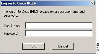
The Cisco IPICS login prompt displays.

Figure 3-2 shows an illustration of the Cisco IPICS login window.

Figure 3-2 Cisco IPICS Login Window

Step 2 To log in to the PMC, enter your user name and password; then, click OK.


Tip Be aware that user names and passwords are case-sensitive.


The PMC logs in to the Cisco IPICS server and sends this login information over a secure HTTPS connection.

If your login was successful, the server provides the ability for subsequent local logins.

If your login was not successful and you receive a failure notification because the PMC application could not communicate with the server, you can log in to the PMC locally, as long as you have already successfully logged in to the Cisco IPICS server.


Note If the PMC becomes disconnected from the Cisco IPICS server, it continues to operate in its existing state; that is, the PMC can continue with its existing voice channels but it cannot connect to other channels until it reconnects to the server.


Step 3 After successful login, the Cisco IPICS server checks the PMC version number.

If a PMC update is available for download, a message displays to alert you. If the update is not critical, you can choose to upgrade the PMC at a later time. See the "Performing a Noncritical Upgrade" section for more information.

If the system detects an incompatible version of the PMC, a message displays to alert you that the system must perform an upgrade immediately. See the "Performing a Critical Upgrade" section for more information.

If the PMC version is current, the server sends the list of locations that have been associated with your user ID.

Step 4 Choose your default location and your PMC version from the drop-down list boxes; then, click OK.


Note The PMC version drop-down list box includes the PMC versions that are compatible with the server.


Note The location information that displays in the drop-down list box is configured in the Cisco IPICS server. Contact your system administrator if your location information does not display as an option.


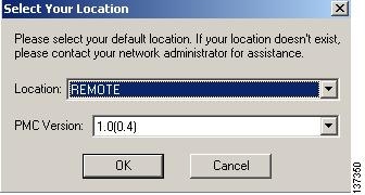
Figure 3-3 shows an illustration of the location selection dialog box.

Figure 3-3 Location Selection Dialog Box

Step 5 The PMC sends its location information to the server and requests its configuration updates.


Note The PMC sets the location once per login sequence, but the server may also process the location information through the updates that it receives from the PMC.


After the login has completed and the location has been set, the server maintains the PMC session information to ensure that only one session exists on the server for each PMC.

Step 6 The PMC retrieves the personalized list of visible channels/VTGs from the server.

A channel displays on the PMC when it has been assigned to you by the dispatcher. The server determines the order in which the channels appear.

A VTG displays on the PMC after it has been activated by the dispatcher; this activation begins the talk group and, at this point, you are placed into the active VTG.


Note You can only view and use those voice channels that the dispatcher has assigned to you. You can choose to turn on any of the assigned PTT channels by clicking the Activate button on the PMC. Channels that appear grayed-out on the PMC indicate that the channel/VTG is available and waiting for you to activate. If your ability to transmit on a channel has been disabled by the server, the PTT button will not highlight.


Step 7 Click the Activate button on the PMC application to directly join the VTG and hear the audio stream.


Tip When you click the Activate button immediately after a SIP-based (unicast) channel becomes available on the PMC, you may hear a busy tone if the RMS has not completely configured the channel. If you encounter this situation, click the Activate button to deactivate the channel; then, wait a few seconds and click Activate again to reactivate the channel. For more information about channel activation issues, see the "Identifying Channel Activation Issues" section.


After the PMC connects with the server, the channel on the PMC application becomes activated and appears highlighted to indicate that it is in an active state. (If your ability to transmit on a channel has been disabled by the server, the PTT button will not highlight.)

Step 8 Click the PTT button and hold it to talk.

The transmit graphical indicator blinks red to indicate that you are transmitting traffic.

Step 9 When you are done talking, release the left mouse button to return to listen-only mode.

The receive graphical indicator blinks green to indicate that you are receiving traffic. (This indicator remains illuminated for several seconds after the receive transmission has ended.)

To talk on one or more channels at the same time, you can use the PTT latch functionality. To latch, or lock in, the PTT channel, position your cursor over the PTT button and then press the Shift key while you click the left mouse button. Follow this procedure for each channel that you want to talk on. (The receive graphical indicator blinks green for the duration of the latch, whether you are talking or not.) To clear the latch, click the PTT button without holding the Shift key.


Caution Use the latch functionality with caution. Be aware that when you latch the PTT button, this action blocks transmissions from half-duplex radios when these devices are attached to the channel or VTG via an LMR gateway.

Related Topics

Architecture/Deployment

Upgrading the PMC Application

Performing a Noncritical Upgrade

Performing a Critical Upgrade

License Information

Using the PMC Application

This section provides information about how to use the PMC application and it also describes the various interactions that occur; it includes the following topics:

Accessing Online Help

Dynamic Configuration

Channel Interaction/Features

Traffic Activity

Accessing Online Help

To access online help for the PMC, follow this procedure:

Procedure


Step 1 Position your cursor over the PMC window that displays on your desktop.

Step 2 Right-click anywhere inside the PMC window; then, click Settings.

Step 3 Click Help. Alternatively, you can press F1 to access help.

The PMC online help information displays.


Figure 3-4 shows the Help link on the Cisco IPICS Mouse 4-Channel skin.

Figure 3-4 PMC 4-Channel Mouse Skin with Menu

Dynamic Configuration

This section describes the dynamic configuration that the Cisco IPICS server performs for the PMC application. It also includes information about the PMC update procedure. (See the "PMC Updates" section.)

The Cisco IPICS server manages the configuration for the PMC so you do not need to perform any configuration tasks. The server configuration includes information such as the system level PMC configuration, master skin distribution, user configuration, and channel definitions and authorized actions per channel.

In general, the PMC retrieves all configuration and channel connectivity data from the Cisco IPICS server, including a default theme and a skin/XML definition that is configured by the system administrator.

You can, however, customize the PMC skin by choosing from the available options that appear in the Settings menu. For more information about accessing the Settings menu to change the PMC skin, see the "Configuring the PMC Skins" section.


Note The Cisco IPICS server saves and stores all user configuration settings for use with each login.


PMC Updates

The PMC includes the ability to check the Cisco IPICS server for configuration changes (when the server is online); if the application status changes, the PMC securely connects to the server to update its current state.

At regular intervals, the PMC sends a status request to the server for each PMC user. This status request determines if the user configuration needs an update and/or if the server has a request for the PMC to execute certain commands (such as an update). If the user's configuration settings have changed, the PMC creates a secure HTTPS connection to the server for transmission of the updated information.


Note The Cisco IPICS system performs a user level update only when a valid PMC user is logged in to the PMC application.


Channel Interaction/Features

This section describes the channel interactions and features on the PMC; it also provides information about joining a VTG and using the PMC buttons.

This section includes the following topics:

Cisco IPICS Server Commands

Support for Maximum Number of Channels

End-user Channel Interaction

Joining a VTG

Activating the PMC Buttons

Cisco IPICS Server Commands

Table 3-2 describes the commands that can be sent from the Cisco IPICS server to the PMC in XML format.

Table 3-2 Cisco IPICS Server Commands 

Command
Description

Channel List

Upon log in to the server, the PMC retrieves the channel list from the server. This list includes the names of the channels that the dispatcher assigns for each PMC user along with the connection type (location information).

Note The PMC retrieves the entire channel list, even if the PMC has been configured to display fewer channels than that which is contained in the list. In the case of channel mismatch, the dispatcher receives a warning message when the PMC user may not be able to view all of the assigned channels/VTGs. See the "Skin Caveats" section for more information

Disable User

This command disables the PMC user from accessing the Cisco IPICS system. If the user is disabled while the PMC is online (communicating with the server), Cisco IPICS logs the user off the PMC after processing this command.

Disable Channel

This command disables one or more channels on the PMC. Channels that are in a disabled state appear as non-activated channels but they cannot be activated.

Retrieve Logs

This command retrieves the logs from the PMC.

Set Logging Level

This command turns on and off the individual logs on the PMC. It also sets the debug levels within the debug log.

Mute User

This command mutes a PMC user from talking or transmitting voice on one or more channels. (The system displays a pop-up message, along with a grayed out PTT channel button, to alert the user that permission to transmit has been revoked; if your ability to transmit on a channel has been disabled by the server, the PTT button will not highlight on the PMC).


Support for Maximum Number of Channels

With this release, the PMC supports a maximum of eight channels. This support includes the ability to simultaneously receive and/or talk on one or multiple channels.

You can use the PTT latch functionality to talk on one or more channels at the same time. To latch, or lock in, the PTT button, position your cursor over the PTT button and then press the Shift key while you click the left mouse button. Follow this procedure for each channel that you want to talk on. To clear the latch, click the PTT button without holding the Shift key.


Caution Use the latch functionality with caution. Be aware that when you latch the PTT button, this action blocks transmissions from half-duplex radios when these devices are attached to the channel or VTG via an LMR gateway.

You can customize the PMC skin to enable your own "look and feel," by choosing from one of the following skins as described in Table 3-3.

Table 3-3 Cisco IPICS PMC Skins 

Skin Label
Skin Description

Cisco IPICS Mouse 4-Channel

This skin displays 4 channels that you control with your mouse.

Cisco IPICS Mouse 8-Channel

This skin displays 8 channels that you control with your mouse.

Cisco IPICS Touch 4-Channel

This skin displays 4 channels in a touch screen format.

Cisco IPICS Touch 4-Channel Low Res

This skin displays 4 channels in a low resolution touch screen format. (For information about using the touch screen low resolution skins, see the "Configuring the PMC Skins" section.)

Cisco IPICS Touch 8-Channel

This skin displays 8 channels in a touch screen format.

Cisco IPICS Touch 8-Channel Low Res

This skin displays 8 channels in a low resolution touch screen format.


For more information and instructions about customizing the PMC skins, see the "Customizing the PMC End-User Interface" section.

See Figure 1-1 for an illustration of the Cisco IPICS Mouse 4-Channel skin.

See Figure 4-2 for an illustration of the Cisco IPICS Touch 4-Channel skin.

See Figure 4-5 for an illustration of the Cisco IPICS Mouse 4-Channel skin with the optional settings menu.

End-user Channel Interaction

As the Cisco IPICS stand-alone application, the primary goal of the PMC is to enable the PMC user to easily communicate on multiple PTT audio channels.

The PMC structure enables convenient and optimized interaction with multiple channels and different channel types. All channel types that the dispatcher has assigned and activated for your use appear on the PMC. You can selectively activate any of the assigned channels by clicking the Activate button on the PMC. (Channels that appear grayed out on the PMC indicate that the channel/VTG is available and waiting for you to activate. If the channel has been disabled, you will not be able to activate the channel.)


Note If your ability to transmit on a channel has been disabled by the server, the PTT button will not highlight.


Channels/States

Table 3-4 shows the VTG/channel states that Cisco IPICS supports for user interaction.

If a name, or label, has been configured in the server for the PTT button, that name displays in the channel area as part of the PTT button on the PMC. The name may change, based on the configuration in the Cisco IPICS server.

Table 3-4 End-User Channel Interaction States 

VTG/Channel State
PMC Button Indication
Description

Activating

The Activate button appears highlighted

This state becomes effective when you click the Activate button. The other PMC buttons remain in an inactive state as the system attempts to activate and connect.

Note If your ability to transmit on a channel has been disabled by the server, the PTT button will not highlight.

Activated

The PTT channel button and volume indicator appear highlighted

This state indicates that the SIP (unicast) or multicast channel is fully operational.

When a channel is enabled and activated, all of the PMC buttons are operational.

Not Activated

No PMC buttons appear highlighted

This state becomes effective when you click the Activate button again (to deactivate the channel) or if the connection terminates.

When a channel is enabled but not activated, the PTT channel button appears grayed-out but you may press the Activate button to activate the channel.

Disabled

No PMC buttons appear highlighted and you cannot activate the channel

When a channel is disabled, all of the PMC buttons are grayed-out or muted so that you cannot activate the channel. However, you can still view the channel or VTG label, if one was configured in the server.

Unassigned

No PMC buttons appear highlighted and you cannot activate the channel

A channel that is unassigned appears on the PMC with all of the buttons grayed-out and no channel name. You cannot activate or use an unassigned channel.


Joining a VTG

When you are logged in to the PMC and the dispatcher creates a new VTG for you to join, the PMC retrieves the channel list, which includes information about the VTG, from the Cisco IPICS server; the server automatically refreshes the PMC window to show the updated channels.

A corresponding alerting channel flashes on the PMC to let you know that you need to click the Activate button to join the VTG. (The channel on the PMC application becomes activated and appears highlighted to show that it is in an active state as long as your ability to transmit has not been disabled by the server.)

Click the highlighted PTT channel button and hold it to talk; transmission becomes enabled on the multicast stream. When you are done talking, release the left mouse button to return to listen-only mode.

See the "End-user Channel Interaction" section for information about the various channel states.

Figure 3-5 shows an illustration of the interaction with the PMC user.

Figure 3-5 Interaction with the PMC User

Activating the PMC Buttons

Each channel contains a PTT channel button with send/receive feedback, volume control, volume graphical indicator, and an activation control button that toggles on and off.

Table 3-5 describes the buttons that display on the PMC. Use your mouse to click, or push, these buttons to perform the corresponding function.

Table 3-5 PMC Button Icons 

Button Icon
Button Function
Button Description

PTT Channel

This is the PTT channel button and the PMC receive (green) and transmit (red) indicators. Click with your mouse, or push, the PTT button and hold it to talk. You can also latch this button to talk on one or more channels at the same time. To clear the latch, click the PTT button to release and return to listen-only mode.

Activation and Deactivation

Click this button to activate a channel (to call out); click again to deactivate a channel.

Volume Down

Click this button to decrease the volume on the channel.

Volume Up

Click this button to increase the volume on the channel.


Tip To latch, or lock in, the PTT button, position your cursor over the PTT button and then press the Shift key while you click the left mouse button. Follow this procedure for each channel that you want to talk on. To clear the latch, click the PTT button without holding the Shift key.


Caution Use the latch functionality with caution. When you latch the PTT button, this action blocks transmissions from half-duplex radios when these devices are attached to the channel or VTG via an LMR gateway.

The PMC provides the ability to individually control the volume on each channel. The volume slide bar controls the level of audio output for the specified channel as mixed with all other channels.

Figure 3-6 shows an illustration of the PMC buttons and the volume indicator bar as they appear on the application.

Figure 3-6 PMC Buttons


Note The volume level that the volume graphical indicator bar displays may appear slightly different depending on the granularity of the specific PMC skin that you use.


You can also use key assignments to quickly access these same buttons, and other features, by pressing keystroke sequences to activate the corresponding function.

Table 3-6 lists these keystrokes and the function that each one provides in Cisco IPICS release 10.

Table 3-6 PMC Button Accelerated Keystroke Assignments 

Channel Number on the PMC
Keystroke to Activate or Deactivate the Channel
Keystroke to Latch (lock in) or Unlatch the PTT Button
Keystroke to Increase the Volume
Keystroke to Decrease the Volume

Channel 1

Shift-1

1

q

a

Channel 2

Shift-2

2

w

s

Channel 3

Shift-3

3

e

d

Channel 4

Shift-4

4

r

f

Channel 5

Shift-5

5

t

g

Channel 6

Shift-6

6

y

h

Channel 7

Shift-7

7

u

j

Channel 8

Shift-8

8

i

k


Tip Be aware that the keystroke assignments are case-sensitive. Make sure that you do not have Caps Lock enabled when you use these keystroke assignments.


Note These keystroke assignments may be customized in the Cisco IPICS server; contact your administrator if the keystroke sequences that are shown in Table 3-6 do not function.


Traffic Activity

This section provides information about traffic and channel traffic activity interactions; it includes the following topics:

Channel Traffic Activity Interaction

User Channel Activity Interaction

The PMC supports the display of channel traffic activity (receive and transmit) along with the ability to tune in and tune out of the channel itself. To show traffic activity, the PMC provides graphical indicators. (See Figure 1-1 for an illustration of the PMC and the location of the graphical indicators.)

Although the PMC skins may be customized to define the actual colors that are used, the Cisco standard defines the following conventions for the receive and transmit indicators:

Table 3-7 Channel Traffic Activity Indicators 

Channel Traffic Activity Indicator
Description

Receive indicator

This graphical indicator blinks green when you are receiving traffic. This indicator remains illuminated for several seconds after the receive transmission has ended to let you know that the user has stopped talking.

Note When you latch the PTT button, the receive indicator blinks green for the duration of the latch whether you are talking or not.

Transmit indicator

This graphical indicator blinks red when you are transmitting traffic.


Tip These graphical indicators provide useful visual aids that enable clear identification of the PMC traffic streams. When you are talking, you should monitor the receive indicator to see if it is blinking. If the receive indicator is blinking, you may be talking over another user. If you encounter this situation, release the PTT button to release it and listen to the user who is talking. (To be sure that a user has stopped talking, wait for the receive indicator to display in a solid color format for a few seconds before you start to talk.)


Examples of how these indicators may appear are shown below:

The channel may blink green when it receives traffic from the network.

The channel may blink red when there is PTT transmission while the PTT control is activated.

Indicators for glare, a condition when a channel receives traffic while the PTT is active, may blink a different color.

A separate color may blink for situations where the bearer traffic is lost because of a system transmit/receive overflow.

When receive traffic activity displays, a graphical indicator reveals that traffic has occurred in the past on this channel; this feedback clears after five seconds.

Channel Traffic Activity Interaction

The following information describes the channel traffic activity interaction:

Both the channel name and the traffic activity feedback can be mapped to the PTT button in the server. This allows both of these indicators to display as part of the PTT button itself.

Cisco IPICS supports implicit floor control; that is, when Cisco IPICS wants to have the floor, the system assumes that the user will wait to generate traffic. The Cisco IPICS server considers the reception of traffic as a floor request.

The Cisco IPICS server has the ability to administratively stop the transmission of traffic onto a channel on a per-channel basis; in this situation, all transmission terminates immediately.

User Channel Activity Interaction

Your ability to view and use channels on the PMC depends on your user status.

You can only view and use those voice channels that the dispatcher has assigned to you.

You can choose to turn on any of the assigned PTT channels by clicking the Activate button on the PMC.

If you activate and deactivate channels on the PMC while you are actively using one of the channels, the audio on the channel that you are actively using may become distorted.

Channels that appear grayed-out on the PMC indicate that the channel/VTG is available and waiting for you to activate.

If your ability to transmit on a channel has been disabled by the server, the PTT button will not highlight.

If there is no traffic activity after a 30 minute interval, channels that are activated via a SIP-based remote connection may be deactivated by the system. The PMC will automatically reactivate the connection after 30 seconds. Alternatively, you can reactivate the channel by clicking the Activate button on the PMC.

When a channel is disabled, all of the PMC buttons are grayed-out or muted so that you cannot activate the channel. However, you can still view the channel or VTG label, if one was configured in the server.

A channel that is unassigned appears on the PMC with all of the buttons grayed-out and no channel name. You cannot activate or use an unassigned channel.


Note If you activate and deactivate channels while you are actively using one of the channels on the PMC, the audio on the channel that you are actively using may become distorted.


Related Topics

Configuring the PMC Skins

Skin Caveats

Logging Out of the PMC Application

You can log out of the PMC application by either clicking Exit from the PMC menu or by clicking the "X" that is located at the top right corner of the PMC application.

Figure 3-7 shows an illustration of the Cisco IPICS Mouse 4-Channel skin. It displays the Exit option on the Settings menu and the "X" on the PMC.

Figure 3-7 4-Channel PMC Skin

Where to Find More Information

Cisco IPICS Server Administration Guide