Feedback Feedback
|
Table Of Contents
Troubleshooting Fiber Distributed Data Interface
5
Troubleshooting Fiber Distributed Data Interface
The Fiber Distributed Data Interface (FDDI) standard was produced by the ANSI X3T9.5 standards committee in the mid-1980s. During this period, high-speed engineering workstations were beginning to tax the capabilities of existing local-area networks (LANs)—primarily Ethernet and Token Ring. A new LAN was needed that could easily support these workstations and their new distributed applications. At the same time, network reliability was becoming an increasingly important issue as system managers began to migrate mission-critical applications from large computers to networks. FDDI was developed to fill these needs.
After completing the FDDI specification, ANSI submitted FDDI to the International Organization for Standardization (ISO). ISO has created an international version of FDDI that is completely compatible with the ANSI standard version.
Although FDDI implementations are not as common as Ethernet or Token Ring, FDDI has gained a substantial following that continues to increase as the cost of FDDI interfaces diminishes. FDDI is frequently used as a backbone technology as well as a means to connect high-speed computers in a local area.
FDDI Technology Basics
FDDI specifies a 100-Mbps, token-passing, dual-ring LAN using a fiber-optic transmission medium. It defines the physical layer and media-access portion of the link layer, and is roughly analogous to IEEE 802.3 and IEEE 802.5 in its relationship to the Open System Interconnection (OSI) reference model.
Although it operates at faster speeds, FDDI is similar in many ways to Token Ring. The two types of networks share many features, including topology (ring), media-access technique (token passing), and reliability features (redundant rings, for example). For more information on Token Ring and related technologies, refer to Chapter 6, "Troubleshooting Token Ring."
One of the most important characteristics of FDDI is its use of optical fiber as a transmission medium. Optical fiber offers several advantages over traditional copper wiring, including security (fiber does not emit electrical signals that can be tapped), reliability (fiber is immune to electrical interference), and speed (optical fiber has much higher throughput potential than copper cable).
FDDI defines use of two types of fiber: single mode (sometimes called monomode) and multimode. Modes can be thought of as bundles of light rays entering the fiber at a particular angle. Single-mode fiber allows only one mode of light to propagate through the fiber, whereas multimode fiber allows multiple modes of light to propagate through the fiber. Because multiple modes of light propagating through the fiber may travel different distances (depending on the entry angles), causing them to arrive at the destination at different times (a phenomenon called modal dispersion), single-mode fiber is capable of higher bandwidth and greater cable run distances than multimode fiber. Because of these characteristics, single-mode fiber is often used for interbuilding connectivity, and multimode fiber is often used for intrabuilding connectivity. Multimode fiber uses light-emitting diodes (LEDs) as the light-generating devices, whereas single-mode fiber generally uses lasers.
FDDI Specifications
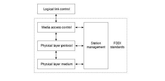
FDDI is defined by four separate specifications (see Figure 5-1):
•
Media Access Control (MAC)—Defines how the medium is accessed, including frame format, token handling, addressing, an algorithm for calculating a cyclic redundancy check value, and error recovery mechanisms.
•
•
•
Figure 5-1 FDDI Standards
Physical Connections
FDDI specifies the use of dual rings. Traffic on these rings travels in opposite directions. Physically, the rings consist of two or more point-to-point connections between adjacent stations. One of the two FDDI rings is called the primary ring; the other is called the secondary ring. The primary ring is used for data transmission, and the secondary ring is generally used as a backup.
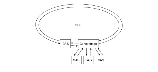
Class B or single-attachment stations (SASs) attach to one ring; Class A or dual-attachment stations (DASs) attach to both rings. SASs are attached to the primary ring through a concentrator, which provides connections for multiple SASs. The concentrator ensures that failure or power down of any given SAS does not interrupt the ring. This is particularly useful when PCs, or similar devices that frequently power on and off, connect to the ring.
A typical FDDI configuration with both DASs and SASs is shown in Figure 5-2.
Figure 5-2 FDDI Nodes: DAS, SASs, and Concentrator
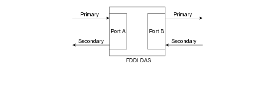
Each FDDI DAS has two ports, designated A and B. These ports connect the station to the dual FDDI ring. Therefore, each port provides a connection for both the primary and the secondary ring, as shown in Figure 5-3.
Figure 5-3 FDDI DAS Ports
Traffic Types
FDDI supports real-time allocation of network bandwidth, making it ideal for a variety of different application types. FDDI provides this support by defining two types of traffic: synchronous and asynchronous. Synchronous traffic can consume a portion of the 100-Mbps total bandwidth of an FDDI network, and asynchronous traffic can consume the rest. Synchronous bandwidth is allocated to those stations requiring continuous transmission capability. Such capability is useful for transmitting voice and video information, for example. Other stations use the remaining bandwidth asynchronously. The FDDI SMT specification defines a distributed bidding scheme to allocate FDDI bandwidth.
Asynchronous bandwidth is allocated using an eight-level priority scheme. Each station is assigned an asynchronous priority level. FDDI also permits extended dialogues, where stations may temporarily use all asynchronous bandwidth. The FDDI priority mechanism can essentially lock out stations that cannot use synchronous bandwidth and have too low an asynchronous priority.
Fault-Tolerant Features
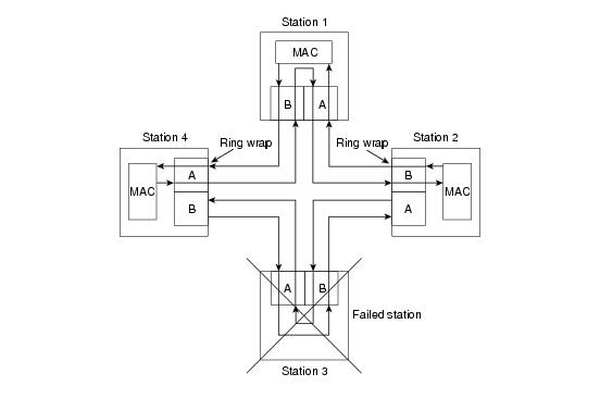
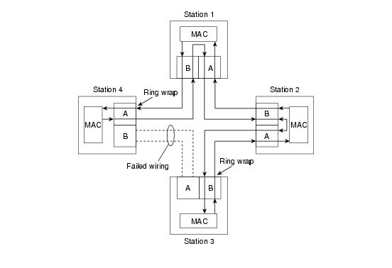
FDDI provides a number of fault-tolerant features, the most important of which is the dual ring. If a station on the dual ring fails or is powered down or if the cable is damaged, the dual ring is automatically wrapped (doubled back onto itself) into a single ring, as shown in Figure 5-4. In this figure, when Station 3 fails, the dual ring is automatically wrapped in Stations 2 and 4, forming a single ring. Although Station 3 is no longer on the ring, network operation continues for the remaining stations.
Figure 5-4 Station Failure, Ring Recovery Configuration
Figure 5-5 shows how FDDI compensates for a wiring failure. Stations 3 and 4 wrap the ring within themselves when wiring between them fails.
Figure 5-5 Failed Wiring, Ring Recovery Configuration
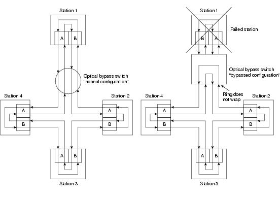
As FDDI networks grow, the possibility of multiple ring failures grows. When two ring failures occur, the ring is wrapped in both cases, effectively segmenting the ring into two separate rings that cannot communicate with each other. Subsequent failures cause additional ring segmentation.
Optical bypass switches can be used to prevent ring segmentation by eliminating failed stations from the ring. This is shown in Figure 5-6.
Figure 5-6 The Use of an Optical Bypass Switch
Critical devices such as routers or mainframe hosts can use another fault-tolerant technique called dual homing to provide additional redundancy and help guarantee operation. In dual-homing situations, the critical device is attached to two concentrators. One pair of concentrator links is declared the active link; the other pair is declared passive. The passive link stays in backup mode until the primary link (or the concentrator to which it is attached) is determined to have failed. When this occurs, the passive link is automatically activated.
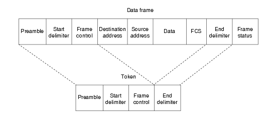
Frame Format
FDDI frame formats (shown in Figure 5-7) are similar to those of Token Ring.
Figure 5-7 FDDI Frame Format
The fields of an FDDI frame are as follows:
•
•
•
•
•
•
•
•
•
CDDI
The high cost of fiber-optic cable has been a major impediment to the widespread deployment of FDDI to desktop computers. At the same time, shielded twisted-pair (STP) and unshielded twisted-pair (UTP) copper wire is relatively inexpensive and has been widely deployed. The implementation of FDDI over copper wire is known as Copper Distributed Data Interface (CDDI).
Before FDDI could be implemented over copper wire, a problem had to be solved. When signals strong enough to be reliably interpreted as data are transmitted over twisted-pair wire, the wire radiates electromagnetic interference (EMI). Any attempt to implement FDDI over twisted-pair wire had to ensure that the resulting energy radiation did not exceed the specifications set in the United States by the Federal Communications Commission (FCC) and in Europe by the European Economic Council (EEC). Three technologies reduce energy radiation:
•
•
•
Troubleshooting FDDI
This section provides troubleshooting procedures for common FDDI media problems.
Table 5-1 outlines problems commonly encountered on FDDI networks and offers general guidelines for solving those problems.
Table 5-1 Media Problems: FDDI
Nonfunctional FDDI ring
1.
2.
3.
4.
In this case (or if the status line does not indicate that the interface and line protocol are up), check patch-panel connections or use an OTDR1 or light meter to check connectivity between neighbors. Ensure that signal strength is within specifications.
Upstream neighbor has failed and bypass switch is installed
Bypass switches can cause signal degradation because they do not repeat signals as a normal transceiver does.
1.
2.
1 OTDR = optical time-domain reflectometer
When you're troubleshooting FDDI media in a Cisco router environment, the show interfaces fddi command provides several key fields of information that can assist in isolating problems. The following section provides detailed description of the show interfaces fddi command and the information it provides.
show interfaces fddi
To display information about the FDDI interface, use the show interfaces fddi exec command:
show interfaces fddi number [accounting]
show interfaces fddi [slot | port] [accounting] (Cisco 7000 series and Cisco 7200 series)
show interfaces fddi [slot | port-adapter | port] [accounting] (Cisco 7500 series routers)Syntax Description
•
•
•
•
•
Command Mode
exec
Usage Guidelines
This command first appeared in Cisco IOS Release 10.0.
This information was modified in Cisco IOS Release 11.3 to include sample output for FDDI full-duplex, single-mode, and multimode port adapters (PA-F/FD-SM and PA-F/FD-MM).
Sample Displays
The following is a sample partial display of FDDI-specific data from the show interfaces fddi command on a Cisco 7500 series router:
Router> show interfaces fddi 3/0Fddi3/0 is up, line protocol is upHardware is cxBus Fddi, address is 0000.0c02.adf1 (bia 0000.0c02.adf1)Internet address is 131.108.33.14, subnet mask is 255.255.255.0MTU 4470 bytes, BW 100000 Kbit, DLY 100 usec, rely 255/255, load 1/255Encapsulation SNAP, loopback not set, keepalive not setARP type: SNAP, ARP Timeout 4:00:00Phy-A state is active, neighbor is B, cmt signal bits 008/20C, status ILSPhy-B state is active, neighbor is A, cmt signal bits 20C/008, status ILSECM is in, CFM is thru, — is ring_opToken rotation 5000 usec, ring operational 21:32:34Upstream neighbor 0000.0c02.ba83, downstream neighbor 0000.0c02.ba83Last input 0:00:05, output 0:00:00, output hang neverLast clearing of "show interface" counters 0:59:10Output queue 0/40, 0 drops; input queue 0/75, 0 dropsFive minute input rate 69000 bits/sec, 44 packets/secFive minute output rate 0 bits/sec, 1 packets/sec113157 packets input, 21622582 bytes, 0 no bufferReceived 276 broadcasts, 0 runts, 0 giants0 input errors, 0 CRC, 0 frame, 0 overrun, 0 ignored, 0 abort4740 packets output, 487346 bytes, 0 underruns0 output errors, 0 collisions, 0 interface resets, 0 restarts0 transitions, 2 traces, 3 claims, 2 beaconsThe following is a sample display of the show interfaces fddi command for the full-duplex FDDI port adapter on a Cisco 7500 series router:
Router# show interfaces fddi 0/1/0Fddi0/1/0 is up, line protocol is upHardware is cxBus FDDI, address is 0060.3e33.3608 (bia 0060.3e33.3608)Internet address is 2.1.1.1/24MTU 4470 bytes, BW 100000 Kbit, DLY 100 usec, rely 255/255, load 1/255Encapsulation SNAP, loopback not set, keepalive not setARP type: SNAP, ARP Timeout 04:00:00FDX supported, FDX enabled, FDX state is operationPhy-A state is maintenance, neighbor is Unknown, status HLSPhy-B state is active, neighbor is A, status SILSECM is in, CFM is c_wrap_b, — is ring_op,Requested token rotation 5000 usec, negotiated 4997 usecConfigured tvx is 2500 usecLER for PortA = 0A, LER for PortB = 0A ring operational 00:02:45Upstream neighbor 0060.3e73.4600, downstream neighbor 0060.3e73.4600Last input 00:00:12, output 00:00:13, output hang neverLast clearing of "show interface" counters neverQueueing strategy: fifoOutput queue 0/40, 0 drops; input queue 0/75, 0 drops5 minute input rate 0 bits/sec, 0 packets/sec5 minute output rate 0 bits/sec, 0 packets/sec62 packets input, 6024 bytes, 0 no bufferReceived 18 broadcasts, 0 runts, 0 giants0 input errors, 0 CRC, 0 frame, 0 overrun, 0 ignored, 0 abort71 packets output, 4961 bytes, 0 underruns0 output errors, 0 collisions, 0 interface resets0 output buffer failures, 0 output buffers swapped out3 transitions, 0 traces, 100 claims, 0 beaconTable 5-2 describes the show interfaces fddi display fields.
Table 5-2 show interfaces fddi Field Descriptions
Fddi is {up | down |
administratively down}Gives the interface processor unit number and tells whether the interface hardware is currently active and can transmit and receive or whether it has been taken down by an administrator.
line protocol is
{up | down}Indicates whether the software processes that handle the line protocol consider the interface usable.
Hardware
Provides the hardware type, followed by the hardware address.
Internet address
IP address, followed by subnet mask.
MTU
Maximum transmission unit of the interface.
BW
Bandwidth of the interface in kilobits per second.
DLY
Delay of the interface in microseconds.
rely
Reliability of the interface as a fraction of 255 (255/255 is 100 percent reliability), calculated as an exponential average of over five minutes.
load
Load on the interface as a fraction of 255 (255/255 is completely saturated), calculated as an exponential average of over five minutes.
Encapsulation
Encapsulation method assigned to interface.
loopback
Indicates whether loopback is set.
keepalive
Indicates whether keepalives are set.
ARP type
Type of Address Resolution Protocol assigned.
FDX
Displays full-duplex information. Values are not supported and supported. When the value is supported, the display indicates whether full-duplex is enabled or disabled. When enabled, the state of the FDX negotiation process is displayed. The negotiation states only relate to the full-duplex negotiation process. You must also ensure that the interface is up and working by looking at other fields in the show interfaces fddi command such as line protocol and —. Negotiation states are
•
•
•
•
Phy-{A | B}
Lists the state the Physical A or Physical B connection is in; one of the following: off, active, trace, connect, next, signal, join, verify, or break.
neighbor
State of the neighbor:
A—Indicates that the CMT1 process has established a connection with its neighbor. The bits received during the CMT signaling process indicate that the neighbor is a Physical A type DAS2 or concentrator that attaches to the primary ring IN and the secondary ring OUT when attaching to the dual ring.
S—Indicates that the CMT process has established a connection with its neighbor and that the bits received during the CMT signaling process indicate that the neighbor is one Physical type in a single-attachment station SAS.3
B—Indicates that the CMT process has established a connection with its neighbor and that the bits received during the CMT signaling process indicate that the neighbor is a Physical B dual attachment station or concentrator that attaches to the secondary ring IN and the primary ring OUT when attaching to the dual ring.
M—Indicates that the CMT process has established a connection with its neighbor and that the bits received during the CMT signaling process indicate that the router's neighbor is a Physical M-type concentrator serving as a master to a connected station or concentrator.
unk—Indicates that the network server has not completed the CMT process and, as a result, does not know about its neighbor.
cmt signal bits
Shows the transmitted/received CMT bits. The transmitted bits are 0x008 for a Physical A type and 0x20C for Physical B type. The number after the slash (/) is the received signal bits. If the connection is not active, the received bits are zero (0); see the line beginning Phy-B in the display. This applies to FDDI processor FIP4 interfaces only.
status
Status value displayed is the actual status on the fiber. The FDDI standard defines the following values:
•
•
•
status (continued)
•
•
•
•
•
ECM is...
ECM is the SMT entity coordination management, which overlooks the operation of CFM and PCM. The ECM state can be one of the following:
•
•
•
•
•
•
•
•
CFM is...
Contains information about the current state of the MAC connection. The configuration management state can be one of the following:
•
•
•
•
— is...
— (ring management) is the SMT MAC-related state machine. The — state can be one of the following:
•
•
•
•
•
•
•
•
token rotation
Token rotation value is the default or configured rotation value as determined by the fddi token-rotation-time command. This value is used by all stations on the ring. The default is 5,000 microseconds. For FDDI full-duplex, this indicates the value in use prior to entering full-duplex operation.
negotiated
Actual (negotiated) target token rotation time.
ring operational
When the ring is operational, the displayed value will be the negotiated token rotation time of all stations on the ring. Operational times are displayed by the number of hours/minutes/seconds the ring has been up. If the ring is not operational, the message "ring not operational" is displayed.
Configured tvx
Transmission timer.
LER
Link error rate.
Upstream | downstream
neighborDisplays the canonical MAC address of outgoing upstream and downstream neighbors. If the address is unknown, the value will be the FDDI unknown address (0x00 00 f 8 00 00 00).
Last input
Number of hours, minutes, and seconds since the last packet was successfully received by an interface. Useful for knowing when a dead interface failed.
output
Number of hours, minutes, and seconds since the last packet was successfully transmitted by an interface.
output hang
Number of hours, minutes, and seconds (or never) since the interface was last reset because of a transmission that took too long. When the number of hours in any of the "last" fields exceeds 24 hours, the number of days and hours is printed. If that field overflows, asterisks are printed.
Last clearing
Time at which the counters that measure cumulative statistics (such as number of bytes transmitted and received) shown in this report were last reset to zero. Note that variables that might affect routing (for example, load and reliability) are not cleared when the counters are cleared.
*** indicates the elapsed time is too large to be displayed. 0:00:00 indicates the counters were cleared more than 231 ms (and less than 232 ms) ago.
Queueing strategy
First-in, first-out queuing strategy (other queueing strategies you might see are priority-list, custom-list, and weighted fair).
Output queue, input queue,
dropsNumber of packets in output and input queues. Each number is followed by a slash, the maximum size of the queue, and the number of packets dropped due to a full queue.
5 minute input rate,
5 minute output rateAverage number of bits and packets transmitted per second in the past five minutes.
The five-minute input and output rates should be used only as an approximation of traffic per second during a given five-minute period. These rates are exponentially weighted averages with a time constant of five minutes. A period of four time constants must pass before the average will be within 2 percent of the instantaneous rate of a uniform stream of traffic over that period.
packets input
Total number of error-free packets received by the system.
bytes
Total number of bytes, including data and MAC encapsulation, in the error-free packets received by the system.
no buffer
Number of received packets discarded because there was no buffer space in the main system. Compare with ignored count. Broadcast storms on Ethernet networks and bursts of noise on serial lines are often responsible for no input buffer events.
broadcasts
Total number of broadcast or multicast packets received by the interface.
runts
Number of packets that are discarded because they are smaller than the medium's minimum packet size.
giants
Number of packets that are discarded because they exceed the medium's maximum packet size.
CRC
Cyclic redundancy checksum generated by the originating LAN station or far-end device does not match the checksum calculated from the data received. On a LAN, this usually indicates noise or transmission problems on the LAN interface or the LAN bus itself. A high number of CRCs is usually the result of collisions or a station transmitting bad data.
frame
Number of packets received incorrectly that have a CRC error and a noninteger number of octets. On a LAN, this is usually the result of collisions or a malfunctioning Ethernet device. On an FDDI LAN, this also can be the result of a failing fiber (cracks) or a hardware malfunction.
overrun
Number of times the serial receiver hardware was unable to hand received data to a hardware buffer because the input rate exceeded the receiver's ability to handle the data.
ignored
Number of received packets ignored by the interface because the interface hardware ran low on internal buffers. These buffers are different from the system buffers mentioned previously in the buffer description. Broadcast storms and bursts of noise can cause the ignored count to be increased.
packets output
Total number of messages transmitted by the system.
bytes
Total number of bytes, including data and MAC encapsulation, transmitted by the system.
underruns
Number of transmit aborts (when the router cannot feed the transmitter fast enough).
output errors
Sum of all errors that prevented the final transmission of datagrams out of the interface being examined. Note that this might not balance with the sum of the enumerated output errors because some datagrams can have more than one error and others can have errors that do not fall into any of the specifically tabulated categories.
collisions
Because an FDDI ring cannot have collisions, this statistic is always zero.
interface resets
Number of times an interface has been reset. The interface may be reset by the administrator or automatically when an internal error occurs.
restarts
Should always be zero for FDDI interfaces.
output buffer failures
Number of no-resource errors received on the output.
output buffers swapped out
Number of packets swapped to DRAM.
transitions
Number of times the ring made a transition from ring operational to ring nonoperational, or vice versa. A large number of transitions indicates a problem with the ring or the interface.
traces
Indicates the number of times this interface started a trace. Trace count applies to both the FCI, FCIT, and FIP.
claims
Pertains to FCIT and FIP only. Indicates the number of times this interface has been in claim state.
beacons
Pertains to FCIT and FIP only. Indicates the number of times the interface has been in beacon state.
1 CMT = connection management
2 DAS = dual-attachment station
3 SAS = single-attachment station
4 FIP = FDDI processor