-
Cisco Anomaly Guard Module Configuration Guide (Software Version 6.0)
-
Index
-
Preface
-
Product Overview
-
Configuring the Guard Module on the Supervisor Engine
-
Initializing the Guard Module
-
Configuring the Guard Module
-
Configuring Traffic Diversion
-
Configuring Zones
-
Configuring Zone Filters
-
Configuring Policy Templates and Policies
-
Learning the Zone Traffic Characteristics
-
Protecting Zones
-
Using Interactive Protect Mode
-
Using Attack Reports
-
Using Guard Module Diagnostic Tools
-
Performing Maintenance Tasks
-
Analyzing Guard Module Mitigation
-
 Feedback
Table Of Contents
Understanding Traffic Diversion
Understanding the Diversion Mechanism
Configuring Hijacking Parameters
Configuring Traffic Injection Parameters
Associating Hijacking Parameters with an Injection Route
Displaying the Diversion Routes
Configuring the Guard Module in an Inline Network Configuration
Inline Network Configuration Example
Configuring the Guard Module in an Out-of-Path Network Configuration
Out-of-Path Network Configuration Example
Understanding Traffic Injection Methods
Configuring the Guard Module and Supervisor Engine for VRF Traffic Injection
Injecting Traffic Over a Tunnel
Validating the Guard Module Network Configuration
Validating the Network Configuration Manually
Setting the Automatic Validation Action
Configuring Traffic Diversion
This chapter describes how to configure traffic diversion with the Cisco Anomaly Guard Module (Guard module).
Note
Operational and configuration differences exist between a Guard module operating at 1 Gbps and a Guard module operating at 3 Gbps. This chapter discusses the differences between the 1-Gbps operation and the 3-Gbps operation. Unless stated, the information in this chapter applies to both modes of operation. For more information, see the "Understanding the 1-Gbps and 3-Gbps Bandwidth Options" section on page 1-7.
This chapter contains the following sections:
•
•
•
•
•
Understanding Traffic Diversion
Traffic diversion is the process of diverting the zone traffic to the Guard module for the following purposes:
•
•
Diversion involves the following two tasks:
•
•
This section contains the following topics:
•
Network Configurations
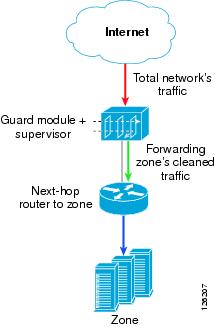
You can install the Guard module in one of the following network configurations:
•
Figure 5-1 Inline Network Configuration
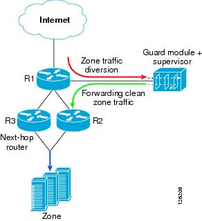
•
Figure 5-2 Out-of-Path Network Configuration
Understanding the Diversion Mechanism
The Guard module diversion configuration globally applies to all the zones that you define. The diversion configuration defines how packets are routed to each subnet and defines the routes needed for both hijacking and injection. When the Guard module is protecting a zone or when you activate the learning process, the Guard module uses the diversion configuration and the zone definition to determine how to divert traffic intended for that zone and how to inject traffic back to the zone main traffic path.
The Guard module uses an internal protocol, Route Health Injection (RHI), with the supervisor engine to add routes to the supervisor engine onboard routing table. The Guard module adds routes when the Guard module is protecting a zone or when you activate the learning process for a zone. The Guard module removes the routes when zone protection and the learning process end.
Note
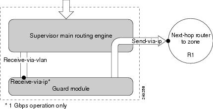
Figure 5-3 shows how packets are routed between the supervisor engine onboard routing engine and the Guard module.
Figure 5-3 Diversion Process
Note
This section contains the following topics:
•
•
•
•
Configuring Hijacking Parameters
Once zone protection is activated, the supervisor engine onboard routing engine hijacks the zone traffic to the Guard module. The traffic from the supervisor engine to the Guard module is hijacked on the receive-via-vlan VLAN. You can configure the same VLAN for hijacking and injecting traffic.
The Guard module installs a static route in the supervisor engine onboard routing table that points to the Guard module as the next hop to the zone. The static route ensures that the zone traffic is hijacked to the Guard module. The Guard module exploits the longest-prefix match algorithm; it divides each route into two routes with a longer prefix and advertises these routes to the supervisor engine onboard routing table. For example, the route for a 24-bit length zone subnet (class C) is published as two routes of 25-bit length zone subnets.
You can configure multiple hijacking routes. Each hijacking route has a weight that defines the route preference. The supervisor engine onboard routing engine prefers the path with the highest weight. By default, all hijacking routes are added with a weight of 1. You can change the default weight to define the preference among multiple hijacking routes.
You can associate specific hijacking parameters with an injection route. Alternatively, you can configure global hijacking parameters that apply to all injection routes.
Note
For information about how to associate hijacking parameters with an injection route, see the "Configuring Traffic Injection Parameters" section.
(1-Gbps operation only) To configure the global hijacking parameters, use the following command:
diversion hijacking {receive-via-ip receive-via-ip | receive-via-vlan [receive-via-vlan | native] | weight weight}
(3-Gbps operation only) To configure the global hijacking parameters, use the following command:
diversion hijacking {native vlan vlan_name | receive-via-vlan receive-via-vlan | weight weight}
Table 5-2 provides the arguments and keywords for the diversion hijacking command.
Configuring Traffic Injection Parameters
The Guard module removes malicious packets from the hijacked stream and returns the legitimate traffic either to the supervisor engine onboard routing engine (Layer 3) or directly to the zone main traffic path (Layer 2). The Guard module sends the legitimate traffic on send-via-vlan VLAN. The next-hop router and the Guard module must be on the same VLAN for Layer 2 injection. To inject traffic to the zone main traffic path in Layer 2, configure the next hop to the zone as the next-hop router IP address.
Caution
To configure traffic injection parameters, use the following command:
diversion injection ip-address ip-mask nexthop next-hop
Table 5-3 provides the arguments and keywords for the diversion injection command.
The IP address and subnet mask do not have to match the IP address and subnet mask of a specific zone. They can be a subset of the zone definition, or they can consist of subnets that include several zones. For example, you can use one or two commands to configure traffic diversion for a network that has hundreds of potential zones.
Associating Hijacking Parameters with an Injection Route
You can associate specific hijacking parameters with an injection route. Alternatively, you can configure global hijacking parameters that apply to all injection routes.
(1-Gbps operation only) To associate hijacking parameters with an injection route, use the following command:
diversion injection ip-address ip-mask nexthop next-hop [hijacking {receive-via-ip receive-via-ip | receive-via-vlan receive-via-vlan | weight weight}]
Table 5-4 provides the arguments and keywords for the diversion injection hijacking command.
(3-Gbps operation only) To associate hijacking parameters with an injection route, use the following command:
diversion injection ip-address ip-mask nexthop next-hop [hijacking {receive-via-vlan receive-via-vlan | weight weight}]
Table 5-5 provides the arguments and keywords for the diversion injection hijacking command.
Displaying the Diversion Routes
The Guard module modifies the supervisor engine onboard routing table using RHI messages. The Guard module adds routes when you enable zone protection or when you activate the learning process for a zone and removes the routes when zone protection and the learning process end.
To display the diversion settings on the Guard module, use the show diversion command.
You can display the RHI messages that the Guard module advertised on the supervisor engine when the Guard module is protecting a zone or learning the zone traffic characteristics only.
To display the routes that the Guard module advertised, use the following command on the supervisor engine:
show anomaly-guard module module_number advertised-route
The module_number argument specifies the number of the slot in which the module is installed.
The following 3-Gbps operation example shows how to display on the supervisor engine the routes that the Guard module advertised and displays an example route:
Sup# show anomaly-guard module 9 advertised-routeRHI routes added by slot 9ip mask nexthop vlan weight-------------- -------------- --------------- ------ ------A 192.168.252.8 255.255.255.0 192.168.8.10 8 1A 192.168.252.8 255.255.255.0 192.168.8.12 8 1A 192.168.252.8 255.255.255.0 192.168.8.14 8 1A 192.168.252.10 255.255.255.0 192.168.8.10 8 1A 192.168.252.10 255.255.255.0 192.168.8.12 8 1A 192.168.252.10 255.255.255.0 192.168.8.14 8 1To verify that the Guard module added the static routes, display the supervisor engine onboard routing table by entering the following command on the supervisor engine:
show ip route
The following example 3-Gbps operation shows how to display the static routes that the Guard module added to the supervisor engine onboard routing table. The static routes are marked with an "S."
Sup# show ip route 192.168.252.8Routing entry for 192.168.252.8/24, 3 known subnetsVariably subnetted with 2 masksS 192.168.252.10/32 [1/0] via 192.168.8.10, Vlan8[1/0] via 192.168.8.12, Vlan8[1/0] via 192.168.8.14, Vlan8S 192.168.252.8/32 [1/0] via 192.168.8.10, Vlan8[1/0] via 192.168.8.12, Vlan8[1/0] via 192.168.8.14, Vlan8Configuring the Guard Module in an Inline Network Configuration
In an inline network configuration, the Guard module is installed in a switch or router that resides on the zone critical path (the zone traffic flows through the switch or router whether or not the Guard module is protecting the zone).
This section contains the following topics:
•
•
•
Configuring Traffic Hijacking
To configure traffic diversion, the Guard module adds routes to the supervisor engine onboard routing table using RHI messages with the longest-prefix match. See the "Configuring Hijacking Parameters" section for more information.
Configuring Traffic Injection
To return the legitimate traffic to its original data path, configure Layer 2 or Layer 3 traffic injection. See the "Understanding Traffic Injection Methods" section for more information.
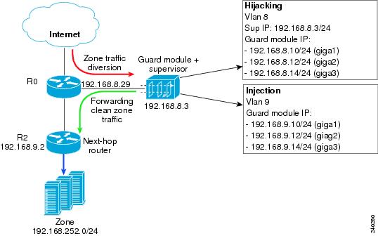
Inline Network Configuration Example
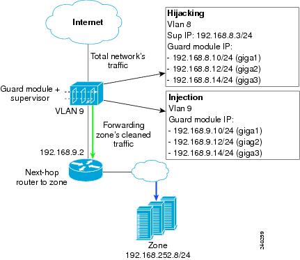
Figure 5-4 displays an example of traffic diversion in an inline network configuration. The following example is based upon the following conditions:
•
•
•
Note
Figure 5-4 Sample Inline Network Configuration with a Layer 3 Topology (3-Gbps operation)
•
•
To configure the supervisor engine and the Guard module as shown in the 3-Gbps operation sample configuration of Figure 5-4, perform the following steps:
Step 1
Sup# conf termSup(config)# vlan 8,9Sup(config)# anomaly-guard module 9 port 1 allowed-vlan 8,9Sup(config)# anomaly-guard module 9 port 2 allowed-vlan 8,9Sup(config)# anomaly-guard module 9 port 3 allowed-vlan 8,9Sup(config)# interface vlan 8Sup(config-if)# ip address 192.168.8.3 255.255.255.0Sup(config-if)# no ip proxy-arpSup(config-if)# no shutdownSup(config-if)# exitSup(config)# interface vlan 9Sup(config-if)# ip address 192.168.9.3 255.255.255.0Sup(config-if)# no ip proxy-arpSup(config-if)# no shutdownSup(config-if)# exitSup(config)# interface GigabitEthernet2/2Sup(config-if)# switchportSup(config-if)# switchport mode accessSup(config-if)# switchport access vlan 9Step 2
user@GUARD# conf termuser@GUARD-conf# interface giga 1.8user@GUARD-conf-if-giga1.8# ip address 192.168.8.10 255.255.255.0user@GUARD-conf-if-giga1.8# no shutdownuser@GUARD-conf-if-giga1.8# interface giga 1.9user@GUARD-conf-if-giga1.9# ip address 192.168.9.10 255.255.255.0user@GUARD-conf-if-giga1.9# no shutdownuser@GUARD-conf-if-giga1.9# interface giga 2.8user@GUARD-conf-if-giga2.8# ip address 192.168.8.12 255.255.255.0user@GUARD-conf-if-giga2.8# no shutdownuser@GUARD-conf-if-giga2.8# interface giga 2.9user@GUARD-conf-if-giga2.9# ip address 192.168.9.12 255.255.255.0user@GUARD-conf-if-giga2.9# no shutdownuser@GUARD-conf-if-giga2.9# interface giga 3.8user@GUARD-conf-if-giga3.8# ip address 192.168.8.14 255.255.255.0user@GUARD-conf-if-giga3.8# no shutdownuser@GUARD-conf-if-giga3.8# interface giga 3.9user@GUARD-conf-if-giga3.9# ip address 192.168.9.14 255.255.255.0user@GUARD-conf-if-giga3.9# no shutdownuser@GUARD-conf-if-giga3.9# exitStep 3
user@GUARD# conf termuser@GUARD-conf# diversion hijacking receive-via-vlan 8user@GUARD-conf# diversion injection 192.168.252.0 255.255.255.0 nexthop 192.168.9.2Step 4
See the "Synchronizing a Guard Module with a Detector Zone Configuration" section on page 6-8 and Chapter 10, "Protecting Zones," for more information.
Step 5
The following example shows how to display the routes that the Guard module advertised to the supervisor engine:
Sup# show anomaly-guard module 9 advertised-routeRHI routes added by slot 9ip mask nexthop vlan weight-------------- -------------- --------------- ------ ------A 192.168.252.0 255.255.255.128 192.168.8.10 8 1A 192.168.252.0 255.255.255.128 192.168.8.12 8 1A 192.168.252.0 255.255.255.128 192.168.8.14 8 1A 192.168.252.128 255.255.255.128 192.168.9.10 8 1A 192.168.252.128 255.255.255.128 192.168.9.12 8 1A 192.168.252.128 255.255.255.128 192.168.9.14 8 1
Note
Step 6
The following example shows how to display the static routes that were added to the supervisor engine onboard routing table:
Sup# show ip route 192.168.252.0Routing entry for 192.168.252.0/24, 3 known subnetsVariably subnetted with 2 masksS 192.168.252.128/25 [1/0] via 192.168.8.10, Vlan8[1/0] via 192.168.8.12, Vlan8[1/0] via 192.168.8.14, Vlan8S 192.168.252.0/25 [1/0] via 192.168.8.10, Vlan8[1/0] via 192.168.8.12, Vlan8[1/0] via 192.168.8.14, Vlan8
Configuring the Guard Module in an Out-of-Path Network Configuration
In out-of-path network configuration, the Guard module is installed in a switch or router that does not stand in the regular line of zone traffic but outside the regular line of zone traffic. The zone traffic is diverted from the regular line of zone traffic to the switch or router.
This section contains the following topics:
•
•
•
Configuring Traffic Hijacking
To configure traffic diversion, the Guard module adds static routes to the supervisor engine onboard routing table using RHI messages with the longest-prefix match to ensure that the zone traffic is forwarded directly to the Guard module. See the "Configuring Hijacking Parameters" section for more information.
When the Guard module is protecting a zone or when you activate the learning process, the Guard module modifies the supervisor engine onboard routing table. You must configure the supervisor engine or the Multilayer Switch Feature Card (MSFC) to issue a border gateway protocol (BGP) announcement to the router from which the zone traffic is hijacked (divert-from-router). The BGP announcement can be an interior BGP (iBGP) or exterior BGP (eBGP) announcement. The divert-from-router modifies its routing table based on the BGP announcement that the supervisor engine advertises. The announcement lists the Guard as the best next hop to the specific zone. To ensure that the router that forwards the traffic from the Guard module on to the zone does not forward the BGP announcement, set the no-advertise and no-export BGP community strings. Setting the no-advertise and no-export BGP community strings ensures that when packets destined to the zone reach the next-hop router, the router forwards the packet to the zone and not back to the Guard module.
Configuring Traffic Injection
To return the legitimate traffic to its original data path, configure Layer 2 or Layer 3 traffic injection. See the "Understanding Traffic Injection Methods" section for more information.
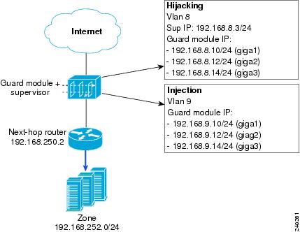
Out-of-Path Network Configuration Example
Figure 5-5 displays an example of traffic diversion in an out-of-path network configuration. In this example, hijacking is performed in Layer 3 and injection is performed in Layer 2.
Note
Figure 5-5 Sample Out-of-Path Network Configuration with a Layer-3 Topology (3-Gbps operation)
•
•
•
Note
To configure the supervisor engine and the Guard module as shown in the 3-Gbps operation sample configuration of Figure 5-5, perform the following steps:
Step 1
sup# conf termSup(config)# vlan 8,9Sup(config)# anomaly-guard module 9 port 1 allowed-vlan 8,9Sup(config)# anomaly-guard module 9 port 2 allowed-vlan 8,9Sup(config)# anomaly-guard module 9 port 3 allowed-vlan 8,9Sup(config)# interface vlan 8Sup(config-if)# ip address 192.168.8.3 255.255.255.0Sup(config-if)# no ip proxy-arpSup(config-if)# no shutdownSup(config-if)# exitSup(config)# interface vlan 9Sup(config-if)# ip address 192.168.9.3 255.255.255.0Sup(config-if)# no ip proxy-arpSup(config-if)# no shutdownSup(config-if)# exitSup(config)# interface GigabitEthernet2/2Sup(config-if)# switchport mode trunkSup(config-if)# switchport trunk encapsulation dot1qSup(config-if)# switchportSup(config-if)# switchport trunk allowed vlan 8,9Step 2
sup# conf termSup(config)# access-list 61 permit 192.168.8.10Sup(config)# access-list 61 permit 192.168.8.12Sup(config)# access-list 61 permit 192.168.8.14Sup(config)# route-map PERMIT_GUARD_ONLY permit 10Sup(config-route-map)# match ip next-hop 61Sup(config-route-map)# set community no-export no-advertiseSup(config-route-map)# exitSup(config)# route-map PERMIT_GUARD_ONLY deny 20Sup(config)# route-map STA2BGP permit 10Sup(config-route-map)# match ip next-hop 61Sup(config-route-map)# exitSup(config)# route-map STABGP deny 20Step 3
sup# conf termSup(config)# router bgp 55Sup(config-router)# bgp log-neighbor-changesSup(config-router)# neighbor 192.168.8.29 remote-as 100Sup(config-router)# address-family ipv4Sup(config-router-af)# redistribute static route-map STA2BGPSup(config-router-af)# neighbor 192.168.8.29 route-map PERMIT_GUARD_ONLY outSup(config-router-af)# neighbor 192.168.8.29 activateSup(config-router-af)# no auto-summarySup(config-router-af)# no synchronizationSup(config-router-af)# exit-address-familyStep 4
user@GUARD# conf termuser@GUARD-conf# interface giga 1.8user@GUARD-conf-if-giga1.8# ip address 192.168.8.10 255.255.255.0user@GUARD-conf-if-giga1.8# no shutdownuser@GUARD-conf-if-giga1.8# interface giga 2.8user@GUARD-conf-if-giga2.8# ip address 192.168.8.12 255.255.255.0user@GUARD-conf-if-giga2.8# no shutdownuser@GUARD-conf-if-giga2.8# interface giga 3.8user@GUARD-conf-if-giga3.8# ip address 192.168.8.14 255.255.255.0user@GUARD-conf-if-giga3.8# no shutdownuser@GUARD-conf-if-giga3.8# interface giga 1.9user@GUARD-conf-if-giga1.9# ip address 192.168.9.10 255.255.255.0user@GUARD-conf-if-giga1.9# no shutdownuser@GUARD-conf-if-giga1.9# interface giga 2.9user@GUARD-conf-if-giga2.9# ip address 192.168.9.12 255.255.255.0user@GUARD-conf-if-giga2.9# no shutdownuser@GUARD-conf-if-giga2.9# interface giga 3.9user@GUARD-conf-if-giga3.9# ip address 192.168.9.14 255.255.255.0user@GUARD-conf-if-giga3.9# no shutdownuser@GUARD-conf-if-giga3.9# exitStep 5
user@GUARD# conf termuser@GUARD-conf# diversion hijacking receive-via-vlan 8user@GUARD-conf# diversion injection 192.168.252.0 255.255.255.0 nexthop 192.168.9.2Step 6
RouterR0# conf termRouterR0(config)# router bgp 100RouterR0(config-router)# neighbor 192.168.8.3 remote-as 55Step 7
See the "Synchronizing a Guard Module with a Detector Zone Configuration" section on page 6-8 and Chapter 10, "Protecting Zones," for more information.
Step 8
The following example shows how to display the routes that the Guard module advertised to the supervisor engine:
Sup# show anomaly-guard module 9 advertised-routeRHI routes added by slot 9ip mask nexthop vlan weight-------------- -------------- --------------- ------ ------ A 192.168.252.8 255.255.255.0 192.168.8.10 8 1A 192.168.252.8 255.255.255.0 192.168.8.12 8 1A 192.168.252.8 255.255.255.0 192.168.8.14 8 1
Note
Step 9
The following example shows how to display the static routes that were added to the supervisor engine onboard routing table:
Sup# show ip route...192.168.252.0/24 is variably subnetted, 3 subnets, 2 masksS 192.168.252.0/25 [1/0] via 192.168.8.10, Vlan8[1/0] via 192.168.8.12, Vlan8[1/0] via 192.168.8.14, Vlan8S 192.168.252.128/25 [1/0] via 192.168.8.10, Vlan8[1/0] via 192.168.8.12, Vlan8[1/0] via 192.168.8.14, Vlan8Step 10
The following example shows the BGP routing table before the Guard module advertised the new routes to the zone:
RouterR0# show ip bgp...Network Next Hop Metric LocPrf Weight Path*> 192.168.252.0/24 192.168.9.2 0 0 100 ?The following example shows the BGP routing table after the Guard module advertised the new routes to the zone:
RouterR0# show ip bgp...Network Next Hop Metric LocPrf Weight Path*> 192.168.252.0/25 192.168.8.3 0 0 55 ?*> 192.168.252.128/25 192.168.8.3 0 0 55 ?RouterR0#
Understanding Traffic Injection Methods
This section describes different methods used for injecting the legitimate traffic from the Guard module to the next-hop router. The methods vary according to two main network topologies:
Layer 2 Topology
In a Layer 2 topology, the Guard module forwards the legitimate traffic directly to the next-hop router to return the legitimate traffic to its original destination. It does not require the supervisor engine to make a routing decision.
The Guard module locates the next-hop router MAC address by sending an Address Resolution Protocol (ARP) query to its IP address (see the "Configuring Traffic Injection Parameters" section for more information). It forwards the legitimate traffic to the switch or router interface that is connected to the relevant next-hop router. The supervisor engine and the next-hop router to the zone must be located on the same VLAN, and the Guard module must have an IP address on that VLAN.
See the "Inline Network Configuration Example" section and the "Out-of-Path Network Configuration Example" section for a configuration example.
Layer 3 Topology
In a Layer 3 topology, the supervisor engine must make a routing decision to inject the legitimate traffic back to its original destination. The Guard module can inject the legitimate traffic to one of the following destinations:
•
•
When activating a zone by entering the protect or the learning commands, the Guard module modifies the routing table (the supervisor engine onboard routing table or the routing table of the adjacent router, depending on the network topology) to be listed as the best path to the zone. If the Guard module returns the legitimate traffic to where it hijacked the traffic from, the result could be a routing loop. To prevent a routing loop, you can associate routing rules with the legitimate traffic that the Guard module forwards to the zone and configure these routing rules to override the global routing table.
You can use a Virtual Private Network (VPN) Routing and Forwarding (VRF) instance to create an additional forwarding table in the supervisor engine onboard routing engine to forward traffic without using the supervisor engine onboard routing table and avoid routing loops. Use this forwarding table to define an alternative injection path to route packets that are sent from the Guard module to the zone. Include only information on how to forward traffic to the next-hop router to the zone.
You can forward the zone traffic directly to the next-hop router or inject it into a Generic Routing Encapsulation (GRE) or IP in IP (IPIP) tunnel.
Figure 5-6 displays an example of a Layer 3 injection configuration.
Figure 5-6 Sample of Layer 3 Injection Configuration (3-Gbps operation)
This section contains the following topics:
•
•
Configuring the Guard Module and Supervisor Engine for VRF Traffic Injection
VRF is a traffic injection method that is deployed in Layer 3 network topologies where the Guard module injects the legitimate traffic back to the same router from which the traffic was hijacked. VRF can be applied in both an inline network configuration and in an out-of-path network configuration.
VRF enables you to create a routing and forwarding table (called the VRF table) in addition to the global routing and forwarding tables. Configure this table to route traffic that is received on the interface with the Guard module.
Note
•
•
Note
To configure the supervisor engine and the Guard module as shown in the sample configuration of Figure 5-6, perform the following steps:
Step 1
Sup# conf termSup(config)# ip vrf Guard-vrfSup(config-vrf)# rd 100:1Step 2
•
•
See the "Injecting Traffic Directly" section and the "Injecting Traffic Over a Tunnel" section for more information.
Step 3
Sup# conf termSup(config)# interface vlan 8Sup(config-if)# ip address 192.168.8.3 255.255.255.0Sup(config-if)# no ip proxy-arpSup(config-if)# no ip directed-broadcastSup(config-if)# no shutdownSup(config-if)# exitSup(config)# interface vlan 9Sup(config-if)# ip vrf forwarding Guard-vrfSup(config-if)# ip address 192.168.9.3 255.255.255.0Sup(config-if)# no ip proxy-arpSup(config-if)# no shutdownSup(config-if)# exitSup(config)# anomaly-guard module 9 port 1 allowed-vlan 8,9Sup(config)# anomaly-guard module 9 port 2 allowed-vlan 8,9Sup(config)# anomaly-guard module 9 port 3 allowed-vlan 8,9Step 4
user@GUARD# conf termuser@GUARD-conf# interface giga 1.8user@GUARD-conf-if-giga1.8# ip address 192.168.8.10 255.255.255.0user@GUARD-conf-if-giga1.8# no shutdownuser@GUARD-conf-if-giga1.8# interface giga 2.8user@GUARD-conf-if-giga2.8# ip address 192.168.8.12 255.255.255.0user@GUARD-conf-if-giga2.8# no shutdownuser@GUARD-conf-if-giga2.8# interface giga 3.8user@GUARD-conf-if-giga3.8# ip address 192.168.8.14 255.255.255.0user@GUARD-conf-if-giga3.8# no shutdownuser@GUARD-conf-if-giga3.8# interface giga 1.9user@GUARD-conf-if-giga1.9# ip address 192.168.9.10 255.255.255.0user@GUARD-conf-if-giga1.9# no shutdownuser@GUARD-conf-if-giga1.9# interface giga 2.9user@GUARD-conf-if-giga2.9# ip address 192.168.9.12 255.255.255.0user@GUARD-conf-if-giga2.9# no shutdownuser@GUARD-conf-if-giga2.9# interface giga 3.9user@GUARD-conf-if-giga3.9# ip address 192.168.9.14 255.255.255.0user@GUARD-conf-if-giga3.9# no shutdownuser@GUARD-conf-if-giga3.9# exitStep 5
user@GUARD# conf termuser@GUARD-conf# diversion hijacking receive-via-vlan 8user@GUARD-conf# diversion injection 192.168.252.0 255.255.255.0 nexthop 192.168.9.3Step 6
•
•
Injecting Traffic Directly
You can inject traffic directly to the zone by adding a static route to the VRF table to specify the route to the zone by entering the following command on the supervisor engine:
Sup(config)# ip route vrf Guard-vrf 192.168.252.0 255.255.255.0 192.168.250.2 globalThe global keyword indicates that the route to the next-hop router is learned from the global routing table.
Alternatively, you can define a specific routing protocol instance for each VRF. For example, you can use the address-family ipv4 vrf command to create a specific BGP instance for the VRF.
Injecting Traffic Over a Tunnel
To configure traffic injection over a tunnel, perform the following steps:
Step 1
Note
Sup# conf termSup(config)# interface tunnel5Sup(config-if)# ip address 192.168.145.2 255.255.255.252Sup(config-if)# tunnel source 192.168.8.3Sup(config-if)# tunnel destination 192.168.7.1Step 2
Router# conf termRouter(config)# interface tunnel5Router(config-if)# ip address 192.168.145.1 255.255.255.252Router(config-if)# tunnel source 192.168.7.1Router(config-if)# tunnel destination 192.168.8.3Step 3
Sup(config)# ip route vrf Guard-vrf 192.168.252.0 255.255.255.0 192.168.145.1 globalThe global keyword indicates that the route to the next-hop router is learned from the global routing table.
Validating the Guard Module Network Configuration
For 3-Gbps operation only, the Guard module validates the network configuration to verify that you have the three interface ports properly configured and activated. During the validation process, the Guard module checks the following network configuration parameters:
•
–
–
For information about configuring a VLAN, see the "Configuring a VLAN on the Guard Module Interfaces" section on page 3-9.
•
–
–
For information about configuring the physical interfaces, see the "Configuring a Physical Interface" section on page 3-8.
•
For information about defining a proxy address, see the "Configuring the Proxy IP Address" section on page 3-12.
•
For information about configuring a static route, see the (see the "Configuring Traffic Injection" section.
The Guard module automatically validates the network configuration whenever you activate zone protection or the learning process. You can also manually request the Guard module to validate the network configuration.
This section contains the following topics:
•
•
Validating the Network Configuration Manually
You can manually request the Guard to validate the network configuration by using the validate network-config command in either the global mode or the configuration mode.
The following example shows how to validate the network configuration in the configuration mode:
admin@rhTWJaffa-conf#validate network-config
Interfaces and vlans configuration is valid
Proxy configuration is valid
Setting the Automatic Validation Action
When you activate zone protection, the Guard module automatically validates the network configuration. If it detects a configuration problem, the Guard module either issues a warning or it fails to activate zone protection. To configure the action the Guard module takes when a problem exists with the network configuration, use the following command in the configuration mode:
validate-action network-config {activation-fail | activation-warn}
Table 5-6 provides the arguments for the validate-action network-config command.