Cisco RF Gateway 10 DS-48 Line Card Hardware Installation Guide
Available Languages
Contents
- Cisco RF Gateway 10 DS-48 Line Card
- Overview
- Cisco RFGW-10 DS-48 Line Card Components
- Tools and Equipment
- Safety Information and Warnings
- Electrical Equipment Guidelines
- Preventing Electrostatic Discharge Damage
- Warning Definition
- Safety Instructions
- Unpacking the Line Card
- Installing and Connecting the Line Card
- Removing the Line Card
- Troubleshooting the Line Card Installation
- Verifying the Status of the Line Card
- Additional References
- Obtaining Documentation and Submitting a Service Request
Cisco RF Gateway 10 DS-48 Line Card
The Cisco RF Gateway 10 (RFGW-10) DS-48 line card is a QAM modulator and upconverter product designed to support DOCSIS downstream data traffic (DEPI D-MPT) and video applications (VoD, SDV, and broadcast video).
- Overview
- Cisco RFGW-10 DS-48 Line Card Components
- Tools and Equipment
- Safety Information and Warnings
- Safety Instructions
- Unpacking the Line Card
- Installing and Connecting the Line Card
- Removing the Line Card
- Troubleshooting the Line Card Installation
- Verifying the Status of the Line Card
- Additional References
- Obtaining Documentation and Submitting a Service Request
Overview
The Cisco RFGW-10 DS-48 card is similar to the traditional QAM solutions where the card receives encapsulated data, de-packetizes/re-formats the packets, maps them to the output QAM channel, and performs QAM modulation and frequency upconversion. From a high level, the DS-48 line card receives Video and DOCSIS data encapsulated over Ethernet and outputs analog QAM data to the subscriber devices (STB, DOCSIS modems).
As a DOCSIS engine, the Cisco RFGW-10 DS-48 line card supports DEPI D-MPT mode (future SW releases may support PSP mode). DEPI is based on the L2TPv3 protocol, which includes a data plane and a control plane. DEPI data plane traffic is terminated at the line card. The Cisco RFGW-10 Supervisor terminates DEPI control and communicates the control to each line card in the system via the chassis IPC infrastructure. DOCSIS timing information (10.24MHz synchronous DTI clock) is received by the line card from the system TCC cards.
As a video engine, the Cisco RFGW-10 DS-48 terminates video data path traffic forwarded from the Supervisor Engine (video control plane traffic is terminated and processed by the system Supervisor). The Cisco RFGW-10 DS-48 processing path classifies video packets, performs inter QAM processing, bitrate scheduling, program muxing/scheduling, PID remapping, PCR re-stamping, and CC re-stamping.
A critical feature for the Cisco RFGW-10 DS-48 line card is redundancy and high availability support. The line cards are designed to detect and react to a wide range of faults and failures and respond with sub-second failover to a dedicated protect card.
The Cisco RFGW-10 DS-48 line card is designed to support a wide range of line card health conditions and initiate failover events if considered catastrophic:
- QAM or upconverter hardware failure. The line card monitors both the digital and RF data integrity. The modules also provide a comprehensive alarm structure to the system CPU, which allows constant monitoring of the UPX
- Environmental alarms (temperature, voltage, frequency)
- Software kernel failures
- Software module failure
- DTI Clock or Timing failures (both internal and external)
- SFP failures
Cisco RFGW-10 DS-48 Line Card Components
The Cisco RFGW-10 DS-48 line card has 12 physical RF ports, which support up to four QAMs per port. The number of QAM outputs is configurable on a per port basis (meaning an individual port can support 1, 2, or 4 QAMs as well as muting of individual QAMs within a QAM group). In stacked QAM mode, the QAMs are stacked contiguously over a 24-MHz or 32-MHz band. The line card supports a downstream channel frequency range of 88 MHz to 870 MHz.
The front panel has two 1xGigabit Ethernet ports and a single DVB-ASI interface (covers all video output streams). The front panel connectors support both copper and fiber SFP modules. The front panel Gigabit Ethernet ports are not processed directly by the line card, these are independent of the line card and route directly to the Supervisor switch fabric. These ports do not become out of service if the line card crashes and a failover to the redundant card occurs.
The following connectors and LEDs are located on the front panel of the DS-48 line card:
- STATUS LED that indicates the operating state of the line card
- ALARM LED that indicates the general health of the line card
- TRAFFIC LED that indicates whether the card is a primary (working card) or a protect card
- LINK LED that indicates whether the link is operational
- DVB-ASI BNC Coax Interface
- Two SFP Gigabit uplink ports
Cisco RFGW-10 DS-48 Line Card LEDs
LED Color/Status Description STATUS
Green
Line card is powered correctly and has initialized correctly
Off
Line card is not initialized correctly, not booted up
ALARM
Blank
Normal operation
Yellow
Minor line card error
Red
Major line card error
TRAFFIC
Green
Line card is active and traffic is processed by the card
Blue
Slot [11:12]: Card is configured as backup card
Red
Slots[3:10]: Card has failed over to protect slot
LINK
Green
The Link is operational
Blank
The Link is not operational
Safety Information and Warnings
Electrical Equipment Guidelines
- Before beginning any procedures requiring access to the chassis interior, locate the emergency power-off switch for the room in which you are working.
- Disconnect all power and external cables before moving a chassis.
- Do not work alone when potentially hazardous conditions exist.
- Never assume that power has been disconnected from a circuit; always check.
- Do not perform any action that creates a potential hazard to people or makes the equipment unsafe.
- Carefully examine your work area for possible hazards such as moist floors, ungrounded power extension cables, and missing safety grounds.
Preventing Electrostatic Discharge Damage
Electrostatic discharge (ESD) damage, occurs when electronic cards or components are improperly handled and can result in complete or intermittent failures. All line cards consist of a printed circuit card that is fixed in a metal carrier. Electromagnetic interference (EMI) shielding and connectors are integral components of the carrier. Although the metal carrier helps to protect the cards from ESD, use an antistatic strap each time you handle the modules. Handle the carriers by the edges only; never touch the cards or connector pins.
Caution
Always tighten the captive installation screws on all system components when you are installing them. These screws prevent accidental removal of the module, provide proper grounding for the system, and help to ensure that the line card connectors are properly seated in the backplane. Captive screws should be torqued to 6-8 in-lbs to ensure proper grounding and mechanical support. Never use cordless or corded drills to tighten screws; power screwdrivers and hand tools are acceptable.Static electricity can harm delicate components inside your system. To prevent static damage, discharge static electricity from your body before you touch any of your system components. As you continue to work on your system, periodically touch an unpainted metal surface on the computer chassis.
Following guidelines can prevent ESD damage:
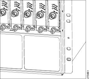
- Always use an ESD-preventive wrist or ankle strap and ensure that it makes good skin contact. Before removing a card from the chassis, connect the equipment end of the strap to the ESD plug at the bottom of the chassis below the power entry modules. Ensure that the chassis or rack or both have a grounding cable installed.
- Handle line cards by the faceplate and carrier edges only; avoid touching the card components or any connector pins.
- When removing a card, place the removed module component-side-up on an antistatic surface or in a static-shielding bag. If the module will be returned to the factory, immediately place it in a static-shielding bag.
- Avoid contact between the modules and clothing. The wrist-strap protects the card from ESD voltages on the body only; ESD voltages on clothing can still cause damage.
- When transporting a sensitive component, first place it an antistatic container or packaging.
- Handle all sensitive components in a static-safe area. If possible, use antistatic floor pads and workbench pads.
Caution
For safety, periodically check the resistance value of the antistatic strap. The measurement should be between 1 and 10 megohms.Warning Definition
Warning
IMPORTANT SAFETY INSTRUCTIONSThis warning symbol means danger. You are in a situation that could cause bodily injury. Before you work on any equipment, be aware of the hazards involved with electrical circuitry and be familiar with standard practices for preventing accidents. Use the statement number provided at the end of each warning to locate its translation in the translated safety warnings that accompanied this device. Statement 1071
SAVE THESE INSTRUCTIONS
Safety Instructions
Note
Do not unpack the module until you are ready to install it. Keep the module in the shipping container to prevent accidental damage until you determine an installation site. Use the appropriate unpacking documentation included with the module.
Warning
Read the installation instructions before connecting the system to the power source. Statement 1004
Warning
Only trained and qualified personnel should be allowed to install, replace, or service this equipment. Statement 1030
Warning
Ultimate disposal of this product should be handled according to all national laws and regulations. Statement 1040Unpacking the Line Card
SUMMARY STEPS
Caution
Make sure you are properly grounded with an electrostatic discharge damage (ESD)-preventative ground strap.
1. Remove the line card from the shipping container.
2. Place the card on an antistatic surface or leave the line card in its anti-static bag.
3. Review the installation information for the card.
DETAILED STEPS
Installing and Connecting the Line Card
SUMMARY STEPSThe Cisco RFGW-10 UEQAM has vertical chassis slots numbered from left to right.
Caution
During this procedure, wear grounding wrist-straps to avoid ESD damage to the card. Do not directly touch the backplane with your hand or any metal tool. This could result in an electric shock.
Caution
To prevent ESD damage, handle the line card by the carrier edges only. Do not touch any of the RF connectors along the back of the card.
1. Take the necessary precautions to prevent ESD damage as described in the Preventing Electrostatic Discharge Damage section.
2. Ensure that you have enough clearance to accommodate any interface equipment that you will connect directly to the Supervisor card ports.
3. Using a #2 phillips or a flathead screwdriver, loosen the captive installation screws that secure the line card blank panel or the existing line card (whichever is present).
4. Remove the line card blank panel or the existing line card from the appropriate RF-capable slot. If a blank panel is installed, keep it for future use. If you are removing an existing line card, follow the instructions in the Removing the Line Card section.
5. To install the line card, turn the module sideways with the board facing right, grasp the line card front panel with one hand and place your other hand under the side edge of the board to support the line card.
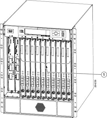
6. Align the edges of the line card carrier with the slot guides on the top and bottom of the Cisco RFGW-10 UEQAM chassis, as shown in Figure 3 .
7. Pivot the two module ejector levers out and away from the faceplate.
8. Carefully slide the line card into the appropriate slot until the notches on both the ejector levers engage the chassis top and bottom.
9. Using your thumb and forefinger of each hand to simultaneously pivot in both the ejector levers to fully seat the line card in the backplane connectors.
10. Use a # 2 Phillips screwdriver to tighten the captive installation screws on each end of the line card faceplate. Tighten the captive screws to 6-8 in-lbs.
DETAILED STEPS
Step 1 Take the necessary precautions to prevent ESD damage as described in the Preventing Electrostatic Discharge Damage section. Step 2 Ensure that you have enough clearance to accommodate any interface equipment that you will connect directly to the Supervisor card ports. Step 3 Using a #2 phillips or a flathead screwdriver, loosen the captive installation screws that secure the line card blank panel or the existing line card (whichever is present).
Note The line cards can be installed only in Slots 3 through 12. Step 4 Remove the line card blank panel or the existing line card from the appropriate RF-capable slot. If a blank panel is installed, keep it for future use. If you are removing an existing line card, follow the instructions in the Removing the Line Card section. Step 5 To install the line card, turn the module sideways with the board facing right, grasp the line card front panel with one hand and place your other hand under the side edge of the board to support the line card.
Caution Do not touch the printed circuit boards or the connector pins. Step 6 Align the edges of the line card carrier with the slot guides on the top and bottom of the Cisco RFGW-10 UEQAM chassis, as shown in Figure 3 . The line cards slide into the chassis guides on the sheet metal carrier edge.
Step 7 Pivot the two module ejector levers out and away from the faceplate. Step 8 Carefully slide the line card into the appropriate slot until the notches on both the ejector levers engage the chassis top and bottom. Step 9 Using your thumb and forefinger of each hand to simultaneously pivot in both the ejector levers to fully seat the line card in the backplane connectors.
Caution Always use the ejector levers when installing or removing a line card. A line card that is partially seated in the backplane will not function correctly.
Note The line card sheet metal carrier faceplate has holes on the top and bottom for aligning to the chassis pin features. This feature aids in positioning each line card faceplate within the chassis. Step 10 Use a # 2 Phillips screwdriver to tighten the captive installation screws on each end of the line card faceplate. Tighten the captive screws to 6-8 in-lbs.
Removing the Line Card
SUMMARY STEPS
Caution
When no fiber cable is connected, the aperture of the port may be emitting invisible radiation. Avoid exposure to the radiation and do not stare into the apertures.
Caution
During this procedure, wear grounding wrist-straps to avoid ESD damage to the card. Do not directly touch the backplane with your hand or any metal tool. This could result in an electric shock.
Caution
To prevent electrostatic discharge damage (ESD) damage, handle the line card by the carrier edges only.
1. Disconnect the network interface cables attached to the ports on the line card that you intend to remove.
2. Loosen the captive installation screws that secure the existing line card.
3. Grasp the top and bottom ejector levers and simultaneously pivot the levers outward to release the line card from the backplane connector.
4. Grasp the front panel of the line card with one hand and place your other hand under the side sheet metal carrier edge to support and guide it out of the slot. Do not touch the printed circuit board components or the connector pins.
5. Carefully pull the line card straight out of the slot keeping your other hand under the sheet metal carrier edge to guide it.
6. Place the line card on an antistatic mat or antistatic foam, or immediately install it in another slot.
7. If the slot is to remain empty, install a line card blank panel (part number RFGW-LC-COVER= ).
DETAILED STEPS
Troubleshooting the Line Card Installation
SUMMARY STEPS
1. Verify that the POWER LED is on (green). If the LED is off (not green):
2. Verify that the LEDs (see the line card LED table) illuminate and go through the power on self test (POST) when the line card is inserted in the chassis.
3. Verify that the captive screws and ejector levers are secure:
4. Verify that the card is properly seated in the chassis:
5. Verify that the SFP modules are properly seated in the ports on the faceplate:
DETAILED STEPS
Step 1 Verify that the POWER LED is on (green). If the LED is off (not green): Step 2 Verify that the LEDs (see the line card LED table) illuminate and go through the power on self test (POST) when the line card is inserted in the chassis. Step 3 Verify that the captive screws and ejector levers are secure: Step 4 Verify that the card is properly seated in the chassis: Step 5 Verify that the SFP modules are properly seated in the ports on the faceplate:
Verifying the Status of the Line Card
SUMMARY STEPS
1. Ensure that the STATUS LED illuminates green (module operational).
2. When the Cisco RFGW-10 DS-384 is online, use the show module command to verify that the system acknowledges the new module and that the status of the module status is good.
3. If the module is not operational, re-seat it. If the module is still not operational, contact your customer service representative.
DETAILED STEPS
Step 1 Ensure that the STATUS LED illuminates green (module operational). Step 2 When the Cisco RFGW-10 DS-384 is online, use the show module command to verify that the system acknowledges the new module and that the status of the module status is good. Step 3 If the module is not operational, re-seat it. If the module is still not operational, contact your customer service representative.
Additional References
Related Documents
Related Topic Document Title Bundle Image Upgrade—allows efficient upgrade of multiple devices simultaneously by programming them with a new image. Bundled Image Upgrade Alarm and Event Management—provides information about previous and current events in the system. Alarm and Event Management DOCSIS Timing Interface (DTI) Offset—enables DOCSIS timing offset adjustment. DTI Offset M-CMTS D-MPT Manual Mode—processes D-MPT traffic from the M-CMTS core. D-MPT M-CMTS DEPI M-CMTS DEPI Line Card Redundancy—supports two types of line card redundancy, 1:1 and 1:N 1:1 and 1:N Line Card Redundancy Cisco RFGW-10 commands Cisco RF Gateway 10 Command Reference Release Notes for Cisco RF Gateway 10 Release Notes MIBs
Technical Assistance
Description Link The Cisco Support website provides extensive online resources, including documentation and tools for troubleshooting and resolving technical issues with Cisco products and technologies.
To receive security and technical information about your products, you can subscribe to various services, such as the Product Alert Tool (accessed from Field Notices), the Cisco Technical Services Newsletter, and Really Simple Syndication (RSS) Feeds.
Access to most tools on the Cisco Support website requires a Cisco.com user ID and password.
Obtaining Documentation and Submitting a Service Request
For information on obtaining documentation, submitting a service request, and gathering additional information, see the monthly What's New in Cisco Product Documentation, which also lists all new and revised Cisco technical documentation, at:
http://www.cisco.com/en/US/docs/general/whatsnew/whatsnew.html
Subscribe to the What's New in Cisco Product Documentation as a Really Simple Syndication (RSS) feed and set content to be delivered directly to your desktop using a reader application. The RSS feeds are a free service and Cisco currently supports RSS version 2.0.


 Feedback