Feedback Feedback
|
Table Of Contents
Connector and Cable Specifications
Coaxial Connector and Cable Specifications
Ethernet Connector and Cabling
Console Port Connector and Cables
Connector and Cable Specifications
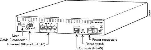
This appendix describes the pinouts and cabling requirements for the interfaces and cables used on the Cisco uBR905 router. All connectors for these interfaces are on the rear-panel, as shown in Figure B-1.
Figure B-1 Cisco uBR905 Cable Access Router Connectors
This appendix describes the following connectors and cabling requirements:
•
Coaxial Connector and Cable Specifications
•
•
Coaxial Connector and Cable Specifications
The Cisco uBR905 router connects to the HFC cable system with a type-F, right-angle, PCB-mount connector manufactured by Amp (model number 531-40047). The body is die cast out of zinc, with a tin-lead plating. The round, center contact is made of phosphor bronze, with a tin-lead plating. The insulator is polypropylene and will accept a coaxial cable center conductor with a diameter ranging from 0.022 inch (0.056 mm) to 0.042 inch (1.07 mm).
The coaxial cable used to connect the Cisco uBR7200 series universal broadband routers at the headend should be very high-quality cable because imperfections that do not visibly affect video transmissions can significantly affect digital data transmissions. In particular, poor insulation, improperly installed additional outlets, the condition and length of the cable's center conductor, and the quality of the cable can negatively affect the connectivity and performance of the cable access router for digital data transmission.
For example, a 5 dB reduction in signal quality for analog downstream video might cause a slight degradation of picture clarity, which might or might not be noticeable to a subscriber. However, a reduction of only 1 dB in signal quality for digital data might completely disrupt service to a Cisco uBR905 router user.
Cisco recommends that you use a headend-grade coaxial cable or a quad-shield coaxial cable with a minimum of 60% + 40% braid and double foil insulation to connect the cable modem cards to the HFC network. The center conductor must be straight and extend 1/8 inch (3.2 mm) beyond the end of the connector, and the connector should be securely crimped to the cable. The following cables are recommended:
•
•
•
Note
If you use different types of coaxial cable, the following problems can appear:
•
•
•
Note
Ethernet Connector and Cabling
The Cisco uBR905 router provides four RJ-45 connectors that provide the following Ethernet 10BaseT connectivity:
•
•
Figure B-2 shows the RJ-45 connector and plug used for the Cisco uBR905 router's Ethernet ports. Table B-1 lists the pinouts and signals for the RJ-45 connector.
Figure B-2 RJ-45 Connector and Plug
Table B-1 RJ-45 Receptacle Pinouts
1
Receive Data + (RxD+)
2
RxD-
3
Transmit Data + (TxD+)
6
TxD-
Note
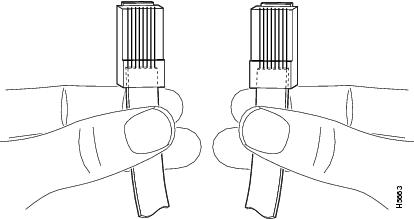
To identify the RJ-45 cable type, hold the two ends of the cable next to each other so you can see the colored wires inside the ends, as shown in Figure B-3.
Figure B-3 RJ-45 Cable Identification
Examine the sequence of colored wires to determine the type of RJ-45 cable:
•
•
Note
Console Port Connector and Cables
The Cisco uBR905 router provides an RJ-45 serial connector for asynchronous serial console access. The console port is a DCE device, so connecting it to another DTE device, such as the serial port on a laptop PC, requires a straight-through DCE-to-DTE cable.
Table B-2 lists the pinouts for the console port and for the cabling required when connecting to a DTE device that uses an RJ-45, DB-25, or DB-9 connector.
Table B-2 Console Port Signaling and Cabling
PinoutRTS
11
8
5
8
CTS
DTR
2
7
6
6
DSR
TxD
3
6
3
2
RxD
GND
4
5
7
5
GND
GND
5
4
7
5
GND
RxD
6
3
2
3
TxD
DSR
7
2
20
4
DTR
CTS
81
1
4
7
RTS
1 The console port does not support hardware flow control, so it does not support nor use the RTS and CTS signals. To accommodate other devices that use these signals, pin 1 on the console port (RTS) is connected internally to pin 8 (CTS), so that devices that assert the RTS signal automatically receive the CTS signal in reply.
The console port is hardwired for 9600 baud, 8 data bits, no parity, 1 stop bit (9600 8N1) and does not support either hardware or software flow control. If the console port is connected to a laptop computer or other PC when the Cisco uBR905 is first powered-on, the initial system banner should be displayed on the computer's console screen. If you do not see the system banner, verify that the laptop's serial port is set correctly and that it is properly connected to the console port.
Note