Cisco MDS 9000 Family NX-OS Interfaces Configuration Guide
Bias-Free Language
The documentation set for this product strives to use bias-free language. For the purposes of this documentation set, bias-free is defined as language that does not imply discrimination based on age, disability, gender, racial identity, ethnic identity, sexual orientation, socioeconomic status, and intersectionality. Exceptions may be present in the documentation due to language that is hardcoded in the user interfaces of the product software, language used based on RFP documentation, or language that is used by a referenced third-party product. Learn more about how Cisco is using Inclusive Language.
- Updated:
- July 9, 2014
Chapter: Configuring Interfaces
- Finding Feature Information
- Feature Information for Interfaces
- Prerequisites for Interfaces
- Guidelines and Limitations for Interfaces
- Default Settings for Interface Parameters
- Information About Interfaces
- Interface Description
- Interface Modes
- Interface States
- Graceful Shutdown
- 10-Gbps Fibre Channel Mode
- Port Administrative Speeds
- Frame Encapsulation
- Debounce Timer
- Bit Error Rate Threshold
- SFP Transmitter Types
- Port Guard
- Port Monitor
- Port Group Monitor
- Local Switching
- Slow-Drain Device Detection and Congestion Avoidance
- Interface Types
- Configuring a Fibre Channel Interface
- Setting the Interface Administrative State
- Configuring an Interface Mode
- Configuring the MAX NPIV Limit
- Configuring the System Default F Port Mode
- Configuring ISL Between Two Switches
- Configuring the 10-Gbps Fibre Channel Mode via the CLI
- Configuring the 10-Gbps Fibre Channel Mode via the Device Manager
- Configuring the Port Administrative Speed
- Configuring the Interface Description
- Specifying a Port Owner
- Configuring Beacon Mode
- Configuring a Switch Port Attribute Default Value
- Configuring the Port Guard
- Configuring Port Monitor
- Configuring Port Group Monitor
- Configuring the Management Interface
- Creating a VSAN Interface
- Configuring Slow-Drain Device Detection and Congestion Avoidance
- Configuring the Congestion Frame Timeout Value for FCoE
- Configuring Pause Frame Timeout Value for FCoE
- Configuring the Congestion Drop Timeout Value for Fibre Channel
- Configuring the No-Credit Frame Timeout Value for Fibre Channel
- Configuring the Slow-Port Monitor Timeout Value for Fibre Channel
- Displaying Credit Loss Recovery Actions
- Configuring the Transmit Average Credit-Not-Available Duration Threshold and Action
- Displaying Interface Information
- Displaying the Port-Level Port Guard
- Displaying the Port Monitor Status and Policies
- Displaying Port Group Monitor Status and Policies
- Displaying the Management Interface Configuration
- Displaying VSAN Interface Information
- Displaying the Congestion Frame Timeout Value for FCoE
- Displaying the Pause Frame Timeout Value for FCoE
- Displaying the Congestion Drop Timeout Value for Fibre Channel
- Displaying the No-Credit Frame Timeout Value for Fibre Channel
- Displaying Slow-Port Monitor Events
Configuring Interfaces
This document provides information about configuring and verifying interfaces on Cisco MDS 9000 Series Multilayer switches.
Finding Feature Information
Chapter 1, “New and Changed Information” or the Feature Information table below.
Feature Information for Interfaces
Table 3-1 lists the new and changed features for Cisco MDS NX-OS Release 6.2(x).
Prerequisites for Interfaces
Before you begin configuring interfaces, ensure that the modules in the chassis are functioning as designed. To verify the status of a module, enter the show module command in user EXEC mode. For information about verifying the module status, refer to the Cisco MDS 9000 Series NX-OS Fundamentals Configuration Guide.
Guidelines and Limitations for Interfaces
When you activate a port-monitor policy using the port-monitor activate policyname command, a syslog is generated to display that the policy is activated successfully. However, when you disable the policy using the no port-monitor activate policyname command and enable the policy again, there is no syslog message displayed about the policy activation. Use the no logging rate-limit command in the configuration mode to ensure that all syslogs are logged.
The guidelines and limitations for interfaces configuration are listed in the following topics:
- Guidelines for Configuring Port Monitor Interval
- Guidelines for Local Switching
- Guidelines for 10-Gbps Fibre Channel Mode
- Guidelines for VSAN Interface Configuration
Guidelines for Configuring Port Monitor Interval

Note![]() The value of the check interval is common across counters and policies.
The value of the check interval is common across counters and policies.
- Check interval should be less than the poll interval.
- Check interval is applicable to all the active port monitor policies configured.
- Users should deactivate all the active port monitor policies before enabling, modifying, or disabling the check interval functionality.
- Check interval cannot be enabled when an active policy is configured.
- Software downgrade to a version that does not support the check interval functionality is restricted when the check interval functionality is enabled.
- We recommend that you do not have a port guard action set to the state-change counter when an interface state is changed from down state to up state.
- We recommend that you do not use the default policy when the check interval is configured.
Let us consider a scenario where the poll interval, rising threshold, and check interval are configured with the following values:
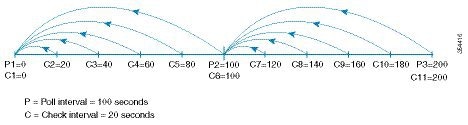
The check interval starts its interval, C1, along with the poll interval at P1. If an error occurs between the check intervals C2 and C3, the check intervals C2 and C3 are higher than the configured rising threshold value of 30, an alert (syslog or trap or both) is generated at C3, alerting the user that an error has occurred at that particular port.
Note![]() You can configure longer poll intervals to capture events across poll intervals. For example, configure a poll interval of 24 hours with a check interval of 30 seconds, with the rising threshold value being checked cumulatively every 30 seconds.
You can configure longer poll intervals to capture events across poll intervals. For example, configure a poll interval of 24 hours with a check interval of 30 seconds, with the rising threshold value being checked cumulatively every 30 seconds.
Guidelines for Local Switching
- All the ports should be in shared mode, which is usually the default state. To place a port in shared mode, enter the switchport rate-mode shared command.
- E ports are not allowed in the module because they must be in dedicated mode.
Note![]() Local switching is not supported on the Cisco MDS 9710 switch.
Local switching is not supported on the Cisco MDS 9710 switch.
Guidelines for 10-Gbps Fibre Channel Mode
- To change the port speed from 10 to 16 Gbps, use only the no 10g-speed-mode command. We do not recommend using the 16g-speed-mode command because the ports will move to unrecoverable state, and the only way to recover these ports is to issue the no 10g-speed-mode command.
- For Cisco MDS 9513, the ports in the module can be configured to 10-Gbps speed only when the DS-13SLT-FAB3 (fabric 3) module bandwidth is 256 Gbps. Any other combination of fabric modules or Cisco MDS 9506 or Cisco MDS 9509 will not let the ports come up in 10 Gbps.
- When the 8-Gbps modules are in 10-Gbps mode, the ports in the module that are not 10-Gbps capable are disabled and are in the out-of-service state. For DS-X9232-256K9, the ASIC range is eight ports, of which two ports will be out of service. For DS-X9248-256K9, the ASIC range is 12 ports, of which six ports will be out of service. For the 16-Gbps modules and fabric switch, all the ports have 10-G speed mode.
- The ports function only in full rate mode. They cannot be moved to shared rate mode.
- The ports cannot be configured in any other speed other than the speed values provided in the switchport speed command.
- Ports that are 10 Gbps capable and are disabled or are out of service cannot be put back in service using the no out-of-service command. To put these ports back in service, all the ports in the ASIC range need to be reconfigured with the no 10g-speed-mode command.
- Local switching must be disabled. Otherwise, ports cannot be configured in dedicated mode.
Thus, for interconnecting 16-Gbps Fibre Channel modules, 16 Gbps is the preferred speed. However, for interconnecting 8-Gbps modules, or for interconnecting 16-Gbps modules and 8-Gbps modules, we recommend 10 Gbps as the preferred speed.
Guidelines for VSAN Interface Configuration
- Create a VSAN before creating the interface for that VSAN. If a VSAN does not exist, the interface cannot be created.
- Create the interface VSAN; it is not created automatically.
- If you delete a VSAN, the attached interface is automatically deleted.
- Configure each interface only in one VSAN.

Tip![]() After configuring a VSAN interface, you can configure an IP address or the Virtual Router Redundancy Protocol (VRRP) feature. See the Cisco MDS 9000 Series NX-OS IP Services Configuration Guide.
After configuring a VSAN interface, you can configure an IP address or the Virtual Router Redundancy Protocol (VRRP) feature. See the Cisco MDS 9000 Series NX-OS IP Services Configuration Guide.
Default Settings for Interface Parameters
Table 3-2 lists the default settings for interface parameters.
|
|
|
|---|---|
On (unless changed during initial setup) in non-NPV and NPIV core switches. Off in NPV switches. |
|
Information About Interfaces
The main function of a switch is to relay frames from one data link to another. To relay frames, the characteristics of the interfaces through which the frames are received and sent must be defined. The configured interfaces can be Fibre Channel interfaces, Gigabit Ethernet interfaces, the management interface, or VSAN interfaces.
This section includes the following topics:
- Interface Description
- Interface Modes
- Interface States
- Graceful Shutdown
- 10-Gbps Fibre Channel Mode
- Port Administrative Speeds
- Frame Encapsulation
- Debounce Timer
- Bit Error Rate Threshold
- SFP Transmitter Types
- Port Guard
- Port Monitor
- Port Group Monitor
- Local Switching
- Slow-Drain Device Detection and Congestion Avoidance
- Interface Types
Interface Description
For Fibre Channel interfaces, you can configure the description parameter to provide a recognizable name for an interface. Using a unique name for each interface allows you to quickly identify an interface when you are looking at a listing of multiple interfaces. You can also use the description to identify the traffic or the use for a specific interface.
Interface Modes
Each physical Fibre Channel interface in a switch operates in one of the following port modes
(see Figure 3-1):
Note![]() Besides these modes, each interface can be configured in auto port mode or Fx port mode. These two modes determine the port type during interface initialization.
Besides these modes, each interface can be configured in auto port mode or Fx port mode. These two modes determine the port type during interface initialization.
Figure 3-1 Cisco MDS 9000 Series Switch Port Modes
Note![]() Interfaces are created in VSAN 1 by default. For information about VSANs, see the Cisco MDS 9000 Series NX-OS Fabric Configuration Guide.
Interfaces are created in VSAN 1 by default. For information about VSANs, see the Cisco MDS 9000 Series NX-OS Fabric Configuration Guide.
Each interface has an associated administrative configuration and an operational status:
- The administrative configuration does not change unless you modify it. This configuration has various attributes that you can configure in administrative mode.
- The operational status represents the current status of a specified attribute, such as the interface speed. This status cannot be changed and is read-only. Some values, for example, operational speed, may not be valid when the interface is down.
Note![]() When a module is removed and replaced with the same type of module, the original configuration is retained. If a different type of module is inserted, the original configuration is no longer retained.
When a module is removed and replaced with the same type of module, the original configuration is retained. If a different type of module is inserted, the original configuration is no longer retained.
E Port
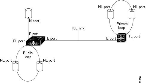
In expansion port (E port) mode, an interface functions as a fabric expansion port. This port can be connected to another E port to create an Inter-Switch Link (ISL) between two switches. E ports carry frames between switches for configuration and fabric management. They serve as a conduit between switches for frames destined for remote N ports and NL ports. E ports support Class 2, Class 3, and Class F services.
An E port connected to another switch can also be configured to form a port channel. For more details about configuring a port channel, see Chapter 6, “Configuring Port Channels”.
F Port
In fabric port (F port) mode, an interface functions as a fabric port. This port can be connected to a peripheral device (host or disk) operating as an N port. An F port can be attached to only 1 N port. F ports support Class 2 and Class 3 services.
FL Port
In fabric loop port (FL port) mode, an interface functions as a fabric loop port. This port can be connected to one or more NL ports (including FL ports in other switches) to form a public, arbitrated loop. If more than one FL port is detected on the arbitrated loop during initialization, only one FL port becomes operational and the other FL ports enter nonparticipating mode. FL ports support Class 2 and Class 3 services.
Note![]() FL port mode is not supported on 4-port 10 Gbps switching module interfaces.
FL port mode is not supported on 4-port 10 Gbps switching module interfaces.
NP Ports
An NP port is a port on a device that is in NPV mode and connected to the core switch via an F port. NP ports function like N ports, except that in addition to providing N port operations, they also function as proxies for multiple physical N ports.
For more details about NP ports and NPV, see Chapter7, “Configuring N Port Virtualization”
TE Port
In trunking E port (TE port) mode, an interface functions as a trunking expansion port. It can be connected to another TE port to create an extended ISL (EISL) between two switches. TE ports are specific to Cisco MDS 9000 Series Multilayer Switches. These switches expand the functionality of E ports to support the following:
In TE port mode, all the frames are transmitted in EISL frame format, which contains VSAN information. Interconnected switches use the VSAN ID to multiplex traffic from one or more VSANs across the same physical link. This feature is referred to as trunking in the Cisco MDS 9000 Series Multilayer Switches. For more details about trunking, see Chapter 5, “Configuring Trunking”. TE ports support Class 2, Class 3, and Class F services.
TF Port
In trunking F port (TF port) mode, an interface functions as a trunking expansion port. It can be connected to another trunked N port (TN port) or trunked NP port (TNP port) to create a link between a core switch and an NPV switch or a host bus adapter (HBA) in order to carry tagged frames. TF ports are specific to Cisco MDS 9000 Series Multilayer Switches. They expand the functionality of F ports to support VSAN trunking.
In TF port mode, all the frames are transmitted in EISL frame format, which contains VSAN information. Interconnected switches use the VSAN ID to multiplex traffic from one or more VSANs across the same physical link. This feature is referred to as trunking in the Cisco MDS 9000 Series Multilayer Switches. For more details about trunking, see Chapter 5, “Configuring Trunking”. TF ports support Class 2, Class 3, and Class F services.
TNP Port
In trunking NP port (TNP port) mode, an interface functions as a trunking expansion port. It can be connected to a trunked F port (TF port) to create a link to a core NPIV switch from an NPV switch in order to carry tagged frames.
SD Port
In SPAN destination port (SD port) mode, an interface functions as a switched port analyzer (SPAN). The SPAN feature is specific to switches in the Cisco MDS 9000 Series. It monitors network traffic that passes though a Fibre Channel interface. This is done using a standard Fibre Channel analyzer (or a similar switch probe) that is attached to an SD port. SD ports do not receive frames; they only transmit a copy of the source traffic. The SPAN feature is non-intrusive and does not affect switching of network traffic in SPAN source ports. For more details about SPAN, see the Cisco MDS 9000 Series NX-OS System Management Configuration Guide.
ST Port
In the SPAN tunnel port (ST port) mode, an interface functions as an entry point port in the source switch for the RSPAN Fibre Channel tunnel. The ST port mode and the remote SPAN (RSPAN) feature are specific to switches in the Cisco MDS 9000 Series Multilayer Switches. When configured in ST port mode, the interface cannot be attached to any device, and thus cannot be used for normal Fibre Channel traffic. For more details about SPAN, see the Cisco MDS 9000 Series NX-OS System Management Configuration Guide.
Note![]() ST port mode is not supported on the Cisco MDS 9124 Fabric Switch, the Cisco Fabric Switch for HP c-Class BladeSystem, and the Cisco Fabric Switch for IBM BladeCenter.
ST port mode is not supported on the Cisco MDS 9124 Fabric Switch, the Cisco Fabric Switch for HP c-Class BladeSystem, and the Cisco Fabric Switch for IBM BladeCenter.
Fx Port
Interfaces configured as Fx ports can operate in either F port mode or FL port mode. The Fx port mode is determined during interface initialization depending on the attached N port or NL port. This administrative configuration disallows interfaces to operate in any other mode, for example, preventing an interface to connect to another switch.
B Port
While E ports typically interconnect Fibre Channel switches, some SAN extender devices, such as the Cisco PA-FC-1G Fibre Channel port adapter, implement a bridge port (B port) model to connect geographically dispersed fabrics. This model uses B ports as described in the T11 Standard FC-BB-2.
If an FCIP peer is a SAN extender device that supports only Fibre Channel B ports, you should enable the B port mode for the FCIP link. When a B port mode is enabled, the E port functionality is also enabled and they coexist. Even if the B port mode is disabled, the E port functionality remains enabled. For more details about SPAN, see the Cisco MDS 9000 Series NX-OS IP Services Configuration Guide.
Auto Mode
Interfaces configured in auto mode can operate in F port, FL port, E port, TE port, or TF port mode. The port mode is determined during interface initialization. For example, if the interface is connected to a node (host or disk), it operates in F port mode or FL port mode depending on the N port mode or NL port mode. If the interface is attached to a third-party switch, it operates in E port mode. If the interface is attached to another switch in the Cisco MDS 9000 Series Multilayer Switches, it may become operational in TE port mode. For more details about trunking, see Chapter 5, “Configuring Trunking”.
TL ports and SD ports are not determined during initialization and are administratively configured.
Note![]() Fibre Channel interfaces on Storage Services Modules (SSMs) cannot be configured in auto mode.
Fibre Channel interfaces on Storage Services Modules (SSMs) cannot be configured in auto mode.
Interface States
An interface state depends on the administrative configuration of the interface and the dynamic state of the physical link.
Administrative States
Administrative state refers to the administrative configuration of an interface, as described in Table 3-3 .
|
|
|
|---|---|
Interface is disabled. If you administratively disable an interface by shutting down that interface, the physical link layer state change is ignored. |
Operational States
Operational state indicates the current operational state of an interface, as described in Table 3-4 .
Reason Codes
Reason codes are dependent on the operational state of an interface, as described in Table 3-5 .
|
|
|
|
|---|---|---|
Administratively down—If you administratively configure an interface as down, you disable the interface. No traffic is received or transmitted. |
||
See Table 3-6 . Only some of the reason codes are listed in Table 3-6 . |
If the administrative state is up and the operational state is down, the reason code differs based on the nonoperational reason code, as described in Table 3-6 .
Graceful Shutdown
Interfaces on a port are in a shut-down state by default (unless you modified the initial configuration).
The Cisco NX-OS software implicitly performs a graceful shutdown in response to either of the following actions for interfaces operating in E port mode:
- If you shut down an interface.
- If a Cisco NX-OS software application executes a port shutdown as part of its function.
A graceful shutdown ensures that no frames are lost when the interface is shutting down. When a shutdown is triggered either by you or the Cisco NX-OS software, the switches connected to the shutdown link coordinate with each other to ensure that all the frames in the ports are safely sent through the link before shutting down. This enhancement reduces the chance of frame loss.
A graceful shutdown is not possible in the following situations:
- If you physically remove the port from the switch.
- If In-Order Delivery (IOD) is enabled. For more details about IOD, see the Cisco MDS 9000 Series NX-OS Fabric Configuration Guide.
- If the Min_LS_interval is higher than 10 seconds. For information about Fabric Shortest Path First (FSPF) global configuration, see the Cisco MDS 9000 Series NX-OS Fabric Configuration Guide.
Note![]() This feature is triggered only if both the switches at either end of the E port interface are Cisco MDS switches and are running Cisco SAN-OS Release 2.0(1b) or later, or Cisco MDS NX-OS Release 4.1(1a) or later.
This feature is triggered only if both the switches at either end of the E port interface are Cisco MDS switches and are running Cisco SAN-OS Release 2.0(1b) or later, or Cisco MDS NX-OS Release 4.1(1a) or later.
10-Gbps Fibre Channel Mode
Some Cisco MDS Fibre Channel 8 and 16-Gbps modules and the Cisco MDS 9396S 16-Gbps Fabric Switch have the capability to run at 10-Gbps speed, and in two modes:
Benefits of 10-Gbps Fibre Channel Mode
A 10-Gbps Fibre Channel uses a more efficient encoding and a faster clock rate than an 8-Gbps Fibre Channel. Therefore, it has an approximately 50-percent throughput advantage over an 8-Gbps Fibre Channel. Consequently, fewer links are needed to achieve a given bandwidth.
Supported Modules and Switches
The following modules and switches support 10-Gbps mode:
- 32-port Cisco MDS 1/2/4/8/10-Gbps Advanced Fibre Channel Module (DS-X9232-256K9)
- 48-port Cisco MDS 1/2/4/8/10-Gbps Advanced Fibre Channel Module (DS-X9248-256K9)
- 48-port Cisco MDS 2/4/8/10/16-Gbps Advanced Fibre Channel Module (DS-X9448-768K9)
- 96-port Cisco MDS 9396S 2/4/8/10/16-Gbps Fabric Switch (DS-C9396S-96EK9)
Note![]() By default, all the above are in their native Fibre Channel speed (1/2/4/8 or 2/4/8/16 Gbps) mode.
By default, all the above are in their native Fibre Channel speed (1/2/4/8 or 2/4/8/16 Gbps) mode.
The following tables contain information about each module and the port ranges that need to be configured in 10-Gbps speed:
|
|
|
|
|---|---|---|
|
|
|
|
|---|---|---|
|
|
|
|---|---|
|
|
|
|---|---|
Port Administrative Speeds
By default, the port administrative speed for an interface is automatically calculated by the switch.
For internal ports on the Cisco Fabric Switch for HP c_Class BladeSystem and Cisco Fabric Switch for IBM BladeCenter, a port speed of 1 Gbps is not supported. Auto negotiation is supported between 2 and 4 Gbps only. Also, if the BladeCenter is a T chassis, then port speeds are fixed at 2 Gbps, and auto negotiation is not enabled.
Auto Sensing
Auto sensing speed is enabled on all 4 and 8-Gbps switching module interfaces by default. This configuration enables the interfaces to operate at speeds of 1, 2, or 4 Gbps on 4 Gbps switching modules, and 8 Gbps on 8-Gbps switching modules. When auto sensing is enabled for an interface operating in dedicated rate mode, 4 Gbps of bandwidth is reserved even if the port negotiates at an operating speed of 1 or 2 Gbps.
To avoid wasting unused bandwidth on 48-port and 24-port 4 and 8 Gbps Fibre Channel switching modules, you can specify that only 2 Gbps of required bandwidth be reserved, not the default of 4 or 8 Gbps. This feature shares the unused bandwidth within the port group, provided the bandwidth does not exceed the rate limit configuration for the port. You can also use this feature for shared rate ports that are configured for auto sensing.
Tip![]() When migrating a host that supports up to 2-Gbps traffic (that is, not 4 Gbps with auto-sensing capabilities) to the 4 Gbps switching modules, use auto sensing with a maximum bandwidth of 2 Gbps. When migrating a host that supports up to 4-Gbps traffic (that is, not 8 Gbps with auto-sensing capabilities) to the 8 Gbps switching modules, use auto sensing with a maximum bandwidth of 4 Gbps.
When migrating a host that supports up to 2-Gbps traffic (that is, not 4 Gbps with auto-sensing capabilities) to the 4 Gbps switching modules, use auto sensing with a maximum bandwidth of 2 Gbps. When migrating a host that supports up to 4-Gbps traffic (that is, not 8 Gbps with auto-sensing capabilities) to the 8 Gbps switching modules, use auto sensing with a maximum bandwidth of 4 Gbps.
Frame Encapsulation
The switchport encap eisl command applies only to SD port interfaces. This command determines the frame format for all the frames transmitted by the interface in SD port mode. If the encapsulation is set to EISL, all outgoing frames are transmitted in the EISL frame format, regardless of the SPAN sources. For information about encapsulation, see the Cisco MDS 9000 Series NX-OS System Management Configuration Guide.
The switchport encap eisl command is disabled by default. If you enable encapsulation, all outgoing frames are encapsulated, and you will see a new line (Encapsulation is eisl) in the show interface SD_port_interface command output. For information about encapsulation, see the Cisco MDS 9000 Series NX-OS System Management Configuration Guide.
Debounce Timer
Debounce timers delay the notification of link changes that can decrease traffic loss due to a network reconfiguration.
There are two types of debounce timers:
- Sync Loss: This timer applies when a link is active. A link is active after the link initialization (LRLRR-IDLE-IDLE) is successful. If there is synchronization loss for less than 100 ms when the Fibre Channel link is active, the interface does not bounce, but remains active. The value for debounce timer link down due to synchronization loss is 100 ms for Fibre Channel interfaces. This value cannot be configured. If there is synchronization loss for 100 ms or more when the Fibre Channel link is active, the interface goes down with the following message:
%PORT-5-IF_DOWN_LINK_FAILURE: %$VSANvsan%$ Interfaceintfis down (Link failure loss of sync) - NOS/OLS: This timer applies when a Fibre Channel port is initializing prior to when it is active. A Fibre Channel port is initializing prior to FLOGI or ACC (FLOGI) for F ports and ELP or ACC (ELP) for E ports. During the port initialization if a Fibre Channel interface encounters multiple NOS/OLS sequences continuously for a threshold of 10 times in 2 seconds, the interface is going to be moved to the errDisabled state with the following message:
%PORT-5-IF_DOWN_LINK_FAILURE: %$VSANvsan%$ Interfaceintfis down (Link failure due to NOS/OLS debounce timeout)The value for NOS/OLS debounce timer is 2 seconds and not configurable.
Bit Error Rate Threshold
The bit error rate (BER) threshold is used by a switch to detect an increased error rate before performance degradation seriously affects traffic.
Bit errors occur because of the following reasons:
- Faulty or bad cable
- Faulty or bad Gigabit Interface Converter (GBIC) or Small Form-Factor Pluggable (SFP)
- GBIC or SFP is specified to operate at 1 Gbps, but is used at 2 Gbps
- GBIC or SFP is specified to operate at 2 Gbps, but is used at 4 Gbps
- Short-haul cable is used for long haul or long-haul cable is used for short haul
- Momentary synchronization loss
- Loose cable connection at one end or both ends
- Improper GBIC or SFP connection at one end or both ends
A BER threshold is detected when 15 error bursts occur in a 5-minute period. By default, the switch disables the interface when the threshold is reached. Use the shutdown and no shutdown command sequence to re-enable the interface.
Disabling the Bit Error Rate Action
By default, the threshold disables the interface. However, you can configure the switch to not disable an interface when the threshold is crossed.
To disable the BER threshold for an interface, perform these steps:
Step 1![]() Enter configuration mode:
Enter configuration mode:
Step 2![]() Select a Fibre Channel interface and enter interface configuration submode:
Select a Fibre Channel interface and enter interface configuration submode:
Step 3![]() Prevent the detection of BER events from disabling the interface:
Prevent the detection of BER events from disabling the interface:
(Optional) Prevent the detection of BER events from enabling the interface:
Note![]() Regardless of the setting of the switchport ignore bit-errors command, a switch generates a syslog message when the BER threshold is exceeded.
Regardless of the setting of the switchport ignore bit-errors command, a switch generates a syslog message when the BER threshold is exceeded.
SFP Transmitter Types
The SFP hardware transmitters are identified by their acronyms when displayed using the show interface brief command. If the related SFP has a Cisco-assigned extended ID, the show interface and show interface brief commands display the ID instead of the transmitter type. The show interface transceiver and show interface fc slot / port transceiver commands display both values (ID and transmitter type) for Cisco-supported SFPs. Table 3-11 defines the acronyms used in the command output. For information about how to display interface information, see the Chapter 3, “Displaying Interface Information”.
|
|
|
|---|---|
|
|
|
|
|
|
Port Guard
The Port Guard feature is intended for use in environments where systems do not adapt quickly to a port going down and up (single or multiple times). For example, if a large fabric takes 5 seconds to stabilize after a port goes down, but the port actually goes up and down once per second, a severe failure might occur in the fabric, including devices becoming permanently unsynchronized.
The Port Guard feature provides the SAN administrator with the ability to prevent this issue from occurring. A port can be configured to stay down after a specified number of failures in a specified time period. This allows the SAN administrator to automate fabric stabilization, thereby avoiding problems caused by the up-down cycle.
Using the Port Guard feature, the SAN administrator can restrict the number of error events and bring a malfunctioning port to down state dynamically once the error events exceed the event threshold. A port can be configured such that it shuts down when specific failures occur.
There are two types of port guard, Port Level type and Port Monitor type. The former is a basic type where event thresholds are configurable on a per port basis, the latter allows the configuration of policies that are applied to all the ports of the same type, for example, all E ports or all F ports.
Note![]() We recommend against the simultaneous use of both types of port guard for a given port.
We recommend against the simultaneous use of both types of port guard for a given port.
Port-Level Port Guard
The following is the list of events that can be used to trigger port-level port guard actions:
- TrustSec violation — Link fails because of excessive TrsustSec violation events.
- Bit errors — Link fails because of excessive bit error events.
- Signal loss — Link fails because of excessive signal loss events.
- Signal synchronization loss — Link fails because of excessive signal synchronization events.
- Link reset — Link fails because of excessive link reset events.
- Link down — Link fails because of excessive link down events.
- Credit loss (Loop F ports only) — Link fails because of excessive credit loss events.
A link failure occurs when it receives two bad frames in an interval of 10 seconds and the respective interface will be error disabled. A general link failure caused by link down is the superset of all other causes. The sum of the number of all other causes equals the number of link-down failures. This means that a port is brought to down state when it reaches the maximum number of allowed link failures or the maximum number of specified causes.
Port-level Port Guard can be used to shut down misbehaving ports based on certain link event types. Event thresholds are configurable for each event type per port which makes them customizable between host, array, and tape F ports, or between intra- and inter-data center E ports, for example.
The events listed above might get triggered by certain events on a port, such as:
–![]() Receipt of Not Operational Signal (NOS)
Receipt of Not Operational Signal (NOS)
–![]() Too many hardware interrupts
Too many hardware interrupts
–![]() The detection of hardware faults
The detection of hardware faults
Port Monitor Port Guard
The Port Monitor Port Guard feature allows a port to be automatically error disabled or flapped when a given event threshold is reached.
Note![]() The Port Monitor Port Guard is not available for absolute counters.
The Port Monitor Port Guard is not available for absolute counters.
The following is the list of events that can be used to trigger the Port Monitor Port Guard actions:
- Port-to-forwarding engine frame error
- Crossbar-to-forwarding engine frame error
- Forwarding engine-to-crossbar frame error
- Credit loss
- Link loss
- Signal loss
- Signal synchronization loss
- Received data rate
- Received invalid CRC
- Received invalid words
- Received logical link resets
- Transmit credit not available
- Transmit data rate
- Transmit discards
- Transmit logical link resets
- Transmit slow port events
- Transmit wait
- Transit timeout discards
Port Monitor
The Port Monitor feature can be used to monitor the performance and status of ports and generate alerts when problems occur. You can configure thresholds for various counters and enable event triggers when the values cross the threshold.
For rising and falling thresholds, a syslog is generated only when the error count crosses these threshold values.
Table 3-12 displays the default port monitor policy with threshold values. The unit for threshold values (rising and falling) differs across different counters.
|
|
|
|
|
|
|
|
|
|
|---|---|---|---|---|---|---|---|---|
TX-Slowport-Count1 |
||||||||
TX-Slowport-Oper-Delay2 |
||||||||
TXWait3 |
||||||||
err-pkt-from-port_ASIC Error Pkt from Port4 |
||||||||
Note ●![]() TX-Slowport-Count is applicable only for 8-Gbps modules (DS-X9224-96K9, DS-X9248-96K9, and DS-X9248-48K9) in the Cisco MDS 9500 Series switches. In the default configuration, the port monitor sends an alert when a slow-port condition is detected 5 times in 1 second for the configured slow-port monitor timeout. (See the system timeout slowport-monitor command in the Cisco MDS 9000 Series Command Reference).
TX-Slowport-Count is applicable only for 8-Gbps modules (DS-X9224-96K9, DS-X9248-96K9, and DS-X9248-48K9) in the Cisco MDS 9500 Series switches. In the default configuration, the port monitor sends an alert when a slow-port condition is detected 5 times in 1 second for the configured slow-port monitor timeout. (See the system timeout slowport-monitor command in the Cisco MDS 9000 Series Command Reference).
- TX-Slowport-Oper-Delay is applicable only for advanced 8 and 16 Gbps modules. There are two defaults based on the module type:
–![]() For advanced 8-Gbps modules, the default rising threshold is 80 ms in a 1-second polling interval.
For advanced 8-Gbps modules, the default rising threshold is 80 ms in a 1-second polling interval.
–![]() For 16-Gbps modules, the default rising threshold is 50 ms in a 1-second polling interval.
For 16-Gbps modules, the default rising threshold is 50 ms in a 1-second polling interval.
- Configuring slow-port monitoring using the system timeout slowport-monitor command in order to get alerts for TX-Slowport-Count and TX-Slowport-Oper-Delay for a particular port type. (See the system timeout slowport-monitor command in the Cisco MDS 9000 Series Command Reference).
- Port guard action for TX-Slowport-Oper-Delay (for Absolute type counter) is not supported.
- TXWait is applicable only for advanced 8 and 16 Gbps modules. In the default configuration, the port monitor sends an alert if the transmit credit is not available for 400 ms (40%) in 1 second.
TXWait sends alerts when there are multiple slow-port events that have not hit the slow-port monitor threshold, but have together hit the TXWait threshold configured. For example, if there are 40 discrete 10-ms intervals of 0 TX credits in 1 second, TX-Slowport-Oper-Delay does not find these credits; TXWait finds the credits and sends an alert. - The state-change counter records the port down-to-port up action as one state change that is similar to flap. This is the reason the state-change counter does not have the port guard action set as flap.
- When the port guard action is set as flap, users get alerts only through syslog.
Three more counters were added in Cisco Release NX-OS 5.2(2a); these are not included in the default policy:
- err-pkt-from-port_ASIC Error Pkt from port
- err-pkt-to-xbar_ ASIC Error Pkt to xbar
- err-pkt-from-xbar_ ASIC Error Pkt from xbar
Table 3-13 displays the threshold value of the slow-drain port-monitor policy:
|
|
|
|
|
|
|
|
|
|---|---|---|---|---|---|---|---|
Note![]() If no other Port Monitor policy is explicitly activated, the slow-drain policy is activated. The default policy shows only the default counter-monitor values.
If no other Port Monitor policy is explicitly activated, the slow-drain policy is activated. The default policy shows only the default counter-monitor values.
Warning Threshold
From Cisco MDS NX-OS Release 6.2(15), the warning threshold functionality is available for each counter in a Port Monitor policy.
Port Monitor warning thresholds can be used to generate syslog messages before rising and falling thresholds are reached. A single threshold is configurable per Port Monitor counter. A syslog is generated whenever the counter crosses the configured warning threshold in either the rising or falling direction. This allows the user to track counters that are not severe enough to hit the rising threshold, but where nonzero events are of interest.
The warning threshold must be equal or less than the rising threshold and equal or greater than the falling threshold.
The warning threshold is optional; warning syslogs are only generated when it is specified in a counter configuration.
Check Interval
From Cisco MDS NX-OS Release 6.2(15), a new functionality called check interval is introduced to check errors at a shorter time interval than the poll interval.
Check interval polls for values more frequently within a poll interval so that the errors are detected much earlier and appropriate action can be taken.
With the existing poll interval, it is not possible to detect errors at an early stage. Users have to wait until the completion of the poll interval to detect the errors.
By default, the check interval functionality is not enabled.
Note ●![]() The port monitor check interval feature is supported only on the Cisco MDS 9710 Multilayer Director, Cisco MDS 9718 Multilayer Directors, and Cisco MDS 9706 Multilayer Directors.
The port monitor check interval feature is supported only on the Cisco MDS 9710 Multilayer Director, Cisco MDS 9718 Multilayer Directors, and Cisco MDS 9706 Multilayer Directors.
- Check interval is supported on both counters, absolute and delta.
- We recommend that you configure the poll interval as a multiple of the check interval.
- Check interval is supported on the Cisco MDS 9700 Series Multilayer Directors from Cisco MDS NX-OS Release 6.2(15) onwards, and on the Cisco MDS 9250i Multiservice Fabric Switch from Cisco MDS NX-OS Release 6.2(17) onwards.
- When a port comes up, the check interval will not provide an alert about invalid words for the port until the poll interval expires. We recommend that you bring up a set of ports at a given time in the module instead of all the ports.
Port Group Monitor
Note![]() Port Group Monitor functionality only applies to line cards that support oversubscription.
Port Group Monitor functionality only applies to line cards that support oversubscription.
The ports on a line card are divided into fixed groups called port groups that share a link of fixed bandwidth to the backplane. Since the total port bandwidth can exceed the backplane link bandwidth, frames will be queued, introducing traffic delays. The Port Group Monitor functionality can be used to monitor this oversubscription in both the transmit and receive directions to allow ports to be rebalanced between port groups before the delays become unacceptable.
When the Port Group Monitor feature is enabled and when a policy consisting of polling interval in seconds and the rising and falling thresholds in percentage are specified, the port group monitor generates a syslog if port group traffic goes above the specified percentage of the maximum supported bandwidth for that port group (for receive and for transmit). Another syslog is generated if the value falls below the specified threshold.
Table 3-14 shows the threshold values for the default Port Group Monitor policy:
|
|
|
|
|
|
|---|---|---|---|---|
Note![]() Port group monitor is not supported on a 1-rack box when any of the threshold values is reached for the receive performance and transmit performance counters.
Port group monitor is not supported on a 1-rack box when any of the threshold values is reached for the receive performance and transmit performance counters.
Local Switching
Local switching can be enabled in advanced 8-Gbps modules. This allows traffic to be switched directly with a local crossbar when the traffic is directed from one port to another on the same line card. By using local switching, an extra switching step is avoided, which in turn decreases the latency.
Slow-Drain Device Detection and Congestion Avoidance
Most SAN edge devices use Class 2 or Class 3 Fibre Channel services that have link-level flow control. This feature allows a receiving port to back pressure the sending peer port when the receiving port reaches its capacity to accept frames. When an edge device does not accept frames from the fabric for an extended time, it creates a condition in the fabric known as slow drain. If the upstream source of a slow-edge device is an ISL, it results in credit starvation in that ISL. This credit starvation then affects the unrelated flows that use the same ISL link.
Congestion avoidance focuses on minimizing or completely avoiding the held frames from consuming all the egress buffers of an edge port attached to a slow-drain device. To achieve congestion avoidance, configure a no-credit frame timeout value that is lower than the default 500-ms frame timeout, which in turn reduces the effects of the slow-drain device on the fabric. Thus, the slow-moving frames get dropped faster than the general frame timeout, freeing buffers in the upstream ISL and allowing the unrelated flows to move continuously.
Note![]() The no-credit timeout functionality is used for edge ports because these ports are directly connected to slow-drain devices. Although the no-credit timeout functionality can be applied to core ports, we recommend that you do not use it. The no-credit timeout functionality is not supported on Generation 1 modules.
The no-credit timeout functionality is used for edge ports because these ports are directly connected to slow-drain devices. Although the no-credit timeout functionality can be applied to core ports, we recommend that you do not use it. The no-credit timeout functionality is not supported on Generation 1 modules.
Interface Types
The following topics provide information about the interfaces types.
Management Interface
You can remotely configure a switch through the management interface (mgmt0). To configure a connection on the mgmt0 interface, configure either the IPv4 parameters (IP address, subnet mask, and default gateway), or the IPv6 parameters (IP address, subnet mask, and default gateway) so that the switch is reachable.
Before you configure the management interface manually, obtain the switch’s IPv4 address, subnet mask, and default gateway, or the IPv6 address, depending on which IP version you are configuring.
The management port (mgmt0) auto senses and operates in full-duplex mode at a speed of 10, 100, or 1000 Mbps. Auto sensing supports both the speed mode and the duplex mode. On a Supervisor-1 module, the default speed is 100 Mbps and the default duplex mode is auto. On a Supervisor-2 module, the default speed and the default duplex mode are set to auto.
Note![]() Explicitly configure a default gateway to connect to the switch and send IP packets or add a route for each subnet.
Explicitly configure a default gateway to connect to the switch and send IP packets or add a route for each subnet.
VSAN Interfaces
VSANs are applicable to Fibre Channel fabrics and enable you to configure multiple isolated SAN topologies within the same physical infrastructure. You can create an IP interface on top of a VSAN, and then use this interface to send frames to the corresponding VSAN. To use this feature, configure the IP address for this VSAN.
Note![]() VSAN interfaces cannot be created for non existing VSANs.
VSAN interfaces cannot be created for non existing VSANs.
Configuring Interfaces
This section includes the following topics:
- Configuring a Fibre Channel Interface
- Setting the Interface Administrative State
- Configuring an Interface Mode
- Configuring the MAX NPIV Limit
- Configuring the System Default F Port Mode
- Configuring ISL Between Two Switches
- Configuring the 10-Gbps Fibre Channel Mode via the CLI
- Configuring the 10-Gbps Fibre Channel Mode via the Device Manager
- Configuring the Port Administrative Speed
- Configuring the Interface Description
- Specifying a Port Owner
- Configuring Beacon Mode
- Configuring a Switch Port Attribute Default Value
- Configuring the Port Guard
- Configuring Port Monitor
- Configuring a Port Monitor Port Actions
- Configuring Port Group Monitor
- Configuring the Management Interface
- Creating a VSAN Interface
- Configuring Slow-Drain Device Detection and Congestion Avoidance
For more details on configuring an mgmt0 interface, see the Cisco MDS 9000 Series NX-OS Fundamentals Configuration Guide and the Cisco MDS 9000 Series NX-OS IP Services Configuration Guide.
For more details on configuring a Gigabit Ethernet interface, see the Cisco MDS 9000 Series NX-OS IP Services Configuration Guide.
Configuring a Fibre Channel Interface
To configure a Fibre Channel interface, perform these steps:
Step 1![]() Enter configuration mode:
Enter configuration mode:
Step 2![]() Select a Fibre Channel interface and enter interface configuration submode:
Select a Fibre Channel interface and enter interface configuration submode:
To configure a range of interfaces, perform these steps:
Step 1![]() Enter configuration mode:
Enter configuration mode:
Step 2![]() Select the range of Fibre Channel interfaces and enter interface configuration submode3:
Select the range of Fibre Channel interfaces and enter interface configuration submode3:
Note![]() When using this command, provide a space before and after the comma.
When using this command, provide a space before and after the comma.
For the Cisco Fabric Switch for HP c-Class BladeSystem and the Cisco Fabric Switch for IBM BladeCenter, you can configure a range of interfaces in internal ports or external ports, but you cannot mix both interface types within the same range.
Setting the Interface Administrative State
To set the interface administrative state, you must first gracefully shut down the interface and enable traffic flow.
To gracefully shut down an interface, perform these steps:
Step 1![]() Enter configuration mode:
Enter configuration mode:
Step 2![]() Select a Fibre Channel interface and enter interface configuration submode:
Select a Fibre Channel interface and enter interface configuration submode:
switch(config)# interface fc1/1
Step 3![]() Gracefully shut down the interface and administratively disable the traffic flow; this is the default state:
Gracefully shut down the interface and administratively disable the traffic flow; this is the default state:
To enable traffic flow, perform these steps:
Step 1![]() Enter configuration mode:
Enter configuration mode:
Step 2![]() Select a Fibre Channel interface and enter interface configuration submode:
Select a Fibre Channel interface and enter interface configuration submode:
switch(config)# interface fc1/1
Step 3![]() Enable traffic flow to administratively allow traffic when the no prefix is used (provided the operational state is up):
Enable traffic flow to administratively allow traffic when the no prefix is used (provided the operational state is up):
Configuring an Interface Mode
To configure an interface mode, perform these steps:
Step 1![]() Enter configuration mode:
Enter configuration mode:
Step 2![]() Select a Fibre Channel interface and enter interface configuration submode:
Select a Fibre Channel interface and enter interface configuration submode:
Step 3![]() Configure the administrative mode of the port. You can set the operational state to auto, E, F, FL, Fx, TL, NP, or SD port mode:
Configure the administrative mode of the port. You can set the operational state to auto, E, F, FL, Fx, TL, NP, or SD port mode:
Note![]() Fx ports refer to an F port or an FL port (host connection only), but not E ports.
Fx ports refer to an F port or an FL port (host connection only), but not E ports.
Step 4![]() Configure interface mode to auto negotiate an E, F, FL, or TE port mode (not TL or SD port modes) of operation:
Configure interface mode to auto negotiate an E, F, FL, or TE port mode (not TL or SD port modes) of operation:
Note ●![]() TL ports and SD ports cannot be configured automatically. They must be administratively configured.
TL ports and SD ports cannot be configured automatically. They must be administratively configured.
Configuring the MAX NPIV Limit
Both the max-npiv-limit and trunk-max-npiv-limit can be configured on a port or port channel. If the port or port channel becomes a trunking port, trunk-max-npiv-limit is used for limit checks.
To configure the maximum NPIV limit, perform these steps:
Step 1![]() Enter configuration mode:
Enter configuration mode:
Step 2![]() Select a Fibre Channel interface and enter interface configuration submode:
Select a Fibre Channel interface and enter interface configuration submode:
Step 3![]() Configure switch port mode F on the Fibre Channel interface:
Configure switch port mode F on the Fibre Channel interface:
Step 4![]() Specify the maximum login value for this port:
Specify the maximum login value for this port:
Configuring the System Default F Port Mode
The system default switchport mode F command sets the administrative mode of all Fibre Channel ports to mode F, while avoiding traffic disruption caused by the formation of unwanted ISLs. This command is part of the setup utility that runs during bootup after a write erase or reload command is issued. It can also be executed from the command line in configuration mode. This command changes the configuration of the following ports to administrative mode F:
- All ports that are down and are not out of service.
- All F ports that are up, whose operational mode is F, and whose administrative mode is not F.
The system default switchport mode F command does not affect the configuration of the following ports:
Guidelines and Restrictions
- To ensure that ports that are a part of ISLs do not get changed to port mode F, configure the ports in port mode E, rather than in auto mode.
- When the command is executed from the command line, the switch operation remains graceful. No ports are flapped.
To set the administrative mode of Fibre Channel ports to mode F in the CLI, perform these steps:
Step 1![]() Enter configuration mode:
Enter configuration mode:
Step 2![]() Sets administrative mode of Fibre Channel ports to mode F (if applicable):
Sets administrative mode of Fibre Channel ports to mode F (if applicable):
(Optional) Set the administrative mode of Fibre Channel ports to the default (unless user configured), use the following command:
Note![]() For detailed information about the switch setup utility, see the Cisco MDS 9000 Series NX-OS Fundamentals Configuration Guide.
For detailed information about the switch setup utility, see the Cisco MDS 9000 Series NX-OS Fundamentals Configuration Guide.
Example 3-2 shows the command in the setup utility, and Example 3-3 shows the command from the command line.
Configuring ISL Between Two Switches
Note![]() Ensure that the Fibre Channel cable is connected between the ports and perform a no-shut operation on each port.
Ensure that the Fibre Channel cable is connected between the ports and perform a no-shut operation on each port.
E-port mode is used when a port functions as one end of an ISL setting. When you set the port mode to E, you restrict the port coming up as an E port (trunking or nontrunking, depending on the trunking port mode).
To configure the port mode to E:
Step 1![]() Enter configuration mode:
Enter configuration mode:
Step 2![]() Select a Fibre Channel interface and enter interface configuration submode:
Select a Fibre Channel interface and enter interface configuration submode:
Step 3![]() Configure switch port mode E on the Fibre Channel interface:
Configure switch port mode E on the Fibre Channel interface:
Note![]() Ensure that you perform the task of setting the port mode to E on both the switches between which you are attempting to bring up the ISL link.
Ensure that you perform the task of setting the port mode to E on both the switches between which you are attempting to bring up the ISL link.
Configuring the 10-Gbps Fibre Channel Mode via the CLI
There are two ways to configure the port speed to the 10-Gbps speed mode:
Note When 10-G speed mode is configured in an interface mode for 16-Gbps modules, all the ports in an interface mode will be in 10-Gbps mode, whereas in 8-Gbps modules, only certain ports in an interface mode will be in 10-Gbps mode and the rest will be in the out-of-service state.
To configure interface mode, perform these steps. The following is an example on a Cisco MDS 9396S DS-C9396S-96EK9.
Step 1![]() Enter configuration mode:
Enter configuration mode:
Step 2![]() Select a Fibre Channel interface and enter interface configuration mode:
Select a Fibre Channel interface and enter interface configuration mode:
Ensure that a full ASIC range of ports is selected before executing this command. For example, fcy/1-12 for a 48-port 8-Gbps module or fcy/1-8 for an 8-Gbps 32-port, 48-port 16-Gbps module.
Step 3![]() Configure all the ports (1 to 8) in Fibre Channel module 1 to 10 Gbps:
Configure all the ports (1 to 8) in Fibre Channel module 1 to 10 Gbps:
For the DS-X9248-256K9 module, the 10g-speed-mode command works only for interface ranges 1–12, 13–24, 25–36, or 37–48.
For the DS-X9232-256K9 module, the 10g-speed-mode command works only for interface ranges 1–8, 9–16, 17–24, or 25–32.
For the DS-X9448-768K9 module, the 10g-speed-mode command works only for interface ranges 1–8, 9–16, 17–24, 25–32, 33–40, or 41–48.
For the DS-C9396S-96EK9 module, the 10g-speed-mode command works only for interface ranges 1-8, 9-16, 17-24, 25-32, 33-40, 41-48, 49-56, 57-64, 65-72, 73-80, 81-88, or 89-96.
(Optional) Revert the settings and put all the ports (1 to 8) in the Out-of-service state and move them to the In-service state:
Configuring the 10-Gbps Fibre Channel Mode via the Device Manager
Perform these steps to convert a defined range of interfaces to 10-G mode for a module with 2//4/8/10/16-Gbps Advanced Fibre Channel module (DS-X9448-768K9):
Step 1![]() Launch the Device Manager for the device supporting 10-G speed.
Launch the Device Manager for the device supporting 10-G speed.
Step 2![]() Right-click the module and select Configure bandwidth Reservation.
Right-click the module and select Configure bandwidth Reservation.
Step 3![]() Select one or more ASIC port ranges and click Apply. By default, all the ports are 1/2/4/8 or 2/4/8/16-Gbps speed capable.
Select one or more ASIC port ranges and click Apply. By default, all the ports are 1/2/4/8 or 2/4/8/16-Gbps speed capable.
Configuring the Port Administrative Speed

To configure the port speed of an interface, perform these steps:
Step 1![]() Enter configuration mode:
Enter configuration mode:
Step 2![]() Select the Fibre Channel interface and enter interface configuration mode:
Select the Fibre Channel interface and enter interface configuration mode:
Step 3![]() Configure the port speed of the interface to 1000 Mbps:
Configure the port speed of the interface to 1000 Mbps:
All the 10 Gbps-capable interfaces, except the interface that is being configured, must be in the Out-of-service state. At least one other 10 Gbps-capable interface must be in the In-service state.
(Optional) Revert to the factory default (auto) administrative speed of the interface:
Configuring the Interface Description
The interface description can be any alphanumeric string that is up to 80 characters long.
To configure a description for an interface, perform these steps:
Step 1![]() Enter configuration mode:
Enter configuration mode:
Step 2![]() Select a Fibre Channel interface and enter interface configuration submode:
Select a Fibre Channel interface and enter interface configuration submode:
Step 3![]() Configure the description of the interface:
Configure the description of the interface:
(Optional) Clear the description of the interface:
Specifying a Port Owner
Using the Port Owner feature, you can specify the owner of a port and the purpose for which a port is used so that the other administrators are informed.
Note![]() The Port Guard and Port Owner features are available for all ports regardless of the operational mode.
The Port Guard and Port Owner features are available for all ports regardless of the operational mode.
To specify or remove a port owner, perform these steps:
Step 1![]() Enter configuration mode:
Enter configuration mode:
Step 2![]() Select the port interface:
Select the port interface:
Step 3![]() Specify the owner of the switch port:
Specify the owner of the switch port:
The description can include the name of the owner and the purpose for which the port is used, and can be up to 80 characters long.
(Optional) Remove the port owner description:
(Optional) Display the owner description specified for a port, use one of the following commands:
Configuring Beacon Mode
By default, the beacon mode is disabled on all switches. The beacon mode is indicated by a flashing green light that helps you identify the physical location of the specified interface. Note that configuring the beacon mode has no effect on the operation of the interface.
To configure a beacon mode for a specified interface or range of interfaces, perform these steps:
Step 1![]() Enter configuration mode:
Enter configuration mode:
Step 2![]() Select a Fibre Channel interface and enter interface configuration submode:
Select a Fibre Channel interface and enter interface configuration submode:
Step 3![]() Enable the beacon mode for the interface:
Enable the beacon mode for the interface:
(Optional) Disable the beacon mode for the interface:
Note![]() The flashing green light turns on automatically when an external loopback that causes the interfaces to be isolated is detected. The flashing green light overrides the beacon mode configuration. The state of the LED is restored to reflect the beacon mode configuration after the external loopback is removed.
The flashing green light turns on automatically when an external loopback that causes the interfaces to be isolated is detected. The flashing green light overrides the beacon mode configuration. The state of the LED is restored to reflect the beacon mode configuration after the external loopback is removed.
Configuring a Switch Port Attribute Default Value
You can configure default values for various switch port attributes. These attributes will be applied globally to all future switch port configurations, even if you do not individually specify them at that time.
To configure a default value for a switch port attribute, perform these steps:
Step 1![]() Enter configuration mode:
Enter configuration mode:
Step 2![]() Configure the default setting for the administrative state of an interface as up (the factory default setting is down):
Configure the default setting for the administrative state of an interface as up (the factory default setting is down):
Note![]() This command is applicable only to interfaces for which no user configuration exists for the administrative state.
This command is applicable only to interfaces for which no user configuration exists for the administrative state.
(Optional) Configure the default setting for the administrative state of an interface as down:
Note![]() This command is applicable only to interfaces for which no user configuration exists for the administrative state.
This command is applicable only to interfaces for which no user configuration exists for the administrative state.
(Optional) Configure the default setting for the administrative trunk mode state of an interface as Auto:
Note![]() The default setting is On.
The default setting is On.
Configuring the Port Guard
All port guard causes are monitored over a common time interval with the same start and stop times. The link down counter is not a specific event, but the aggregation of all other cause counters in the same time interval.
To configure a port-level port guard for an interface, perform these steps:
Step 1![]() Enter configuration mode:
Enter configuration mode:
Step 3![]() Enable port guard error disabling of the interface if the link goes down once:
Enable port guard error disabling of the interface if the link goes down once:
(Optional) Enable port guard error disabling of the interface if the link flaps a certain number of times within the specified time, in seconds :
(Optional) Remove the port guard configuration for the interface:
The link resumes flapping and sending error reports normally.
Step 4![]() Enable port guard error disabling of the interface if the specified error occurs once:
Enable port guard error disabling of the interface if the specified error occurs once:
(Optional) Enable port guard error disabling of the interface if the specified error occurs a certain number of times within the specified time, in seconds :
(Optional) Remove the port guard configuration for the interface:
The link resumes flapping and sending error reports normally.
Note![]() The port guard credit loss event is triggered only on loop interfaces; it is not triggered on point-to-point interfaces.
The port guard credit loss event is triggered only on loop interfaces; it is not triggered on point-to-point interfaces.
This example shows how to configure port guard to set an interface to Error Disabled state if the link flaps five times within 120 seconds due to multiple causes. The port guard controls the interface in the following manner:
- The interface will be error disabled due to link down if there are link failures due to bit errors 2 times and link failures due to credit loss 3 times in 120 seconds.
- The interface will be error disabled due to bit errors if there are link failures due to bit errors 5 times in 120 seconds.
- The interface will be error disabled due to credit loss if there are link failures due to credit loss 5 times in 120 seconds.
Configuring Port Monitor
Configuring a port guard action is optional for each counter in a port monitor policy, and is disabled by default.
Enabling Port Monitor
To enable or disable port monitor, perform these steps:
Step 1![]() Enter configuration mode:
Enter configuration mode:
Step 2![]() Enable port monitoring:
Enable port monitoring:
(Optional) Disable port monitoring:
Configuring the Check Interval
To configure the check interval, perform these steps:
Step 1![]() Enter configuration mode:
Enter configuration mode:
Step 2![]() Configure the check interval time to 30 seconds:
Configure the check interval time to 30 seconds:
(Optional) Disable the check interval, use the following command:
Configuring a Port Monitor Policy
To configure a port monitor policy, perform these steps:
Step 1![]() Enter configuration mode:
Enter configuration mode:
Step 2![]() Specify the policy name and enter port monitoring policy configuration mode:
Specify the policy name and enter port monitoring policy configuration mode:
(Optional) Remove the policy name:
Step 4![]() Specify the counter parameters:
Specify the counter parameters:
Note ●![]() You must activate the err-pkt-from-port, err-pkt-from-xbar, and err-pkt-to-xbar counters using the monitor counter name command, before specifying the counter parameters.
You must activate the err-pkt-from-port, err-pkt-from-xbar, and err-pkt-to-xbar counters using the monitor counter name command, before specifying the counter parameters.
- Counters err-pkt-from-xbar, err-pkt-from-port, and err-pkt-to-xbar support delta threshold type only.
- Counter tx-slowport-oper-delay supports absolute threshold type only.
- Counter tx-slowport-oper-delay does not support port guard action.
- Counter tx-slowport-count is supported only on DS-X9224-96K9, DS-X9248-96K9, and DS-X9248-48K9 modules.
(Optional) Revert to the default values for a counter:
A port monitor currently recognizes two kinds of ports:
- Port type access ports are normally F ports with a single end device logged in. However, a port monitor considers TF ports and F ports with multiple logins to be port type access as well.
- Port type trunk ports are ports that are E ports (ISLs) regardless of whether they are actually carrying multiple VSANs (TE, trunking) or not. Some of the access port counter thresholds and port guard actions might not be appropriate on the TF ports in port monitor configurations. Specifically, port guard disable or flap actions can affect multiple end devices on the F ports with multiple logins. Therefore, performing disable of flap actions should be avoided on an N Port Identifier Virtualization (NPIV) system.
Configuring a Port Monitor Port Actions
To configure a port monitor port guard action, perform these steps:
Step 1![]() Enter configuration mode:
Enter configuration mode:
Step 2![]() Specify the policy name and enter port monitoring policy configuration mode:
Specify the policy name and enter port monitoring policy configuration mode:
Step 3![]() Specify the delta link loss poll interval (in seconds), threshold limits, and event IDs of the events to be triggered:
Specify the delta link loss poll interval (in seconds), threshold limits, and event IDs of the events to be triggered:
This command also specifies if the port is flapped (port goes down and up) when the event occurs. It also specifies if the port guard action is set to flap for the port when the rising threshold is reached.
Step 4![]() Specify the delta link loss poll interval (in seconds), threshold limits, and event IDs of the events to be triggered:
Specify the delta link loss poll interval (in seconds), threshold limits, and event IDs of the events to be triggered:
This command also specifies if the interface is down (error disabled) when the event occurs. It also specifies if the port guard action set to error disable for the port when the rising threshold is reached.
Note![]() Port guard action is not supported for absolute type counters.
Port guard action is not supported for absolute type counters.
Activating a Port Monitor Policy
To activate a port monitor policy, perform these steps:
Step 1![]() Enter configuration mode:
Enter configuration mode:
Step 2![]() Activate the specified port monitor policy:
Activate the specified port monitor policy:
(Optional) Activate the default port monitor policy:
(Optional) Deactivate the specified port monitoring policy:
Warning Threshold Example
Let us consider two scenarios with the following configurations:
This example displays the syslog generated when the error count is less than the rising threshold value, but has reached the warning threshold value:
Example 3-4 Syslog Generated When the Error Count is Less Than the Rising Threshold Value
%PMON-SLOT2-4-WARNING_THRESHOLD_REACHED_UPWARD: Invalid Words has reached warning threshold in the upward direction (port fc2/18 [0x1091000], value = 10).
%PMON-SLOT2-5-WARNING_THRESHOLD_REACHED_DOWNWARD: Invalid Words has reached warning threshold in the downward direction (port fc2/18 [0x1091000], value = 5).
In the first polling interval, the errors triggered for the counter (Invalid Words) are 10, and have reached the warning threshold value. A syslog is generated, indicating that the error count is increasing (moving in the upward direction).
In the next polling interval, the error count decreases (moves in the downward direction), and a syslog is generated, indicating that the error count has decreased (moving in the downward direction).
This example displays the syslog that is generated when the error count crosses the rising threshold value:
Example 3-5 Syslog Generated When the Error Count Crosses the Rising Threshold Value
%PMON-SLOT2-4-WARNING_THRESHOLD_REACHED_UPWARD: Invalid Words has reached warning threshold in the upward direction (port fc2/18 [0x1091000], value = 30).
%PMON-SLOT2-3-RISING_THRESHOLD_REACHED: Invalid Words has reached the rising threshold (port=fc2/18 [0x1091000], value=30).
%SNMPD-3-ERROR: PMON: Rising Alarm Req for Invalid Words counter for port fc2/18(1091000), value is 30 [event id 1 threshold 30 sample 2 object 4 fcIfInvalidTxWords]
%PMON-SLOT2-5-WARNING_THRESHOLD_REACHED_DOWNWARD: Invalid Words has reached warning threshold in the downward direction (port fc2/18 [0x1091000], value = 3).
%PMON-SLOT2-5-FALLING_THRESHOLD_REACHED: Invalid Words has reached the falling threshold (port=fc2/18 [0x1091000], value=0).
%SNMPD-3-ERROR: PMON: Falling Alarm Req for Invalid Words counter for port fc2/18(1091000), value is 0 [event id 2 threshold 0 sample 2 object 4 fcIfInvalidTxWords]
This example displays the syslog generated when the error count is more than the warning threshold value and less than the rising threshold value:
Example 3-6 Syslog Generated When the Error Count is More than the Warning Threshold Value and Less than the Rising Threshold Value
%PMON-SLOT2-4-WARNING_THRESHOLD_REACHED_UPWARD: Invalid Words has reached warning threshold in the upward direction (port fc2/18 [0x1091000], value = 15).
%PMON-SLOT2-5-WARNING_THRESHOLD_REACHED_DOWNWARD: Invalid Words has reached warning threshold in the downward direction (port fc2/18 [0x1091000], value = 3).
The errors generated for the counter (Invalid Words) are 30 when the counter has crossed both the warning and rising threshold values. A syslog is generated when no further errors are triggered.
As there are no further errors in this poll interval, the consecutive polling interval will have no errors, and the error count decreases (moves in downward direction) and reaches the falling threshold value, which is zero. A syslog is generated for the falling threshold.
Configuring Port Group Monitor
Enabling Port Group Monitor
To enable port group monitor, perform these steps:
Step 1![]() Enter configuration mode:
Enter configuration mode:
Step 2![]() Enable port group monitoring:
Enable port group monitoring:
(Optional) Disable port group monitoring:
Configuring Port Group Monitor Policy
To configure port group monitor policy, perform these steps:
Step 1![]() Enter configuration mode:
Enter configuration mode:
Step 2![]() Specify the policy name and enter port group monitoring policy configuration mode:
Specify the policy name and enter port group monitoring policy configuration mode:
Step 3![]() Specify the delta receive or transmit counter poll interval (in seconds) and thresholds (in percentage):
Specify the delta receive or transmit counter poll interval (in seconds) and thresholds (in percentage):
(Optional) Revert to the default policy:
For more information on reverting to the default policy, see Chapter 3, “Reverting to the Default Value for a Specific Counter” and Chapter 3, “Port Group Monitor”.
Step 4![]() Turn on performance monitoring:
Turn on performance monitoring:
(Optional) Turn off performance monitoring:
For more information on turning off transmit performance monitoring, see Chapter 3, “Turning Off Specific Counter Monitoring”.
Note![]() On 8 Gbps and higher speed modules, port errors are monitored using the invalid-crc and invalid-words counters. The err-pkt-from-port counter is supported only on 4-Gbps modules.
On 8 Gbps and higher speed modules, port errors are monitored using the invalid-crc and invalid-words counters. The err-pkt-from-port counter is supported only on 4-Gbps modules.
Reverting to the Default Value for a Specific Counter
The following examples display the default values for counters:
Turning Off Specific Counter Monitoring
The following examples display turning off counter monitoring:
Activating Port Group Monitor Policy
To activate port group monitor policy, perform these steps:
Step 1![]() Enter configuration mode:
Enter configuration mode:
Step 2![]() Activate the specified port group monitor policy:
Activate the specified port group monitor policy:
(Optional) Activate the default port group monitor policy:
(Optional) Deactivate the specified port group monitor policy:
Configuring the Management Interface
To configure the mgmt0 Ethernet interface to connect over IPv4, perform these steps:
Step 1![]() Enter configuration mode:
Enter configuration mode:
Step 2![]() Select the management Ethernet interface on the switch and enter interface configuration submode:
Select the management Ethernet interface on the switch and enter interface configuration submode:
Step 3![]() Configure the IPv4 address and IPv4 subnet mask:
Configure the IPv4 address and IPv4 subnet mask:
Step 5![]() Return to configuration mode:
Return to configuration mode:
Step 6![]() Configure the default gateway IPv4 address:
Configure the default gateway IPv4 address:
Step 7![]() Return to user EXEC mode:
Return to user EXEC mode:
(Optional) Save your configuration changes to the file system:
To configure the mgmt0 Ethernet interface to connect over IPv6, perform these steps:
Step 1![]() Enter configuration mode:
Enter configuration mode:
Step 2![]() Select the management Ethernet interface on the switch and enter interface configuration submode:
Select the management Ethernet interface on the switch and enter interface configuration submode:
Step 3![]() Enable IPv6 and assign a link-local address on the interface:
Enable IPv6 and assign a link-local address on the interface:
Step 4![]() Specify an IPv6 unicast address and prefix length on the interface:
Specify an IPv6 unicast address and prefix length on the interface:
Step 6![]() Return to user EXEC mode:
Return to user EXEC mode:
(Optional) Save your configuration changes to the file system:
Creating a VSAN Interface
To create a VSAN interface, perform these steps:
Step 1![]() Enter configuration mode:
Enter configuration mode:
Step 2![]() Configure a VSAN with the ID 2:
Configure a VSAN with the ID 2:
Step 3![]() Enable the VSAN interface:
Enable the VSAN interface:
Configuring Slow-Drain Device Detection and Congestion Avoidance
Slow-drain devices are devices that do not accept frames at the configured rate. The presence of these slow-drain devices leads to traffic congestion in the Fibre Channel or Fibre Channel over Ethernet (FCoE) fabric. This traffic congestion can affect the unrelated flows in the fabric that use the same ISLs for its traffic as the slow-drain device. This is true although the destination devices are not slow-drain devices.
From Cisco MDS NX-OS Release 4.2(1), slow-drain device detection and congestion avoidance is supported on all Fibre Channel switching modules.
From Cisco MDS NX-OS Release 5.2(1), slow-drain device detection and congestion avoidance is supported on all FCoE switch modules.
From Cisco MDS NX-OS Release 5.2(1), slow-drain detection and congestion avoidance functionality for edge ports was enhanced.
Multiple features are available on the Cisco MDS 9000 Series Multilayer Switches to detect slow drain and avoid the resulting effects.
Table 3-15 describes the features that help detect slow drain:
This section includes the following topics:
- Configuring the Congestion Frame Timeout Value for FCoE
- Configuring Pause Frame Timeout Value for FCoE
- Configuring the Congestion Drop Timeout Value for Fibre Channel
- Configuring the No-Credit Frame Timeout Value for Fibre Channel
- Configuring the Slow-Port Monitor Timeout Value for Fibre Channel
- Displaying Credit Loss Recovery Actions
- Configuring the Transmit Average Credit-Not-Available Duration Threshold and Action
Configuring the Congestion Frame Timeout Value for FCoE
When an FCoE frame takes longer than the congestion timeout period to be transmitted by the egress port, the frame is dropped. This dropping of the frames is useful in controlling the effect of slow egress ports that are paused almost continuously (long enough to cause congestion), but not long enough to trigger the pause timeout drop. Dropping of frames is counted as egress discard on the egress port. Egress discard releases buffers in the upstream ingress ports of the switch, allowing the unrelated flows to move continuously through them.
The congestion timeout value is 500 ms by default for all port types. We recommend that you retain the default timeout for core ports and consider configuring a lower value for edge ports. This value should be equal to or greater than the pause frame timeout value for that port type.
To configure the congestion frame timeout value for FCoE, perform these steps:
Step 1![]() Enter configuration mode:
Enter configuration mode:
Step 2![]() Configure the system-wide FCoE congestion timeout, in milliseconds, for either core or edge ports:
Configure the system-wide FCoE congestion timeout, in milliseconds, for either core or edge ports:
Configuring Pause Frame Timeout Value for FCoE
When an FCoE port is in a state of continuous pause for the pause frame timeout period, all the frames that are queued to that port are dropped immediately. As long as the port continues to remain in the pause state, the newly arriving frames destined for the port are dropped immediately. These drops are counted as egress discards on the egress port, and create buffers in the upstream ingress ports of the switch, allowing unrelated flows to continue moving through them.
To reduce the effect of a slow-drain device on unrelated traffic flows, configure a lower-pause frame timeout value than the congestion frame timeout value, for edge ports. This causes the frames destined for a slow port to be dropped immediately after the pause timeout period has occurred, rather than waiting for the congestion timeout period to drop them.
Pause timeout dropping can be enabled and disabled. By default, frame dropping is enabled. The pause timeout value is 500 ms by default for all ports. We recommend that you retain the default timeout core ports and consider configuring a lower value for edge ports.
To configure the pause frame timeout value for FCoE, perform these steps:
Step 1![]() Enter configuration mode:
Enter configuration mode:
Step 2![]() Configure the system-wide FCoE pause timeout, in milliseconds, for either edge or core ports:
Configure the system-wide FCoE pause timeout, in milliseconds, for either edge or core ports:
(Optional) Revert to the default pause timeout, in milliseconds:
Step 3![]() Enable the pause timeout drops for edge or core ports:
Enable the pause timeout drops for edge or core ports:
(Optional) Disable the pause timeout drops for edge or core ports:
Configuring the Congestion Drop Timeout Value for Fibre Channel
When a Fibre Channel frame takes longer than the congestion timeout period to be transmitted by the egress port, the frame is dropped. This option of the frames being dropped is useful for controlling the effect of slow egress ports that lack transmit credits almost continuously; long enough to cause congestion, but not long enough to trigger the no-credit timeout drop. These drops are counted as egress discards on the egress port, and release buffers into the upstream ingress ports of the switch, allowing unrelated flows to continue moving through them.
By default, the congestion timeout value is 500 ms for all port types. We recommend that you retain the default timeout for core ports and configure a lower value (not less than 200 ms) for edge ports. The congestion timeout value should be equal to or greater than the no-credit frame timeout value for that port type.
To configure the congestion frame timeout value for the Fibre Channel, perform these steps:
Step 1![]() Enter configuration mode:
Enter configuration mode:
Step 2![]() Configure the Fibre Channel congestion drop timeout value, in milliseconds, for the specified port type:
Configure the Fibre Channel congestion drop timeout value, in milliseconds, for the specified port type:
(Optional) Revert to the default value for the congestion timeout for the specified port type:
Configuring the No-Credit Frame Timeout Value for Fibre Channel
When a Fibre Channel egress port has no transmit credits continuously for the no-credit timeout period, all the frames that are already queued to that port are dropped immediately. As long as the port remains in this condition, newly arriving frames destined for that port are dropped immediately. These drops are counted as egress discards on the egress port, and release buffers in the upstream ingress ports of the switch, allowing unrelated flows to continue moving through them.
No-credit dropping can be enabled or disabled. By default, frame dropping is disabled and the frame timeout value is 500 ms for all port types. We recommend that you retain the default frame timeout for core ports and configure a lower value (300 ms) for edge ports. If the slow-drain events continue to affect unrelated traffic flows, the frame timeout value for the edge ports can be lowered to drop the previous slow-drain frames. This frees the ingress buffers for frames of unrelated flows, thus reducing the latency of the frames through the switch.
Note ●![]() The no-credit frame timeout value should always be less than the congestion frame timeout for the same port type, and the edge port frame timeout values should always be lower than the core port frame timeout values.
The no-credit frame timeout value should always be less than the congestion frame timeout for the same port type, and the edge port frame timeout values should always be lower than the core port frame timeout values.
- The slow-port monitor delay value should always be less than the no-credit frame timeout value for the same port type.
For pre-16-Gbps-capable modules and systems, the no-credit timeout value can be 100 to 500 ms in multiples of 100 ms. On these systems, the no-credit condition is checked only at 100-ms intervals. At this point, if the no-credit condition exists, dropping starts. Depending on the timing of the actual onset of the no-credit condition, the task of checking port dropping can be delayed by up to 100 ms later than the configured value. On 16 Gbps and later modules and systems, the no-credit timeout value can be 1 to 500 ms in multiples of 1 ms. Dropping starts immediately after the no-credit condition comes into existence for the configured timeout value.
To configure the no-credit timeout value, perform these steps:
Step 1![]() Enter configuration mode:
Enter configuration mode:
Step 2![]() Specify the no-credit timeout value for the switch’s F ports:
Specify the no-credit timeout value for the switch’s F ports:
(Optional) Revert to the default no-credit timeout value (500 ms) for edge ports:
The no-credit drop action is not changed.
(Optional) Disable no-credit dropping for edge ports:
Configuring the Slow-Port Monitor Timeout Value for Fibre Channel
The slow-port monitor functionality is similar to the no-credit frame timeout and drop functionality, except that it does not drop frames; it only logs qualifying events. When a Fibre Channel egress port has no transmit credits continuously for the slow-port monitor timeout period, the event is logged. No frames are dropped unless the no-credit frame timeout period is reached and no-credit frame timeout drop is enabled. If the no-credit frame timeout drop is not enabled, no frames are dropped until the congestion frame timeout period is reached.
Slow-port monitoring is implemented in the hardware, with the slow-port monitor functionality being slightly different in each generation of hardware. The 8-Gbps modules report a single slow-port monitor event for each 100-ms window in which the slow-port monitor threshold has crossed one or more times. They do not have the ability to report the exact number of slow-port events. The advanced 8 and 16 Gbps modules and switches are not restricted and can detect each instance of the slow-port monitor threshold being crossed. The slow-port monitor log is updated at 100-ms intervals. A log entry for a slow port on an 8-Gbps module can increment by a maximum of one. A log for a slow-port event on an advanced 8 or 16 Gbps module or system increments the exact number of times the threshold is reached.
Modules and switches that currently support slow-port monitor are:
–![]() Cisco MDS 9500 1, 2, 4, or 8-Gbps Fibre Channel Module DS-X9248-48K9
Cisco MDS 9500 1, 2, 4, or 8-Gbps Fibre Channel Module DS-X9248-48K9
–![]() Cisco MDS 9500 1, 2, 4, or 8-Gbps Fibre Channel Module DS-X9224-96K9
Cisco MDS 9500 1, 2, 4, or 8-Gbps Fibre Channel Module DS-X9224-96K9
–![]() Cisco MDS 9500 1, 2, 4, or 8-Gbps Fibre Channel Module DS-X9248-96K9
Cisco MDS 9500 1, 2, 4, or 8-Gbps Fibre Channel Module DS-X9248-96K9
–![]() Cisco MDS 9500 1, 2, 4, 8, or 10-Gbps Advanced Fibre Channel Module DS-X9232-256K9
Cisco MDS 9500 1, 2, 4, 8, or 10-Gbps Advanced Fibre Channel Module DS-X9232-256K9
–![]() Cisco MDS 9500 1, 2, 4, 8, or 10-Gbps Advanced Fibre Channel Module DS-X9248-256K9
Cisco MDS 9500 1, 2, 4, 8, or 10-Gbps Advanced Fibre Channel Module DS-X9248-256K9
–![]() Cisco MDS 9700 2, 4, 8, 10, or 16-Gbps Advanced Fibre Channel Module DS-X9448-768K9
Cisco MDS 9700 2, 4, 8, 10, or 16-Gbps Advanced Fibre Channel Module DS-X9448-768K9
–![]() Cisco MDS 9250i Fabric Switch
Cisco MDS 9250i Fabric Switch
–![]() Cisco MDS 9148S Fabric Switch
Cisco MDS 9148S Fabric Switch
–![]() Cisco MDS 9396S Fabric Switch
Cisco MDS 9396S Fabric Switch
Table 3-16 displays the slow port features supported on different Fibre Channel switching modules for Cisco MDS NX-OS Release 6.2(13):
|
|
|
||
|---|---|---|---|
|
|
|
|
|
Slow-port monitor5 |
|||
|
5.From Cisco MDS NX-OS Release 6.2(9), slow-port monitoring is supported on 16-Gbps modules and switches. From Cisco MDS NX-OS Release 6.2(13), slow-port monitoring is supported on 8-Gbps modules. |
To configure the slow-port monitor timeout value, perform these steps:
Step 1![]() Enter configuration mode:
Enter configuration mode:
Step 2![]() Specify the slow-port monitor timeout value for E or F port mode for the switch:
Specify the slow-port monitor timeout value for E or F port mode for the switch:
Valid values for the slow-port monitor timeout are:
- 16-Gbps modules or switches—1 to 500 ms in 1-ms increments.
- 8-Gbps and advanced 8-Gbps modules—1 to 100 ms in 1-ms increments.
(Optional) Revert to the default slow-port monitor timeout value (50 ms) for the specified port type:
Displaying Credit Loss Recovery Actions
When a port is at zero transmit credits for 1 full second (F ports) and 1.5 seconds (E ports), it is called a credit loss condition. Cisco MDS initiates credit loss recovery by transmitting a Link Credit Reset (LCR). If the end device responds with a Link Credit Reset Response (LCRR), the port is back at its fully agreed number of B2B credits in both directions. If an LRR is not received, the port is shut down.
When the port detects the credit loss condition and recovers, some of the following actions might occur:
- An SNMP trap with interface details can be sent, indicating the credit loss event.
- The port can be error disabled.
- The port can be flapped.
When the configured threshold is exceeded, one or more of these actions can be combined together. These actions can be turned on or off depending on the situation. The Port Monitor feature provides the CLI to configure the thresholds and action.
The 1 second (F ports) and 1.5 seconds (E ports) timers that are set for the switch to initiate CLR are fixed and cannot be changed.
To verify a port monitor policy to generate SNMP alerts and take other actions in the quantity and timing of these events, perform these steps:
switch# show process creditmon credit-loss-events [module x]
switch# show process creditmon credit-loss-event-history [module x]
Note![]() When a port sees the credit loss condition and fails to recover, the port flaps. This function is already a part of the port guard, and you can configure the supported actions using the Port Guard feature.
When a port sees the credit loss condition and fails to recover, the port flaps. This function is already a part of the port guard, and you can configure the supported actions using the Port Guard feature.
Configuring the Transmit Average Credit-Not-Available Duration Threshold and Action
Cisco MDS monitors its ports that are at zero transmit credits for 100 ms or more. This is called transmit average credit-not-available duration. The Port Monitor feature can monitor this using the TX Credit Not Available counter. When the transmit average credit-not-available duration exceeds the threshold set in the port monitor policy, some or all the following actions might occur:
- An SNMP trap with interface details can be sent, indicating the transmit average credit not available duration event.
- The port can be error disabled.
- The port can be flapped.
When the configured threshold is exceeded, one or more of these actions can be combined together. These actions can be turned on or off depending on the situation. The Port Monitor feature provides the CLI to configure the thresholds and action. The threshold configuration is configured as a percentage of the interval. The thresholds can be 0 to 100 percent in multiples of 10, and the interval can be 1 second to 1 hour. The default is 10 percent of a 1-second interval and generates a trap when the transmit-average-credit-not-available duration hits 100 ms.
For information about configuring the average-credit-not-available-duration threshold and action, refer to the Chapter 3, “Port Monitor”.
The following example shows how to configure credit loss recovery and the average credit-not-available duration threshold and action:
The following edge port monitor policy is active by default. No port monitor policy is enabled for core ports by default.
Verifying Interfaces Configuration
This section includes the following topics:
- Displaying Interface Information
- Displaying the Port Monitor Status and Policies
- Displaying Port Group Monitor Status and Policies
- Displaying the Management Interface Configuration
- Displaying VSAN Interface Information
- Displaying the Congestion Frame Timeout Value for FCoE
- Displaying the Pause Frame Timeout Value for FCoE
- Displaying the Congestion Drop Timeout Value for Fibre Channel
- Displaying the No-Credit Frame Timeout Value for Fibre Channel
- Displaying Slow-Port Monitor Events
Displaying Interface Information
Run the show interface command from user EXEC mode. This command displays the interface configurations. Without any arguments, this command displays the information for all the configured interfaces in the switch.
The following example displays the status of interfaces:
You can also specify arguments (a range of interfaces or multiple specified interfaces) to display interface information. You can specify a range of interfaces by issuing a command in the following format:
Note![]() The spaces are required before and after the dash ( -) and before and after the comma (,).
The spaces are required before and after the dash ( -) and before and after the comma (,).
The following example displays the status of a range of interfaces:
The following example displays the status of a specified interface:
The following example displays the description of interfaces:
The following example displays a summary of information:
The following example displays a summary of information:
Note![]() Interfaces 9/8 and 9/9 are not trunking ports and display Class 2, 3, and F information as well.
Interfaces 9/8 and 9/9 are not trunking ports and display Class 2, 3, and F information as well.
The following example displays the brief counter information of interfaces:
You can run the show interface transceiver command only on a switch in the Cisco MDS 9100 Series if the SFP is present, as shown in the following example:
The following example displays the entire running configuration, with information about all the interfaces. The interfaces have multiple entries in the configuration files to ensure that the interface configuration commands execute in the correct order when the switch reloads.
The following example displays the running configuration information for a specified interface. The interface configuration commands are grouped:
The following example displays the running configuration after the system default switchport mode F command is executed:
The following example displays the running configuration after two interfaces are individually configured for FL mode:
The following example displays interface information in a brief format after the system default switchport mode F command is executed:
The following example displays interface information in a brief format after two interfaces are individually configured for FL mode:
Displaying the Port-Level Port Guard
The following command displays information about an interface that is set to error-disabled state by the port guard because of a TrustSec violation:
Troubleshooting Tips
An interface may be error disabled for several reasons. To recover an error-disabled interface, use the shutdown and no shutdown commands in interface configuration mode to re-enable the link.
Displaying the Port Monitor Status and Policies
The following commands display information about the Port Monitor feature:
Note![]() TX-Slowport-Count is displayed only on switches that use DS-X9224-96K9, DS-X9248-96K9, or DS-X9248-48K9 modules.
TX-Slowport-Count is displayed only on switches that use DS-X9224-96K9, DS-X9248-96K9, or DS-X9248-48K9 modules.
Displaying Port Group Monitor Status and Policies
The following examples display information about the port group monitor:
Displaying the Management Interface Configuration
The following command displays the management interface configuration:
Displaying VSAN Interface Information
The following example displays the VSAN interface information:
Displaying the Congestion Frame Timeout Value for FCoE
The following commands display the congestion frame timeout value for FCoE (pause counter log and pause event log, respectively, with timeout value):
(Optional) Display the pause counter log with time-stamp information:
(Optional) Display the pause event log with time-stamp information:
Displaying the Pause Frame Timeout Value for FCoE
The following commands display the pause frame timeout value for FCoE:
(Optional) Display the pause counter log with time-stamp information:
(Optional) Display the pause counters per module per interface with time-stamp information:
(Optional) Display the timeout drops per module per interface with time-stamp information:
Displaying the Congestion Drop Timeout Value for Fibre Channel
The following command displays the timeout drops per module per interface with time-stamp information:
Displaying the No-Credit Frame Timeout Value for Fibre Channel
The following command displays various error statistics per module per interface with time-stamp information:
The following counters indicate that the no-credit drop threshold has been reached:
The following counters indicate that a credit has been received on the interface, and the port no longer drops packets because of the no-credit drop condition:
Displaying Slow-Port Monitor Events
The following commands display slow-port monitor events:
Note![]() These commands are applicable for both supervisor and module prompts.
These commands are applicable for both supervisor and module prompts.
Display slow-port monitor events per module:
Display the slow-port monitor events on the Onboard Failure Logging (OBFL):
Note![]() The slow-port monitor events are logged periodically into the OBFL.
The slow-port monitor events are logged periodically into the OBFL.
The following example displays the credit monitor or output of the creditmon slow-port monitor-events command for the 16-Gbps modules:
Note![]() For 16-Gbps modules and Cisco MDS 9700, 9148S, 9250i, and 9396S switches, if no-credit-drop timeout is configured, the maximum value of tx-slowport-oper-delay as shown in slow-port monitor events is limited by the no-credit-drop timeout. So, the maximum value for tx-slowport-oper-delay can reach the level of the no-credit-drop timeout even if the actual slow-port delay from the device is higher because the frames are forcefully dropped by the hardware when tx-slowport-oper-delay reaches the level of the no-credit-drop timeout.
For 16-Gbps modules and Cisco MDS 9700, 9148S, 9250i, and 9396S switches, if no-credit-drop timeout is configured, the maximum value of tx-slowport-oper-delay as shown in slow-port monitor events is limited by the no-credit-drop timeout. So, the maximum value for tx-slowport-oper-delay can reach the level of the no-credit-drop timeout even if the actual slow-port delay from the device is higher because the frames are forcefully dropped by the hardware when tx-slowport-oper-delay reaches the level of the no-credit-drop timeout.
The following example displays the output of the creditmon slowport-monitor-events command for the Cisco MDS 9500 switches (8-Gbps modules):
Note![]() The Cisco MDS 9500 Series 8-Gbps modules can only detect whether the slow-port monitor has reached the threshold (admin delay) or not for every 100-ms polling interval. The modules cannot determine the actual length of time, whether it is higher than the threshold, or when the port is in the zero-transmit-credits-remaining condition. Also, the modules cannot determine if the slow-port monitor has reached the threshold (admin delay) multiple times. The modules can record only one event per 100-ms polling interval.
The Cisco MDS 9500 Series 8-Gbps modules can only detect whether the slow-port monitor has reached the threshold (admin delay) or not for every 100-ms polling interval. The modules cannot determine the actual length of time, whether it is higher than the threshold, or when the port is in the zero-transmit-credits-remaining condition. Also, the modules cannot determine if the slow-port monitor has reached the threshold (admin delay) multiple times. The modules can record only one event per 100-ms polling interval.
The following example displays output of the creditmon slow-port-monitor-events command for the Cisco MDS 9500 switches (advanced 8-Gbps modules):
Note![]() The Cisco MDS 9500 Series advanced 8-Gbps modules utilize the transmit wait functionality to implement slow-port monitoring. Hence, tx-slowport-oper-delay is the total amount of time the port was in the zero-transmit-credits-remaining condition during the 100-ms polling interval. No specific duration of time is indicated.
The Cisco MDS 9500 Series advanced 8-Gbps modules utilize the transmit wait functionality to implement slow-port monitoring. Hence, tx-slowport-oper-delay is the total amount of time the port was in the zero-transmit-credits-remaining condition during the 100-ms polling interval. No specific duration of time is indicated.
Note![]() For advanced 8-Gbps modules, the transmit-wait value does not increment after the no-credit-drop threshold has been reached because the frames are forcefully dropped by the hardware, and no more frames are queued for transmit. Consequently, when slow-port monitor is used with no-credit-drop, the tx-slowport-oper-delay value, as shown in the output of the slow-port monitor events command may be lower than expected.
For advanced 8-Gbps modules, the transmit-wait value does not increment after the no-credit-drop threshold has been reached because the frames are forcefully dropped by the hardware, and no more frames are queued for transmit. Consequently, when slow-port monitor is used with no-credit-drop, the tx-slowport-oper-delay value, as shown in the output of the slow-port monitor events command may be lower than expected.
The following example displays the transmit-wait statistics for a particular interface for the Cisco MDS 9500 switches (advanced 8-Gbps modules and 16-Gbps modules):
Transmit-Wait History Graph
The transmit-wait history for the slow ports on advanced 8 and 16 Gbps modules and switches can be displayed in the form of a graph over a period of time. The total transmit-wait time for each time period is displayed as a column of #. The actual value appears above each column as a vertically printed number. The following graphs can be displayed:
- Seconds scale—The transmit-wait history for the port over the last 60 seconds. The Y-axis value is the total transmit-wait time for each second, in milliseconds.
- Minutes scale—The transmit-wait history for the port over the last 60 seconds. The Y-axis value is the total transmit-wait time for each minute, in seconds, to one decimal place.
- Hours scale—The transmit-wait history for the port over the last 60 seconds. The Y-axis value is the total transmit-wait time for each hour, in minutes.
To display the transmit-wait history for a given interval of time, use the following commands:
Display the transmit-wait history graph for the period when transmit credit is not available for a given interval of time (seconds, minutes, or hours):
Display the transmit-wait time in 2.5-microsecond units, as well as in seconds:
Note![]() The transmit-wait delta values are logged periodically (every 20 seconds) into the OBFL when transmit wait increases by at least 100 ms in the 20-second interval.
The transmit-wait delta values are logged periodically (every 20 seconds) into the OBFL when transmit wait increases by at least 100 ms in the 20-second interval.
Display the total transmit-wait value for a particular interface in 2.5-microsecond units:
The following example displays the transmit-wait history graph, in seconds, for advanced 8-Gbps modules and 16-Gbps modules:
The following example displays the transmit-wait history graph, in minutes, for advanced 8-Gbps modules and 16-Gbps modules:
The following example displays the transmit wait history graph, in hours, for advanced 8-Gbps modules and 16-Gbps modules:
The following example displays the transmit-wait OBFL logging for advanced 8-Gbps modules and 16-Gbps modules:
 Feedback