Cisco MDS 9000 Family NX-OS Interfaces Configuration Guide
Bias-Free Language
The documentation set for this product strives to use bias-free language. For the purposes of this documentation set, bias-free is defined as language that does not imply discrimination based on age, disability, gender, racial identity, ethnic identity, sexual orientation, socioeconomic status, and intersectionality. Exceptions may be present in the documentation due to language that is hardcoded in the user interfaces of the product software, language used based on RFP documentation, or language that is used by a referenced third-party product. Learn more about how Cisco is using Inclusive Language.
- Updated:
- July 9, 2014
Chapter: Configuring Port Channels
- Information About Port Channels
Configuring Port Channels
- Information About Port Channels
- Prerequisites for Port Channels
- Guidelines and Limitations
- Default Settings
- Configuring Fibre Channel Port Channels
- Verifying Port Channel Configuration
- Configuration Examples for F and TF Port Channels
- Configuring Ethernet Port Channels
- Verifying Ethernet Port Channel Configuration
- Configuring Virtual Fibre Channel (vFC) Interfaces for FCoE
Information About Port Channels
This section includes the following topics:
Port Channels Overview
Port channels refer to the aggregation of multiple physical interfaces into one logical interface to provide higher aggregated bandwidth, load balancing, and link redundancy (See Figure 6-1). Port channels can connect to interfaces across switching modules, so a failure of a switching module cannot bring down the port channel link. They are referred to as port channels in Fibre Channel (FC), Fibre Channel over IP (FCIP), and Ethernet port channels in Fibre Channel over Ethernet (FCoE). In FCoE, virtual Fibre Channel (vfc) interfaces can be bound to Ethernet port channels.
Figure 6-1 Port channel Flexibility
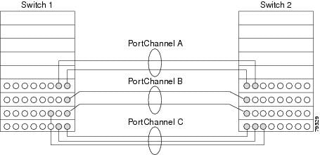
Port channels on Cisco MDS 9000 Series switches allow flexibility in configuration. This illustrates three possible port channel configurations:
- Port channel A aggregates two links on two interfaces on the same switching module at each end of a connection.
- Port channel B also aggregates two links, but each link is connected to a different switching module. If the switching module goes down, traffic is not affected. We recommend that you use the port channel B configuration for best result.
- Port channel C aggregates three links. Two links are on the same switching module at each end, while one is connected to a different switching module on switch 2.
Port Channeling and Trunking
Trunking is a commonly used storage industry term. However, the Cisco NX-OS software and switches in the Cisco MDS 9000 Series implement trunking and port channeling as follows:
- Port channeling enables several physical links to be combined into one aggregated logical link.
- Trunking enables a link transmitting frames in the EISL format to carry (trunk) multiple VSAN traffic. For example, when trunking is operational on an E port, that E port becomes a TE port. A TE port is specific to switches in the Cisco MDS 9000 Series. An industry standard E port can link to other vendor switches and is referred to as a nontrunking interface (See Figure 6-2 and Figure 6-3). See “Configuring Trunking,” for information on trunked interfaces.
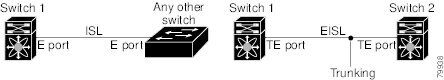
Figure 6-3 Port Channeling and Trunking
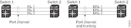
Port channeling and trunking are used separately across an ISL.
See the Cisco MDS 9000 Series NX-OS Fabric Configuration Guide.
Load Balancing
Two methods support the load-balancing functionality:
- Flow based—All frames between source and destination follow the same links for a given flow. That is, whichever link is selected for the first exchange of the flow is used for all subsequent exchanges.
- Exchange based—The first frame in an exchange picks a link and subsequent frames in the exchange follow the same link. However, subsequent exchanges can use a different link. This provides more granular load balancing while preserving the order of frames for each exchange.
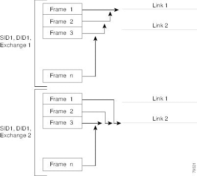
Figure 6-4 illustrates how source ID 1 (SID1) and destination ID1 (DID1) based load balancing works. When the first frame in a flow is received on an interface for forwarding, link 1 is selected. Each subsequent frame in that flow is sent over the same link. No frame in SID1 and DID1 utilizes link 2.
Figure 6-4 SID1 and DID1-Based Load Balancing
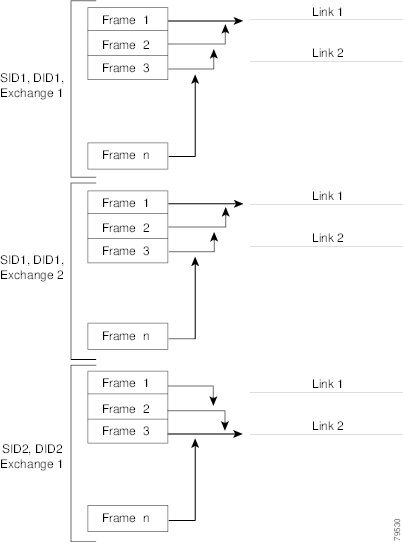
Figure 6-5 illustrates how exchange-based load balancing works. When the first frame in an exchange is received for forwarding on an interface, link 1 is chosen by a hash algorithm. All remaining frames in that particular exchange are sent on the same link. For exchange 1, no frame uses link 2. For the next exchange, link 2 is chosen by the hash algorithm. Now all frames in exchange 2 use link 2.
Figure 6-5 SID1, DID1, and Exchange-Based Load Balancing
For more information on configuring load balancing and in-order delivery features, see the Cisco MDS 9000 Series NX-OS Fabric Configuration Guide.
Port Channel Modes
You can configure each port channel with a channel group mode parameter to determine the port channel protocol behavior for all member ports in this channel group. The possible values for a channel group mode are as follows:
- ON (default)—The member ports only operate as part of a port channel or remain inactive. In this mode, the port channel protocol is not initiated. However, if a port channel protocol frame is received from a peer port, the software indicates its nonnegotiable status. This mode is backward compatible with the existing implementation of port channels in releases prior to Release 2.0(1b), where the channel group mode is implicitly assumed to be ON. In Cisco MDS SAN-OS Releases 1.3 and earlier, the only available port channel mode was the ON mode. Port channels configured in the ON mode require you to explicitly enable and disable the port channel member ports at either end if you add or remove ports from the port channel configuration. You must physically verify that the local and remote ports are connected to each other.
- ACTIVE—The member ports initiate port channel protocol negotiation with the peer port(s) regardless of the channel group mode of the peer port. If the peer port, while configured in a channel group, does not support the port channel protocol, or responds with a nonnegotiable status, it will default to the ON mode behavior. The ACTIVE port channel mode allows automatic recovery without explicitly enabling and disabling the port channel member ports at either end.
Table 6-1 compares ON and ACTIVE modes.
Valid and Invalid Port Channel Examples
Port channels are created with default values. You can change the default configuration just like any other physical interface.
Figure 6-6 provides examples of valid port channel configurations.
Figure 6-6 Valid Port Channel Configurations
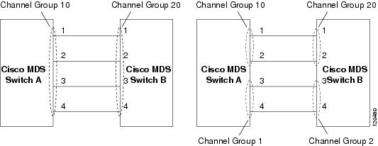
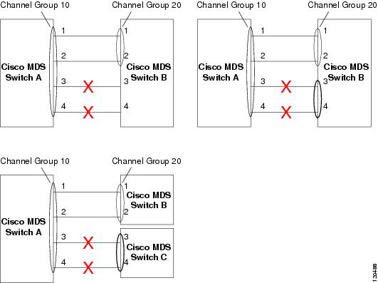
Figure 6-7 provides examples of invalid configurations. Assuming that the links are brought up in the 1, 2, 3, 4 sequence, links 3 and 4 will be operationally down as the fabric is misconfigured.
Figure 6-7 Misconfigured Configurations
Ethernet Port Channel

Note![]() Ethernet port channel is not supported for IP Storage port for MDS 9250i switch and Gigabit Ethernet ports for MDS 9000 Series switches.
Ethernet port channel is not supported for IP Storage port for MDS 9250i switch and Gigabit Ethernet ports for MDS 9000 Series switches.
Ethernet port channels offer link redundancy between the Cisco MDS 9000 Series switch’s FCoE Ethernet ports and the connecting Ethernet switch. Fibre Channel port channels also offer (E)ISL link redundancy between Fibre Channel switches. FCIP is an (E)ISL link and is only applicable for a Fibre Channel port channel. Beneath the FCIP level, an FCIP link can run on top of Gigabit Ethernet port. This link is totally transparent to the Fibre Channel layer.
Figure 6-8 displays an Ethernet port channel.
Figure 6-8 Ethernet Port Channel
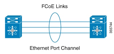
The following characteristics set Ethernet port channel solutions apart from other solutions:
- The FCoE Ethernet link-level redundancy ensures a transparent failover if one of the FCoE Ethernet links fails.
- Two FCoE Ethernet ports in one Ethernet port channel appear like one logical FCoE Ethernet link.
For configuration information, see “Configuring Ethernet Port Channels” section.
Ethernet Port Channel Load Balancing
The Cisco NX-OS software load balances traffic across all operational interfaces in a port channel by hashing the addresses in the frame to a numerical value that selects one of the links in the channel. Port channels provide load balancing by default. Port-channel load balancing uses MAC addresses, IP addresses, or Layer 4 port numbers to select the link. Port-channel load balancing uses either source or destination addresses or ports, or both source and destination addresses or ports.
You can configure the load- balancing mode to apply to all port channels that are configured on the entire device or on specified modules. The per-module configuration takes precedence over the load-balancing configuration for the entire device. You can configure one load-balancing mode for the entire device, a different mode for specified modules, and another mode for the other specified modules. You cannot configure the load-balancing method per port channel.
You can configure the type of load-balancing algorithm used. You can choose the load-balancing algorithm that determines which member port to select for egress traffic by looking at the fields in the frame.
Note![]() The default load-balancing mode for Layer 3 interfaces is the source and destination IP address, and the default load-balancing mode for non-IP traffic is the source and destination MAC address. Use the port-channel load-balance command to set the load-balancing method among the interfaces in the channel-group bundle. The default method for Layer 2 packets is src-dst-mac. The default method for Layer 3 packets is src-dst-ip.
The default load-balancing mode for Layer 3 interfaces is the source and destination IP address, and the default load-balancing mode for non-IP traffic is the source and destination MAC address. Use the port-channel load-balance command to set the load-balancing method among the interfaces in the channel-group bundle. The default method for Layer 2 packets is src-dst-mac. The default method for Layer 3 packets is src-dst-ip.
Ethernet Port Channel Aggregation
Ethernet port channels refer to the aggregation of multiple physical Gigabit Ethernet interfaces into one logical Ethernet interface to provide link redundancy and, in some cases, higher aggregated bandwidth and load balancing.
Note![]() The Cisco Ethernet switch’s port channel should be configured as a static port channel, and not the default 802.3ad protocol.
The Cisco Ethernet switch’s port channel should be configured as a static port channel, and not the default 802.3ad protocol.
Note![]() Port channel members must be one of these combinations: ports 1–2, ports 3–4, ports 5–6, or ports 7–8.
Port channel members must be one of these combinations: ports 1–2, ports 3–4, ports 5–6, or ports 7–8.
Fibre Channel Port Channel
Fibre Channel port channel is for both (E)ISL and F and TF for connections to Cisco NPV switches. Fibre Channel port channels can be comprised of either Fibre Channel interfaces or FCIP interfaces. FCIP is an (E)ISL link and is only applicable for a Fibre Channel port channel.
Fibre Channel and FCIP interfaces cannot be combined into one Fibre Channel port channel. Fibre Channel port channels must be comprised of either Fibre Channel or FCIP interfaces. The maximum number of Fibre Channel ports that can be put into a Fibre Channel port channel is 16.
E Port Channels
An E port channel refers to the aggregation of multiple E ports into one logical interface to provide higher aggregated bandwidth, load balancing, and link redundancy. Port channels can connect to interfaces across switching modules, so a failure of a switching module cannot bring down the port channel link.
A port channel has the following features and restrictions:
- Provides a point-to-point connection over ISL (E ports) or EISL (TE ports). Multiple links can be combined into a port channel.
- Increases the aggregate bandwidth on an ISL by distributing traffic among all functional links in the channel.
- Load balances across multiple links and maintains optimum bandwidth utilization. Load balancing is based on the source ID, destination ID, and exchange ID (OX ID).
- Provides high availability on an ISL. If one link fails, traffic previously carried on this link is switched to the remaining links. If a link goes down in a port channel, the upper protocol is not aware of it. To the upper protocol, the link is still there, although the bandwidth is diminished. The routing tables are not affected by link failure. Port channels may contain up to 16 physical links and may span multiple modules for added high availability.
Note![]() See the Cisco MDS 9000 Series NX-OS Fabric Configuration Guide for information about failover scenarios for port channels and FSPF links.
See the Cisco MDS 9000 Series NX-OS Fabric Configuration Guide for information about failover scenarios for port channels and FSPF links.
F and TF Port Channels
An F port channel is also a logical interface that combines a set of F ports connected to the same Fibre Channel node and operates as one link between the F ports and the NP ports. The F port channels support bandwidth utilization and availability like the E port channels. F port channels are mainly used to connect MDS core and NPV switches to provide optimal bandwidth utilization and transparent failover between the uplinks of a VSAN.
An F port channel trunk combines the functionality and advantages of a TF port and an F port channel. This logical link uses the Cisco PTP and PCP protocols over Cisco EPP (ELS).
Note![]() If a Cisco MDS 9124 or 9134 switch is used as a core switch, only a nontrunking F port channel is supported. Trunking is not supported on this platform when NPIV enabled.
If a Cisco MDS 9124 or 9134 switch is used as a core switch, only a nontrunking F port channel is supported. Trunking is not supported on this platform when NPIV enabled.
Port Channel Deletion
When you delete the port channel, the corresponding channel membership is also deleted. All interfaces in the deleted port channel convert to individual physical links. After the port channel is removed, regardless of the mode used (ACTIVE and ON), the ports at either end are gracefully brought down, indicating that no frames are lost when the interface is going down.
If you delete the port channel for one port, then the individual ports within the deleted port channel retain the compatibility parameter settings (speed, mode, port VSAN, allowed VSAN, and port security). You can explicitly change those settings as required.
Interfaces in a Port Channel
You can add or remove a physical interface (or a range of interfaces) to an existing port channel. The compatible parameters on the configuration are mapped to the port channel. Adding an interface to a port channel increases the total bandwidth of the port channel. Removing an interface from a port channel decreases the total bandwidth of the port channel.
Note![]() For information about port channel support on Generation 2 switching modules.
For information about port channel support on Generation 2 switching modules.
Interface Addition to a Port Channel
You can add a physical interface (or a range of interfaces) to an existing port channel. The compatible parameters on the configuration are mapped to the port channel. Adding an interface to a port channel increases the total bandwidth of the port channel.
A port can be configured as a member of a static port channel only if the following configurations are the same in the port and the port channel:
After the members are added, regardless of the mode (ACTIVE and ON) used, the ports at either end are gracefully brought down, indicating that no frames are lost when the interface is going down.
Compatibility Check
A compatibility check ensures that the same parameter settings are used in all physical ports in the channel. Otherwise, they cannot become part of a port channel. The compatibility check is performed before a port is added to the port channel.
The check ensures that the following parameters and settings match at both ends of a port channel:
- Capability parameters (type of interface, Gigabit Ethernet at both ends, or Fibre Channel at both ends).
- Administrative compatibility parameters (speed, mode, rate mode, port VSAN, allowed VSAN list, and port security).
Note![]() Ports in shared rate mode cannot form a port channel or a trunking port channel.
Ports in shared rate mode cannot form a port channel or a trunking port channel.
A port addition procedure fails if the capability and administrative parameters in the remote switch are incompatible with the capability and administrative parameters in the local switch. If the compatibility check is successful, the interfaces are operational and the corresponding compatibility parameter settings apply to these interfaces.
Suspended and Isolated States
If the operational parameters are incompatible, the compatibility check fails and the interface is placed in a suspended or isolated state based on the configured mode:
Forcing an Interface Addition
You can force the port configuration to be overwritten by the port channel. In this case, the interface is added to a port channel.
- If you use the default ON mode to avoid inconsistent states across switches and to maintain consistency across switches, then the ports shut down. You must explicitly enable those ports again.
- If you use the ACTIVE mode, then the port channel ports automatically recover from the addition.
Note![]() When port channels are created from within an interface, the force option cannot be used.
When port channels are created from within an interface, the force option cannot be used.
After the members are forcefully added, regardless of the mode (ACTIVE and ON) used, the ports at either end are gracefully brought down, indicating that no frames are lost when the interface is going down.
Deleting Interface from a Port Channel
When a physical interface is deleted from the port channel, the channel membership is automatically updated. If the deleted interface is the last operational interface, then the port channel status is changed to a down state. Deleting an interface from a port channel decreases the total bandwidth of the port channel.
- If you use the default ON mode to avoid inconsistent states across switches and to maintain consistency across switches, then the ports shut down. You must explicitly enable those ports again.
- If you use the ACTIVE mode, then the port channel ports automatically recover from the deletion.
After the members are deleted, regardless of the mode (ACTIVE and ON) used, the ports at either end are gracefully brought down, indicating that no frames are lost when the interface is going down.
Port Channel Protocols
In earlier Cisco SAN-OS releases, port channels required additional administrative tasks to support synchronization. The Cisco NX-OS software provides robust error detection and synchronization capabilities. Any change in configuration applied to the associated port channel interface is propagated to all members of the channel group.
A protocol to exchange port channel configurations is available in all Cisco MDS switches. This addition simplifies port channel management with incompatible ISLs.
The port channel protocol is enabled by default.
The port channel protocol expands the port channel functional model in Cisco MDS switches. It uses the exchange peer parameters (EPP) services to communicate across peer ports in an ISL. Each switch uses the information received from the peer ports along with its local configuration and operational values to decide if it should be part of a port channel. The protocol ensures that a set of ports are eligible to be part of the same port channel. They are only eligible to be part of the same port channel if all the ports have a compatible partner.
The port channel protocol uses the following subprotocol:
Bringup protocol—Automatically detects misconfigurations so you can correct them. This protocol synchronizes the port channel at both ends so that all frames for a given flow (as identified by the source FC ID, destination FC ID and OX_ID) are carried over the same physical link in both directions. This helps make applications such as write acceleration, work for port channels over FCIP links.
Prerequisites for Port Channels
Before configuring a port channel, consider the following guidelines:
- Configure the port channel across switching modules to implement redundancy on switching module reboots or upgrades.
- Ensure that one port channel is not connected to different sets of switches. Port channels require point-to-point connections between the same set of switches.
Note![]() On switches with Generation 1 switching modules, or a combination of Generation 1 and Generation 2 switching modules, you can configure a maximum of 128 port channels. On switches with only Generation 2 switching modules, or Generation 2 and Generation 3 switching modules, you can configure a maximum of 256 port channels.
On switches with Generation 1 switching modules, or a combination of Generation 1 and Generation 2 switching modules, you can configure a maximum of 128 port channels. On switches with only Generation 2 switching modules, or Generation 2 and Generation 3 switching modules, you can configure a maximum of 256 port channels.
If you misconfigure port channels, you may receive a misconfiguration message. If you receive this message, the port channel’s physical links are disabled because an error has been detected.
A port channel error is detected if the following requirements are not met:
- Each switch on either side of a port channel must be connected to the same number of interfaces.
- Each interface must be connected to a corresponding interface on the other side (see Figure 6-7 for an example of an invalid configuration).
- Links in a port channel cannot be changed after the port channel is configured. If you change the links after the port channel is configured, be sure to reconnect the links to interfaces within the port channel and reenable the links.
If all three conditions are not met, the faulty link is disabled.
Enter the show interface command for that interface to verify that the port channel is functioning as required.
Guidelines and Limitations
This section includes the guidelines and limitations for this feature:
- General Guidelines and Limitations
- Guidelines and Limitations for vFC
- F and TF Port Channel Limitations
- Valid and Invalid Port Channel Examples
General Guidelines and Limitations
Cisco MDS 9000 Series switches support the following number of port channels per switch:
- Switches with only Generation 1 switching modules do not support F and TF port channels.
- Switches with Generation 1 switching modules, or a combination of Generation 1 and Generation 2 switching modules, support a maximum of 128 port channels. Only Generation 2 ports can be included in the port channels.
- Switches with only Generation 2 switching modules or Generation 2 and Generation 3 modules support a maximum of 256 port channels with 16 interfaces per port channel.
- A port channel number refers to the unique identifier for each channel group. This number ranges from of 1 to 256.
- The compatibility parameters on both side of the port channel must match.
Guidelines and Limitations for vFC
When configuring vFC interfaces, note the following guidelines and limitations:
–![]() A media access control (MAC) address of an FCoE Node (ENode) or a remote Fibre Channel Forwarder (FCF) identified by the virtual FC interface
A media access control (MAC) address of an FCoE Node (ENode) or a remote Fibre Channel Forwarder (FCF) identified by the virtual FC interface
F and TF Port Channel Limitations
The following guidelines and restrictions are applicable for F and TF port channels:
- The ports must be in F mode.
- The port channel interface must be in ACTIVE mode when multiple FCIP interfaces are grouped with WA.
- ON mode is not supported. Only ACTIVE-ACTIVE mode is supported. By default, the mode is ACTIVE on the NPV switches.
- Devices logged in through F port channel on an MDS switch are not supported in IVR non-NAT configuration. The devices are supported only in IVR NAT configuration.
- Port security rules are enforced only on physical pWWNs at the single link level.
- FC-SP authenticates only the first physical FLOGI of every port channel member.
- Since the FLOGI payload carries only the VF bits to trigger the use of a protocol after the FLOGI exchange, those bits will be overridden. In the case of the NPV switches, the core has a Cisco WWN and will try to initiate the PCP protocol.
- The name server registration of the N ports logging in through an F port channel will use the fWWN of the port channel interface.
- DPVM configuration is not supported.
- The port channel port VSAN cannot be configured using DPVM.
- The Dynamic Port VSAN Management (DPVM) database will be queried only for the first physical FLOGI of each member, so that the port VSAN can be configured automatically.
- DPVM does not bind FC_IDs to VSANs, but pWWNs to VSANs. It will be queried only for the physical FLOGI.
Default Settings
Table 6-2 lists the default settings for port channels.
|
|
|
|---|---|
Configuring Fibre Channel Port Channels
This section includes the following topics:
- Configuring a Fibre Channel Port Channels
- Configuring the Fibre Channel Port Channel Mode
- Deleting Fibre Channel Port Channels
- Adding an Interface to a Fibre Channel Port Channel
- Forcing an Interface Addition
- Deleting an Interface from a Fibre Channel Port Channel
Configuring a Fibre Channel Port Channels
Detailed Steps
To create a port channel, follow these steps:
|
|
|
|
|---|---|---|
Configures the specified port channel (1) using the default ON mode. |
Configuring the Fibre Channel Port Channel Mode
By default, the CLI and the Device Manager create the port channel in ON mode in the NPIV core switches and ACTIVE mode on the NPV switches. DCNM-SAN creates all port channels in ACTIVE mode. We recommend that you create port channels in ACTIVE mode.
Restrictions
Detailed Steps
To configure ACTIVE mode, follow these steps:
|
|
|
|
|---|---|---|
Configures the specified port channel (1) using the default ON mode. |
||
Deleting Fibre Channel Port Channels
Detailed Steps
To delete a port channel, follow these steps:
Adding an Interface to a Fibre Channel Port Channel
Detailed Steps
To add an interface to a port channel, follow these steps:
|
|
|
|
|---|---|---|
Adds physical Fibre Channel port 1/15 to channel group 15. If channel group 15 does not exist, it is created. The port is shut down. |
To add a range of ports to a port channel, follow these steps:
Note![]() By default, the CLI adds a interface normally to a port channel, while DCNM-SAN adds the interface by force, unless specified explicitly.
By default, the CLI adds a interface normally to a port channel, while DCNM-SAN adds the interface by force, unless specified explicitly.
Forcing an Interface Addition
Detailed Steps
To force the addition of a port to a port channel, follow these steps:
|
|
|
|
|---|---|---|
Forces the addition of the physical port for interface fc1/1 to channel group 1. The port is shut down. |
Deleting an Interface from a Fibre Channel Port Channel
Detailed Steps
To delete a physical interface (or a range of physical interfaces) from a port channel, follow these steps:
|
|
|
|
|---|---|---|
Deletes the physical Fibre Channel interfaces in channel group 2. |
Verifying Port Channel Configuration
To display port channel configuration information, perform one of the following tasks:
|
|
|
|---|---|
Displays the port channel configured in the default ON mode and ACTIVE mode. |
|
Displays the Ethernet port channel group, port channel, type, protocol and member ports. |
|
For detailed information about the fields in the output from these commands, refer to the Cisco MDS NX-OS Command Reference.
You can view specific information about existing port channels at any time from EXEC mode. The following show commands provide further details on existing port channels. You can force all screen output to go to a printer or save it to a file. See Examples 6-1 to 6-6 .
Example 6-1 Displays the Port Channel Summary
------------------------------------------------------------------------------
Example 6-2 Displays the Configured in the Default ON Mode
Example 6-3 Displays the Port Channel Configured in the ACTIVE Mode
The show port-channel consistency command has two options: without details and with details.
Example 6-4 Displays the Consistency Status without Details
Example 6-5 Displays the Consistency Status with Details
The show port-channel usage command displays details of the used and unused port channel numbers.
Example 6-6 Displays the Port Channel Usage
Totally 3 port-channel numbers used
Example 6-7 Displays the Port Channel Compatibility
Example 6-8 Displays the Port Channel Summary
Configuration Examples for F and TF Port Channels
This example shows how to configure F port channel in shared mode and bring up the link between F ports on the NPIV core switches and NP ports on the NPV switches:
Note Port channel in shared mode is not supported on the MDS 91x4 switches.
Figure 6-9 Port Channel Link Between F Ports on NPIV Core switch and NP Ports on NPV Switch

Step 1![]() Enable the F port trunking and channeling protocol on the MDS core switch.
Enable the F port trunking and channeling protocol on the MDS core switch.
Step 2![]() Enable NPIV on the MDS core switch:
Enable NPIV on the MDS core switch:
Step 3![]() Create the port channel on the MDS core switch:
Create the port channel on the MDS core switch:
Step 4![]() Configure the port channel member interfaces on the core switch:
Configure the port channel member interfaces on the core switch:
Step 5![]() Create the port channel on the NPV switch:
Create the port channel on the NPV switch:
Step 6![]() Configure the port channel member interfaces on the NPV switch:
Configure the port channel member interfaces on the NPV switch:
Step 7![]() Set the administrative state of all the port channel member interfaces in both NPIV core switch and the NPV switch to ON:
Set the administrative state of all the port channel member interfaces in both NPIV core switch and the NPV switch to ON:
Note![]() The speed configuration must be the same for all member interfaces in a port channel. While configuring the channel in dedicated mode, ensure that required bandwidth is available to the ports.
The speed configuration must be the same for all member interfaces in a port channel. While configuring the channel in dedicated mode, ensure that required bandwidth is available to the ports.
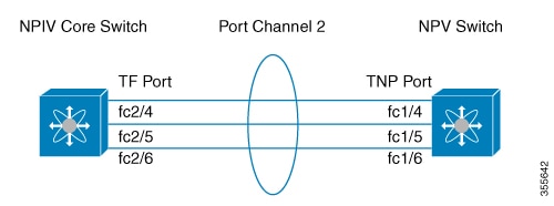
This example shows how to configure channeling in dedicated mode and bring up the TF-TNP port channel link between TF ports in the NPIV core switch, and TNP ports in the NPV switch:
Figure 6-10 Port Channel Link Between TF Ports on NPIV Core switch and TNP Ports on NPV Switch
Step 1![]() Enable the F port trunking and channeling protocol on the MDS core switch:
Enable the F port trunking and channeling protocol on the MDS core switch:
Step 2![]() Enable NPIV on the MDS core switch:
Enable NPIV on the MDS core switch:
Step 3![]() Create the port channel on the MDS core switch:
Create the port channel on the MDS core switch:
Step 4![]() Configure the port channel member interfaces on the MDS core switch in dedicated mode:
Configure the port channel member interfaces on the MDS core switch in dedicated mode:
Step 5![]() Create the port channel in dedicated mode on the NPV switch:
Create the port channel in dedicated mode on the NPV switch:
Step 6![]() Configure the port channel member interfaces on the NPV switch in dedicated mode:
Configure the port channel member interfaces on the NPV switch in dedicated mode:
Step 7![]() Set the administrative state of all the port channel member interfaces in both NPIV core switch and the NPV switch to ON:
Set the administrative state of all the port channel member interfaces in both NPIV core switch and the NPV switch to ON:
Configuring Ethernet Port Channels
This section includes the following topics:
- Configuring Ethernet Port Channels
- Deleting Ethernet Port Channels
- Adding an Interface to a Ethernet Port Channel
- Forcing an Interface Addition to an Ethernet Port Channel
- Deleting an Interface from an Ethernet Port Channel
Configuring Ethernet Port Channels
Detailed Steps
To create a Ethernet port channel, follow these steps:
|
|
|
|
|---|---|---|
Configures the specified Ethernet port channel using the default ON mode. |
Note Ethernet port-channels are not supported on the following:
Deleting Ethernet Port Channels
Detailed Steps
To delete a Ethernet port channel, follow these steps:
|
|
|
|
|---|---|---|
Deletes the specified Ethernet port channel, its associated interface mappings, and the hardware associations for this Ethernet port channel. |
Adding an Interface to a Ethernet Port Channel
Detailed Steps
To add an interface to a Ethernet port channel, follow these steps:
|
|
|
|
|---|---|---|
To add a range of ports to a Ethernet port channel, follow these steps:
|
|
|
|
|---|---|---|
By default, the CLI adds a interface normally to a Ethernet port channel, while DCNM-SAN adds the interface by force, unless specified explicitly.
Specifying a Channeling Mode for an Ethernet Interface
Note![]() We recommend that you create Ethernet port channels in Active mode.
We recommend that you create Ethernet port channels in Active mode.
Detailed Steps
To specify a channeling mode for an Ethernet interface, follow these steps:
|
|
|
|
|---|---|---|
switch(config-if)# channel-group 513 mode active |
Forcing an Interface Addition to an Ethernet Port Channel
Detailed Steps
To force the addition of a port to a Ethernet port channel, follow these steps:
|
|
|
|
|---|---|---|
Forces the addition of a port for interface ethernet-port-channel to a channel group. The port is shut down. |
Deleting an Interface from an Ethernet Port Channel
Detailed Steps
To delete an interface (or a range of physical interfaces) from a Ethernet port channel, follow these steps:
|
|
|
|
|---|---|---|
Deletes the Ethernet port channel interfaces in channel group 2. |
Verifying Ethernet Port Channel Configuration
To display Ethernet port channel configuration information, perform one of the following tasks:
|
|
|
|---|---|
Displays the Ethernet port channel group, port channel, type, protocol and member ports. |
|
show ethernet-port-channel database interface port-channel number |
You can view specific information about existing Ethernet port channels at any time from EXEC mode. The following show commands provide further details on existing Ethernet port channels. You can force all screen output to go to a printer or save it to a file.
Example 6-9 Displays the Ethernet Port Channel Summary
Flags: D - Down P - Up in port-channel (members)
Example 6-10 Displays the Ethernet Port Channel Database
ethernet-port-channel513
The show ethernet-port-channel command displays details of used and unused Ethernet port channel numbers:
Example 6-11 Displays the Ethernet Port Channel Usage
switch# show ethernet-port-channel usage
Configuring Virtual Fibre Channel (vFC) Interfaces for FCoE
This section includes the following topics:
- Creating an Explicit Virtual Fibre Channel Interface
- Creating an Implicit Virtual Fibre Channel Port Channel Interface
- Verifying the Virtual Interface
Creating an Explicit Virtual Fibre Channel Interface
An explicit vFC interface is a vFC interface where the bound Ethernet or port-channel interface is explicitly configured. To can create an explicit vFC interface you must bind the vFC interface to a physical interface before it can be used. If you want the vFC interface to automatically bound to the port-channel interface, see Creating an Implicit Virtual Fibre Channel Port Channel Interface.
Before You Begin
This example shows how to bind a virtual Fibre Channel interface to an Ethernet interface:
This example shows how to delete a virtual Fibre Channel interface:
Creating an Implicit Virtual Fibre Channel Port Channel Interface
An implicit VFC interface is a VFC interface that has an ID with the format slot/port, unit/slot/port, or port-channel id. When this VFC is created, the ethernet interface slot/port or unit/slot/port or port-channel id is automatically (implicitly) bound to the interface. You can create a virtual Fibre Channel port channel interface that automatically binds to the port channel with the same interface number.
Before You Begin
For the Cisco MDS 9700 switches, MDS 9500 switches, and MDS 9250i switch, ensure that you create the Ethernet port channel interface before you create the virtual Fibre Channel port channel interface.
Verifying the Virtual Interface
To display configuration information about virtual interfaces, perform one of the following tasks:
|
|
|
|---|---|
Displays the detailed configuration of the specified Fibre Channel interface. |
|
This example shows how to display a virtual Fibre Channel interface bound to an Ethernet interface:
This example shows how to display the status of all the interfaces on the switch (some output has been removed for brevity):
This example shows how to display the mapping between the VLANs and VSANs on the switch:
 Feedback