Cisco Nexus 7000 シリーズ NX-OS レイヤ 2 スイッチング コンフィギュレーション ガイド
偏向のない言語
この製品のマニュアルセットは、偏向のない言語を使用するように配慮されています。このマニュアルセットでの偏向のない言語とは、年齢、障害、性別、人種的アイデンティティ、民族的アイデンティティ、性的指向、社会経済的地位、およびインターセクショナリティに基づく差別を意味しない言語として定義されています。製品ソフトウェアのユーザーインターフェイスにハードコードされている言語、RFP のドキュメントに基づいて使用されている言語、または参照されているサードパーティ製品で使用されている言語によりドキュメントに例外が存在する場合があります。シスコのインクルーシブランゲージに対する取り組みの詳細は、こちらをご覧ください。
翻訳について
このドキュメントは、米国シスコ発行ドキュメントの参考和訳です。リンク情報につきましては、日本語版掲載時点で、英語版にアップデートがあり、リンク先のページが移動/変更されている場合がありますことをご了承ください。あくまでも参考和訳となりますので、正式な内容については米国サイトのドキュメントを参照ください。
- Updated:
- 2017年6月22日
章のタイトル: Cisco NX-OS を使用した MST の設定
目次
- Cisco NX-OS を使用した MST の設定
- Information About MST
- MST Overview
- MST Regions
- MST BPDUs
- MST Configuration Information
- IST, CIST, and CST
- IST, CIST, and CST Overview
- Spanning Tree Operation Within an MST Region
- Spanning Tree Operations Between MST Regions
- MST Terminology
- Hop Count
- 境界ポート
- Detecting Unidirectional Link Failure:MST
- Port Cost and Port Priority
- Interoperability with IEEE 802.1D
- High Availability for MST
- Virtualization Support for MST
- Licensing Requirements for MST
- Prerequisites for MST
- Guidelines and Limitations for Configuring MST
- MST のデフォルト設定
- Configuring MST
- MST のイネーブル化(CLI バージョン)
- MST コンフィギュレーション モードの開始
- MST の名前の指定
- MST 設定のリビジョン番号の指定
- MST 領域での設定の指定
- VLAN と MST インスタンスのマッピングおよびマッピング解除(CLI バージョン)
- プライベート VLAN でセカンダリ VLAN をプライマリ VLAN として同じ MSTI にマッピングするには
- ルート ブリッジの設定
- MST セカンダリ ルート ブリッジの設定
- MST スイッチ プライオリティの設定
- MST ポート プライオリティの設定
- MST ポート コストの設定
- MST hello タイムの設定
- MST 転送遅延時間の設定
- MST 最大エージング タイムの設定
- MST 最大ホップ カウントの設定
- 先行標準 MSTP メッセージを事前に送信するインターフェイスの設定(CLI バージョン)
- MST のリンク タイプの指定(CLI バージョン)
- MST 用のプロトコルの再初期化
- MST 設定の確認
- MST 統計情報の表示およびクリア(CLI バージョン)
- MST の設定例
- MST の追加情報(CLI バージョン)
- MST 設定の機能履歴(CLI バージョン)
この章では、Cisco NX-OS デバイス上でマルチ スパニングツリー(MST)を設定する方法について説明します。
この章は、次の内容で構成されています。
- Information About MST
- Licensing Requirements for MST
- Prerequisites for MST
- Guidelines and Limitations for Configuring MST
- MST のデフォルト設定
- Configuring MST
- MST 設定の確認
- MST 統計情報の表示およびクリア(CLI バージョン)
- MST の設定例
- MST の追加情報(CLI バージョン)
- MST 設定の機能履歴(CLI バージョン)
Information About MST
 (注) |
See the 『Cisco Nexus 7000 Series NX-OS Interfaces Configuration Guide, Release 6.x』, for information on creating Layer 2 interfaces. |
MST, which is the IEEE 802.1s standard, allows you to assign two or more VLANs to a spanning tree instance. MST is not the default spanning tree mode; Rapid per VLAN Spanning Tree (Rapid PVST+) is the default mode. MST instances with the same name, revision number, and VLAN-to-instance mapping combine to form an MST region. The MST region appears as a single bridge to spanning tree configurations outside the region. MST forms a boundary to that interface when it receives an IEEE 802.1D Spanning Tree Protocol (STP) message from a neighboring device.
(注) |
Spanning tree is used to refer to IEEE 802.1w and IEEE 802.1s. If the IEEE 802.1D Spanning Tree Protocol is discussed in this publication, 802.1D is stated specifically. |
(注) |
Beginning with Cisco NX-OS Release 5.x, when you are running virtual port channels (vPCs), you can configure STP for better performance. See the 『Cisco Nexus 7000 Series NX-OS Interfaces Configuration Guide, Release 6.x』, for more information on this feature. |
- MST Overview
- MST Regions
- MST BPDUs
- MST Configuration Information
- IST, CIST, and CST
- Hop Count
- 境界ポート
- Detecting Unidirectional Link Failure:MST
- Port Cost and Port Priority
- Interoperability with IEEE 802.1D
- High Availability for MST
- Virtualization Support for MST
MST Overview
(注) |
You must enable MST; Rapid PVST+ is the default spanning tree mode. |
MST maps multiple VLANs into a spanning tree instance, with each instance having a spanning tree topology independent of other spanning tree instances. This architecture provides multiple forwarding paths for data traffic, enables load balancing, and reduces the number of STP instances required to support a large number of VLANs. MST improves the fault tolerance of the network because a failure in one instance (forwarding path) does not affect other instances (forwarding paths).
MST provides rapid convergence through explicit handshaking because each MST instance uses the IEEE 802.1w standard, which eliminates the 802.1D forwarding delay and quickly transitions root bridge ports and designated ports to the forwarding state.
MAC address reduction is always enabled on the device. You cannot disable this feature.
MST improves spanning tree operation and maintains backward compatibility with these STP versions:
(注) |
|
MST Regions
To allow devices to participate in MST instances, you must consistently configure the devices with the same MST configuration information.
A collection of interconnected devices that have the same MST configuration is an MST region. An MST region is a linked group of MST bridges with the same MST configuration.
The MST configuration controls the MST region to which each device belongs. The configuration includes the name of the region, the revision number, and the VLAN-to-MST instance assignment mapping.
A region can have one or multiple members with the same MST configuration. Each member must be capable of processing 802.1w bridge protocol data units (BPDUs). There is no limit to the number of MST regions in a network.
Each device can support up to 65 MST instances (MSTIs), including Instance 0, in a single MST region. Instances are identified by any number in the range from 1 to 4094. The system reserves Instance 0 for a special instance, which is the IST. You can assign a VLAN to only one MST instance at a time.
The MST region appears as a single bridge to adjacent MST regions and to other Rapid PVST+ regions and 802.1D spanning tree protocols.
(注) |
We do not recommend that you partition the network into a large number of regions. |
MST BPDUs
Each device has only one MST BPDU per interface, and that BPDU carries an M-record for each MSTI on the device. Only the IST sends BPDUs for the MST region; all M-records are encapsulated in that one BPDU that the IST sends. Because the MST BPDU carries information for all instances, the number of BPDUs that need to be processed to support MST is significantly reduced compared with Rapid PVST+.
MST Configuration Information
The MST configuration that must be identical on all devices within a single MST region is configured by the user.
You can configure the three parameters of the MST configuration as follows:
- Name—32-character string, null padded and null terminated, identifying the MST region
- Revision number—Unsigned 16-bit number that identifies the revision of the current MST configuration
(注) |
You must set the revision number when required as part of the MST configuration. The revision number is not incremented automatically each time that the MST configuration is committed. |
- VLAN-to-MST instance mapping—4096-element table that associates each of the potential 4094 VLANs supported in each virtual device context (VDC) to a given instance with the first (0) and last element (4095) set to 0. The value of element number X represents the instance to which VLAN X is mapped.
(注) |
When you change the VLAN-to-MSTI mapping, the system reconverges MST. |
MST BPDUs contain these three configuration parameters. An MST bridge accepts an MST BPDU into its own region only if these three configuration parameters match exactly. If one configuration attribute differs, the MST bridge considers the BPDU to be from another MST region.
IST, CIST, and CST
- IST, CIST, and CST Overview
- Spanning Tree Operation Within an MST Region
- Spanning Tree Operations Between MST Regions
- MST Terminology
IST, CIST, and CST Overview
Unlike Rapid PVST+, in which all the STP instances are independent, MST establishes and maintains IST, CIST, and CST spanning trees, as follows:
- An IST is the spanning tree that runs in an MST region. MST establishes and maintains additional spanning trees within each MST region; these spanning trees are called multiple spanning tree instances (MSTIs). Instance 0 is a special instance for a region, known as the IST. The IST always exists on all ports; you cannot delete the IST, or Instance 0. By default, all VLANs are assigned to the IST. All other MST instances are numbered from 1 to 4094. The IST is the only STP instance that sends and receives BPDUs. All of the other MSTI information is contained in MST records (M-records), which are encapsulated within MST BPDUs. All MSTIs within the same region share the same protocol timers, but each MSTI has its own topology parameters, such as the root bridge ID, the root path cost, and so forth. An MSTI is local to the region; for example, MSTI 9 in region A is independent of MSTI 9 in region B, even if regions A and B are interconnected. Only CST information crosses region boundaries.
- The CST interconnects the MST regions and any instance of 802.1D and 802.1w STP that may be running on the network. The CST is the one STP instance for the entire bridged network and encompasses all MST regions and 802.1w and 802.1D instances.
- A CIST is a collection of the ISTs in each MST region. The CIST is the same as an IST inside an MST region, and the same as a CST outside an MST region.
The spanning tree computed in an MST region appears as a subtree in the CST that encompasses the entire switched domain. The CIST is formed by the spanning tree algorithm running among devices that support the 802.1w, 802.1s, and 802.1D standards. The CIST inside an MST region is the same as the CST outside a region.
Spanning Tree Operation Within an MST Region
The IST connects all the MSTdevices in a region. When the IST converges, the root of the IST becomes the CIST regional root. The CIST regional root is also the CIST root if there is only one region in the network. If the CIST root is outside the region, the protocol selects one of the MST devices at the boundary of the region as the CIST regional root.
When an MST device initializes, it sends BPDUs that identify itself as the root of the CIST and the CIST regional root, with both the path costs to the CIST root and to the CIST regional root set to zero. The device also initializes all of its MSTIs and claims to be the root for all of them. If the device receives superior MSTI root information (lower switch ID, lower path cost, and so forth) than the information that is currently stored for the port, it relinquishes its claim as the CIST regional root.
During initialization, an MST region might have many subregions, each with its own CIST regional root. As devices receive superior IST information from a neighbor in the same region, they leave their old subregions and join the new subregion that contains the true CIST regional root. This action causes all subregions to shrink except for the subregion that contains the true CIST regional root.
All devices in the MST region must agree on the same CIST regional root. Any two devices in the region will only synchronize their port roles for an MSTI if they converge to a common CIST regional root.
Spanning Tree Operations Between MST Regions
If you have multiple regions or 802.1 w or 802.1D STP instances within a network, MST establishes and maintains the CST, which includes all MST regions and all 802.1w and 802.1D STP devices in the network. The MSTIs combine with the IST at the boundary of the region to become the CST.
The IST connects all the MST devices in the region and appears as a subtree in the CIST that encompasses the entire switched domain. The root of the subtree is the CIST regional root. The MST region appears as a virtual device to adjacent STP devices and MST regions.
Only the CST instance sends and receives BPDUs. MSTIs add their spanning tree information into the BPDUs (as M-records) to interact with neighboring devices within the same MST region and compute the final spanning tree topology. The spanning tree parameters related to the BPDU transmission (for example, hello time, forward time, max-age, and max-hops) are configured only on the CST instance but affect all MSTIs. You can configure the parameters related to the spanning tree topology (for example, the switch priority, the port VLAN cost, and the port VLAN priority) on both the CST instance and the MSTI.
MST devices use Version 3 BPDUs. If the MST device falls back to 802.1D STP, the device uses only 802.1D BPDUs to communicate with 802.1D-only devices. MST devices use MST BPDUs to communicate with MST devices.
MST Terminology
MST naming conventions include identification of some internal or regional parameters. These parameters are used only within an MST region, compared to external parameters that are used throughout the whole network. Because the CIST is the only spanning tree instance that spans the whole network, only the CIST parameters require the external qualifiers and not the internal or regional qualifiers. The MST terminology is as follows:
- The CIST root is the root bridge for the CIST, which is the unique instance that spans the whole network.
- The CIST external root path cost is the cost to the CIST root. This cost is left unchanged within an MST region. An MST region looks like a single device to the CIST. The CIST external root path cost is the root path cost calculated between these virtual devices and devices that do not belong to any region.
- If the CIST root is in the region, the CIST regional root is the CIST root. Otherwise, the CIST regional root is the closest device to the CIST root in the region. The CIST regional root acts as a root bridge for the IST.
- The CIST internal root path cost is the cost to the CIST regional root in a region. This cost is only relevant to the IST, instance 0.
Hop Count
MST does not use the message-age and maximum-age information in the configuration BPDU to compute the STP topology inside the MST region. Instead, the protocol uses the path cost to the root and a hop-count mechanism similar to the IP time-to-live (TTL) mechanism.
By using the spanning-tree mst max-hops global configuration command, you can configure the maximum hops inside the region and apply it to the IST and all MST instances in that region.
The hop count achieves the same result as the message-age information (triggers a reconfiguration). The root bridge of the instance always sends a BPDU (or M-record) with a cost of 0 and the hop count set to the maximum value. When a device receives this BPDU, it decrements the received remaining hop count by one and propagates this value as the remaining hop count in the BPDUs that it generates. When the count reaches zero, the device discards the BPDU and ages the information held for the port.
The message-age and maximum-age information in the 802.1w portion of the BPDU remain the same throughout the region (only on the IST), and the same values are propagated by the region-designated ports at the boundary.
You configure a maximum aging time as the number of seconds that a device waits without receiving spanning tree configuration messages before attempting a reconfiguration.
境界ポート
境界ポートは、LAN に接続されたポートで、その代表ブリッジは、MST 設定が異なるブリッジ(つまり、別の MST 領域)、または Rapid PVST+ や 802.1D STP スイッチのいずれかです。 指定ポートは、STP ブリッジを検出するか、設定が異なる MST ブリッジまたは Rapid PVST+ ブリッジから合意提案を受信すると、境界にあることを認識します。 この定義では、領域内部の 2 つのポートが、別の領域に属するポートとセグメントを共有でき、そのため内部メッセージおよび外部メッセージの両方をポートで受信する可能性があります。
境界では、MST ポートのロールは問題ではなく、そのステートは強制的に IST ポート ステートと同じに設定されます。 境界フラグがポートに対してオンに設定されている場合、MST ポートのロールの選択処理では、ポートのロールが境界に割り当てられ、同じステートが IST ポートのステートとして割り当てられます。 境界にある IST ポートでは、バックアップ ポートのロール以外のすべてのポートのロールを引き継ぐことができます。
Detecting Unidirectional Link Failure:MST
Currently, this feature is not present in the IEEE MST standard, but it is included in the standard-compliant implementation; it is based on the dispute mechanism. The software checks the consistency of the port role and state in the received BPDUs to detect unidirectional link failures that could cause bridging loops. This feature is based on the dispute mechanism.
(注) |
See the 『Cisco Nexus 7000 Series NX-OS Interfaces Configuration Guide, Release 6.x』, for information on Unidirectional Link Detection (UDLD). |
When a designated port detects a conflict, it keeps its role, but reverts to a discarding state because disrupting connectivity in case of inconsistency is preferable to opening a bridging loop.
This figure shows a unidirectional link failure that typically creates a bridging loop. Switch A is the root bridge, and its BPDUs are lost on the link leading to switch B. Rapid PVST+ (802.1w) and MST BPDUs include the role and state of the sending port. With this information, switch A can detect that switch B does not react to the superior BPDUs that it sends and that switch B is the designated, not root port. As a result, switch A blocks (or keeps blocking) its port, which prevents the bridging loop.
Port Cost and Port Priority
Spanning tree uses port costs to break a tie for the designated port. Lower values indicate lower port costs, and spanning tree chooses the least costly path. Default port costs are taken from the bandwidth of the interface, as follows:
You can configure the port costs in order to influence which port is chosen.
(注) |
MST always uses the long path-cost calculation method, so the range of valid values is between 1 and 200,000,000. |
The system uses port priorities to break ties among ports with the same cost. A lower number indicates a higher priority. The default port priority is 128. You can configure the priority to values between 0 and 224, in increments of 32.
Interoperability with IEEE 802.1D
A device that runs MST supports a built-in protocol migration feature that enables it to interoperate with 802.1D STP devices. If this devoce receives an 802.1D configuration BPDU (a BPDU with the protocol version set to 0), it sends only 802.1D BPDUs on that port. In addition, an MST device can detect that a port is at the boundary of a region when it receives an 802.1D BPDU, an MST BPDU (Version 3) associated with a different region, or an 802.1w BPDU (Version 2).
However, the device does not automatically revert to the MST mode if it no longer receives 802.1D BPDUs because it cannot detect whether the 802.1D device has been removed from the link unless the 802.1D device is the designated device. A device might also continue to assign a boundary role to a port when the device to which this device is connected has joined the region.
To restart the protocol migration process (force the renegotiation with neighboring devices), enter the clear spanning-tree detected-protocols command.
All Rapid PVST+ switches (and all 8021.D STP switches) on the link can process MST BPDUs as if they are 802.1w BPDUs. MST devices can send either Version 0 configuration and topology change notification (TCN) BPDUs or Version 3 MST BPDUs on a boundary port. A boundary port connects to a LAN, the designated device of which is either a single spanning tree device or a device with a different MST configuration.
MST interoperates with the Cisco prestandard MSTP whenever it receives prestandard MSTP on an MST port; no explicit configuration is necessary. In Cisco NX-OS Release 4.0(2) and later releases, you can configure specified interfaces to send prestandard MSTP messages all the time; it does not have to wait to receive a prestandard MST message to begin sending prestandard MST messages.
You can also configure the interface to proactively send prestandard MSTP messages.
High Availability for MST
The software supports high availability for MST. However, the statistics and timers are not restored when MST restarts. The timers start again and the statistics begin from 0.
The device supports full nondisruptive upgrades for MST. See the 『Cisco Nexus 7000 Series NX-OS High Availability and Redundancy Guide』, for complete information on nondisruptive upgrades and high-availability features.
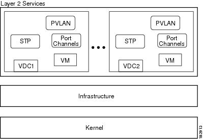
Virtualization Support for MST
The system provides support for virtual device contexts (VDCs), and each VDC runs a separate STP.
You can run Rapid PVST+ in one VDC and run MST in another VDC as shown in this figure. Each VDC will have its own MST. Ensure that you are in the correct VDC.
For example, VDC1 can run MST, VDC2 can run Rapid PVST+, and VDC 3 can run MST.
(注) |
MSTs in different VDCs are distinct, so you must perform MST region configuration for each VDC. |
(注) |
See the 『Cisco Nexus 7000 Series NX-OS Virtual Device Context Configuration Guide』, for complete information on VDCs and assigning resources. |
Licensing Requirements for MST
The following table shows the licensing requirements for this feature:
However, using VDCs requires an Advanced Services license.
Prerequisites for MST
MST has the following prerequisites:
Guidelines and Limitations for Configuring MST
(注) |
When you change the VLAN-to-MSTI mapping, the system reconverges MST. |
MST has the following configuration guidelines and limitations:
- You must enable MST; Rapid PVST+ is the default spanning tree mode.
- You can assign a VLAN to only one MST instance at a time.
- You cannot map VLANs 3968 to 4047 or 4094 to an MST instance. These VLANs are reserved for internal use by the device.
- You can have up to 65 MST instances on one device.
- The maximum number of VLANs and ports is 75,000.
- By default, all VLANs are mapped to MSTI 0 or the IST.
- When you are working with private VLANs on the system, ensure that all secondary VLANs are mapped to the same MSTI as the primary VLAN.
- You can load balance only within the MST region.
- Ensure that trunks carry all of the VLANs that are mapped to an MSTI or exclude all those VLANs that are mapped to an MSTI.
- Always leave STP enabled.
- Do not change timers because you can adversely affect your network stability.
- Keep user traffic off the management VLAN; keep the management VLAN separate from user data.
- Choose the distribution and core layers as the location of the primary and secondary root switches.
- Port channeling—The port channel bundle is considered as a single port. The port cost is the aggregation of all the configured port costs assigned to that channel.
- When you map a VLAN to an MSTI, the system automatically removes that VLAN from its previous MSTI.
- You can map any number of VLANs to an MSTI.
- All MST boundary ports must be forwarding for load balancing between Rapid PVST+ and an MST cloud or between a PVST+ and an MST cloud. The CIST regional root of the MST cloud must be the root of the CST. If the MST cloud consists of multiple MST regions, one of the MST regions must contain the CST root and all of the other MST regions must have a better path to the root contained within the MST cloud than a path through the Rapid PVST+ or PVST+ cloud.
- Do not partition the network into a large number of regions. However, if this situation is unavoidable, we recommend that you partition the switched LAN into smaller LANs interconnected by non-Layer 2 devices.
- When you work with private VLANs, enter the private-vlan synchronize command to map the secondary VLANs to the same MST instance as the primary VLAN.
-
When you are in the MST configuration submode, the following guidelines apply:
- Each command reference line creates its pending regional configuration.
- The pending region configuration starts with the current region configuration.
- To leave the MST configuration submode without committing any changes, enter the abort command.
- To leave the MST configuration submode and commit all the changes that you made before you left the submode, enter the exit or end commands, or press Ctrl + Z.
(注) |
The software supports full nondisruptive upgrades for MST. See 『Cisco Nexus 7000 Series NX-OS High Availability and Redundancy Guide』, for complete information about nondisruptive upgrades. |
MST のデフォルト設定
Configuring MST
(注) |
If you are familiar with the Cisco IOS CLI, be aware that the Cisco software commands for this feature might differ from the Cisco IOS commands that you would use. |
- MST のイネーブル化(CLI バージョン)
- MST コンフィギュレーション モードの開始
- MST の名前の指定
- MST 設定のリビジョン番号の指定
- MST 領域での設定の指定
- VLAN と MST インスタンスのマッピングおよびマッピング解除(CLI バージョン)
- プライベート VLAN でセカンダリ VLAN をプライマリ VLAN として同じ MSTI にマッピングするには
- ルート ブリッジの設定
- MST セカンダリ ルート ブリッジの設定
- MST スイッチ プライオリティの設定
- MST ポート プライオリティの設定
- MST ポート コストの設定
- MST hello タイムの設定
- MST 転送遅延時間の設定
- MST 最大エージング タイムの設定
- MST 最大ホップ カウントの設定
- 先行標準 MSTP メッセージを事前に送信するインターフェイスの設定(CLI バージョン)
- MST のリンク タイプの指定(CLI バージョン)
- MST 用のプロトコルの再初期化
MST のイネーブル化(CLI バージョン)
MST をイネーブルにできます。デフォルトは、Rapid PVST+ です。
同じ VDC 上で MST と Rapid PVST+ を同時に実行することはできません。
(注) |
スパニングツリー モードを変更すると、すべてのスパニングツリー インスタンスが前のモードで停止して新規モードで再開されるため、トラフィックが中断されます。 |
正しい VDC を開始していること(または switchto vdc コマンドを入力済みであること)を確認してください。
1. config t
2. 次のいずれかのコマンドを入力します。
3. exit
4. (任意) show running-config spanning-tree all
5. (任意) copy running-config startup-config
手順の詳細
| コマンドまたはアクション | 目的 | |||||||
|---|---|---|---|---|---|---|---|---|
| ステップ 1 | config t 例: switch# config t switch(config)# |
コンフィギュレーション モードを開始します。 |
||||||
| ステップ 2 | 次のいずれかのコマンドを入力します。
例: switch(config)# spanning-tree mode mst |
|||||||
| ステップ 3 | exit 例: switch(config)# exit switch# |
コンフィギュレーション モードを終了します。 |
||||||
| ステップ 4 | show running-config spanning-tree all 例: switch# show running-config spanning-tree all |
(任意) 現在稼働している STP コンフィギュレーションを表示します。 |
||||||
| ステップ 5 | copy running-config startup-config 例: switch# copy running-config startup-config |
(任意) 実行コンフィギュレーションを、スタートアップ コンフィギュレーションにコピーします。 |
次に、デバイス上で MST をイネーブルにする例を示します。
switch# config t switch(config)# spanning-tree mode mst switch(config)# exit switch#
MST コンフィギュレーション モードの開始
デバイスに MST 名、VLAN/インスタンス マッピング、および MST リビジョン番号を設定するには、MST コンフィギュレーション モードを開始します。
複数のデバイスが同じ MST 領域内にある場合は、これらのデバイスの MST 名、VLAN/インスタンス マッピング、および MST リビジョン番号を同一にする必要があります。
(注) |
各コマンド参照行により、MST コンフィギュレーション モードで保留中の領域設定が作成されます。 さたに、保留中の領域設定により、現在の領域設定が開始されます。 |
正しい VDC を開始していること(または switchto vdc コマンドを入力済みであること)を確認してください。
1. config t
2. 次のいずれかのコマンドを入力します。
3. 次のいずれかのコマンドを入力します。
4. (任意) copy running-config startup-config
手順の詳細
| コマンドまたはアクション | 目的 | |||||||
|---|---|---|---|---|---|---|---|---|
| ステップ 1 | config t 例: switch# config t switch(config)# |
コンフィギュレーション モードを開始します。 |
||||||
| ステップ 2 | 次のいずれかのコマンドを入力します。
例: switch(config)# spanning-tree mst configuration switch(config-mst)# |
|||||||
| ステップ 3 | 次のいずれかのコマンドを入力します。
例: switch(config-mst)# exit switch(config)# |
|||||||
| ステップ 4 | copy running-config startup-config 例: switch(config)# copy running-config startup-config |
(任意) 実行コンフィギュレーションを、スタートアップ コンフィギュレーションにコピーします。 |
次に、デバイスで MST コンフィギュレーション サブモードを開始する例を示します。
switch# spanning-tree mst configuration switch(config-mst)#
MST の名前の指定
ブリッジに領域名を設定できます。 複数のブリッジが同じ MST 領域内にある場合は、これらのブリッジの MST 名、VLAN/インスタンス マッピング、および MST リビジョン番号を同一にする必要があります。
正しい VDC を開始していること(または switchto vdc コマンドを入力済みであること)を確認してください。
1. config t
2. spanning-tree mst configuration
3. name name
4. 次のいずれかのコマンドを入力します。
5. (任意) show spanning-tree mst
6. (任意) copy running-config startup-config
手順の詳細
| コマンドまたはアクション | 目的 | |||||||
|---|---|---|---|---|---|---|---|---|
| ステップ 1 | config t 例: switch# config t switch(config)# |
コンフィギュレーション モードを開始します。 |
||||||
| ステップ 2 | spanning-tree mst configuration 例: switch(config)# spanning-tree mst configuration switch(config-mst)# |
MST コンフィギュレーション サブモードを開始します。 |
||||||
| ステップ 3 | name name 例: switch(config-mst)# name accounting |
MST 領域の名前を指定します。 name ストリングには最大 32 文字まで使用でき、大文字と小文字が区別されます。 デフォルトは空の文字列です。 |
||||||
| ステップ 4 | 次のいずれかのコマンドを入力します。
例: switch(config-mst)# exit switch(config)# |
|||||||
| ステップ 5 | show spanning-tree mst 例: switch# show spanning-tree mst |
(任意) MST 設定を表示します。 |
||||||
| ステップ 6 | copy running-config startup-config 例: switch(config)# copy running-config startup-config |
(任意) 実行コンフィギュレーションを、スタートアップ コンフィギュレーションにコピーします。 |
次の例は、MST 領域の名前の設定方法を示しています。
switch# spanning-tree mst configuration switch(config-mst)# name accounting switch(config-mst)#
MST 設定のリビジョン番号の指定
リビジョン番号は、ブリッジ上に設定します。 複数のブリッジが同じ MST 領域内にある場合は、これらのブリッジの MST 名、VLAN/インスタンス マッピング、および MST リビジョン番号を同一にする必要があります。
正しい VDC を開始していること(または switchto vdc コマンドを入力済みであること)を確認してください。
1. config t
2. spanning-tree mst configuration
3. revision version
4. 次のいずれかのコマンドを入力します。
5. (任意) show spanning-tree mst
6. (任意) copy running-config startup-config
手順の詳細
| コマンドまたはアクション | 目的 | |||||||
|---|---|---|---|---|---|---|---|---|
| ステップ 1 | config t 例: switch# config t switch(config)# |
コンフィギュレーション モードを開始します。 |
||||||
| ステップ 2 | spanning-tree mst configuration 例: switch(config)# spanning-tree mst configuration switch(config-mst)# |
MST コンフィギュレーション サブモードを開始します。 |
||||||
| ステップ 3 | revision version 例: switch(config-mst)# revision 5 |
MST 領域のリビジョン番号を指定します。 範囲は 0 ~ 65535 で、デフォルト値は 0 です。 |
||||||
| ステップ 4 | 次のいずれかのコマンドを入力します。
例: switch(config-mst)# exit switch(config)# |
|||||||
| ステップ 5 | show spanning-tree mst 例: switch# show spanning-tree mst |
(任意) MST 設定を表示します。 |
||||||
| ステップ 6 | copy running-config startup-config 例: switch(config)# copy running-config startup-config |
(任意) 実行コンフィギュレーションを、スタートアップ コンフィギュレーションにコピーします。 |
次に、MSTI 領域のリビジョン番号を 5 に設定する例を示します。
switch# spanning-tree mst configuration switch(config-mst)# revision 5 switch(config-mst)#
MST 領域での設定の指定
2 台以上のデバイスを同一 MST 領域内に存在させるには、同じ VLAN からインスタンスへのマッピング、同じ構成リビジョン番号、および同じ MST の名前が設定されている必要があります。
領域には、同じ MST 設定の 1 つのメンバーまたは複数のメンバーを存在させることができます。各メンバーでは、IEEE 802.1w RSTP BPDU を処理できる必要があります。 ネットワーク内の MST 領域には、数の制限はありませんが、各領域では、最大 65 までのインスタンスをサポートできます。 VLAN は、一度に 1 つの MST インスタンスに対してのみ割り当てることができます。
正しい VDC を開始していること(または switchto vdc コマンドを入力済みであること)を確認してください。
1. config t
2. spanning-tree mst configuration
3. instance instance-id vlan vlan-range
4. name name
5. revision version
6. 次のいずれかのコマンドを入力します。
7. show spanning-tree mst
8. copy running-config startup-config
手順の詳細
| コマンドまたはアクション | 目的 | |||||||
|---|---|---|---|---|---|---|---|---|
| ステップ 1 | config t 例: switch# config t switch(config)# |
コンフィギュレーション モードを開始します。 |
||||||
| ステップ 2 | spanning-tree mst configuration 例: switch(config)# spanning-tree mst configuration switch(config-mst)# |
MST コンフィギュレーション サブモードを開始します。 |
||||||
| ステップ 3 | instance instance-id vlan vlan-range 例: switch(config-mst)# instance 1 vlan 10-20 |
VLAN を MST インスタンスにマッピングする手順は、次のとおりです。
VLAN 範囲を指定する場合は、ハイフンを使用します。たとえば、instance 1 vlan 1-63 とコマンドを入力すると、MST インスタンス 1 に VLAN 1 ~ 63 がマッピングされます。 複数の VLAN を指定する場合はカンマで区切ります。たとえば、instance 1 vlan 10, 20, 30 と指定すると、MST インスタンス 1 に VLAN 10、20、および 30 がマッピングされます。 |
||||||
| ステップ 4 | name name 例: switch(config-mst)# name region1 |
インスタンス名を指定します。 name ストリングには最大 32 文字まで使用でき、大文字と小文字が区別されます。 |
||||||
| ステップ 5 | revision version 例: switch(config-mst)# revision 1 |
設定リビジョン番号を指定します。 指定できる範囲は 0 ~ 65535 です。 |
||||||
| ステップ 6 | 次のいずれかのコマンドを入力します。
例: switch(config-mst)# exit switch(config)# |
|||||||
| ステップ 7 | show spanning-tree mst 例: switch# show spanning-tree mst |
(任意)MST 設定を表示します。 |
||||||
| ステップ 8 | copy running-config startup-config 例: switch(config)# copy running-config startup-config |
(任意)実行コンフィギュレーションをスタートアップ コンフィギュレーションにコピーします。
|
次の例では、MST コンフィギュレーション モードを開始して VLAN 10 ~ 20 を MST インスタンス 1 にマッピングし、リージョンに region1 と名前を付けて、コンフィギュレーション リビジョンを 1 に設定します。その後、変更確認前の設定を表示して変更を適用し、グローバル コンフィギュレーション モードに戻る方法を示します。
switch# spanning-tree mst configuration switch(config-mst)# instance 1 vlan 10-20 switch(config-mst)# name region1 switch(config-mst)# revision 1 switch(config-mst#) show pending Pending MST configuration Name [region1] Revision 1 Instances configured 2 Instance Vlans Mapped -------- --------------------- 0 1-9,21-4094 1 10-20 ------------------------------- switch(config-mst)# exit switch(config)#
VLAN と MST インスタンスのマッピングおよびマッピング解除(CLI バージョン)
複数のブリッジが同じ MST 領域内にある場合は、これらのブリッジの MST 名、VLAN/インスタンス マッピング、および MST リビジョン番号を同一にする必要があります。
VLAN 3968 ~ 4047 または VLAN 4094 は MST インスタンスにマッピングできません。 これらの VLAN は、デバイスによる内部使用のために予約されています。
(注) |
VLAN/MSTI マッピングを変更すると、MST が再コンバージェンスされます。 |
(注) |
MSTI はディセーブルにできません。 |
正しい VDC を開始していること(または switchto vdc コマンドを入力済みであること)を確認してください。
1. config t
2. spanning-tree mst configuration
3. 次のいずれかのコマンドを入力します。
4. 次のいずれかのコマンドを入力します。
5. (任意) show spanning-tree mst
6. (任意) copy running-config startup-config
手順の詳細
| コマンドまたはアクション | 目的 | |||||||
|---|---|---|---|---|---|---|---|---|
| ステップ 1 | config t 例: switch# config t switch(config)# |
コンフィギュレーション モードを開始します。 |
||||||
| ステップ 2 | spanning-tree mst configuration 例: switch(config)# spanning-tree mst configuration switch(config-mst)# |
MST コンフィギュレーション サブモードを開始します。 |
||||||
| ステップ 3 | 次のいずれかのコマンドを入力します。
例: switch(config-mst)# instance 3 vlan 200 |
|||||||
| ステップ 4 | 次のいずれかのコマンドを入力します。
例: switch(config-mst)# exit switch(config)# |
|||||||
| ステップ 5 | show spanning-tree mst 例: switch# show spanning-tree mst |
(任意) MST 設定を表示します。 |
||||||
| ステップ 6 | copy running-config startup-config 例: switch(config)# copy running-config startup-config |
(任意) 実行コンフィギュレーションを、スタートアップ コンフィギュレーションにコピーします。 |
次の例は、VLAN 200 を MSTI 3 にマッピングする方法を示しています。
switch# config t switch(config)# spanning-tree mst configuration switch(config-mst)# instance 3 vlan 200 switch(config-mst)#
プライベート VLAN でセカンダリ VLAN をプライマリ VLAN として同じ MSTI にマッピングするには
システムのプライベート VLAN で作業しているときは、関連プライマリ VLAN と同じ MSTI にすべてのセカンダリ VLAN を配置する必要があります。 この同期を自動的に実現するには、private-vlan synchronize コマンドを入力します。
正しい VDC を開始していること(または switchto vdc コマンドを入力済みであること)を確認してください。
1. config t
2. spanning-tree mst configuration
3. private-vlan synchronize
4. 次のいずれかのコマンドを入力します。
5. (任意) show spanning-tree mst
6. (任意) copy running-config startup-config
手順の詳細
| コマンドまたはアクション | 目的 | |||||||
|---|---|---|---|---|---|---|---|---|
| ステップ 1 | config t 例: switch# config t switch(config)# |
コンフィギュレーション モードを開始します。 |
||||||
| ステップ 2 | spanning-tree mst configuration 例: switch(config)# spanning-tree mst configuration switch(config-mst)# |
MST コンフィギュレーション サブモードを開始します。 |
||||||
| ステップ 3 | private-vlan synchronize 例: g-mst)# private-vlan synchronize |
すべてのプライベート VLAN について、関連プライマリ VLAN と同じ MSTI にすべてのセカンダリ VLAN を自動的にマッピングします。 |
||||||
| ステップ 4 | 次のいずれかのコマンドを入力します。
例: switch(config-mst)# exit switch(config)# |
|||||||
| ステップ 5 | show spanning-tree mst 例: switch# show spanning-tree mst |
(任意) MST 設定を表示します。 |
||||||
| ステップ 6 | copy running-config startup-config 例: switch(config)# copy running-config startup-config |
(任意) 実行コンフィギュレーションを、スタートアップ コンフィギュレーションにコピーします。 |
次の例は、すべてのプライベート VLAN と同じ MSTI および関連プライマリ VLAN にすべてのセカンダリ VLAN を自動的にマッピングする方法を示しています。
switch# config t switch(conf9g)# spanning-tree mst configuration switch(config-mst)# private-vlan synchronize switch(config-mst)#
ルート ブリッジの設定
MST ルート ブリッジになるデバイスを設定できます。
ルート ブリッジになるために必要な値が 4096 より小さい場合は、spanning-tree vlan vlan_ID primary root コマンドはエラーになります。 ソフトウェアでブリッジ プライオリティをそれ以上低くできない場合、デバイスは次のメッセージを返します。
Error: Failed to set root bridge for VLAN 1 It may be possible to make the bridge root by setting the priority for some (or all) of these instances to zero.
(注) |
各 MSTI のルート ブリッジは、バックボーンまたはディストリビューション デバイスである必要があります。 アクセス デバイスは、スパニングツリーのプライマリ ルート ブリッジとして設定しないでください。 |
レイヤ 2 ネットワークの直径(レイヤ 2 ネットワーク上の任意の 2 台のエンド ステーション間における最大レイヤ 2 ホップ カウント)を指定するには、MSTI 0(IST)専用の diameter キーワードを入力します。 ネットワーク直径を指定すると、デバイスは、その直径のネットワークで最適な hello タイム、転送遅延時間、最大エージング タイムを自動的に設定し、これによって収束時間が大幅に短縮されます。 hello キーワードを入力すると、自動的に計算された hello タイムを上書きできます。
(注) |
ルート ブリッジとして設定されているデバイスでは、hello タイム、転送遅延時間、最大エージング タイムは手動で設定(spanning-tree mst hello-time、spanning-tree mst forward-time、spanning-tree mst max-age の各グローバル コンフィギュレーション コマンドを使用)しないでください。 |
正しい VDC を開始していること(または switchto vdc コマンドを入力済みであること)を確認してください。
1. config t
2. 次のいずれかのコマンドを入力します。
3. 次のいずれかのコマンドを入力します。
4. (任意) show spanning-tree mst
5. (任意) copy running-config startup-config
手順の詳細
| コマンドまたはアクション | 目的 | |||||||
|---|---|---|---|---|---|---|---|---|
| ステップ 1 | config t 例: switch# config t switch(config)# |
コンフィギュレーション モードを開始します。 |
||||||
| ステップ 2 | 次のいずれかのコマンドを入力します。
例: switch(config)# spanning-tree mst 5 root primary |
|||||||
| ステップ 3 | 次のいずれかのコマンドを入力します。
例: switch(config)# exit switch# |
|||||||
| ステップ 4 | show spanning-tree mst 例: switch# show spanning-tree mst |
(任意) MST 設定を表示します。 |
||||||
| ステップ 5 | copy running-config startup-config 例: switch(config)# copy running-config startup-config |
(任意) 実行コンフィギュレーションを、スタートアップ コンフィギュレーションにコピーします。 |
次に、デバイスを MSTI 5 のルート スイッチに設定する例を示します。
switch# config t switch(config)# spanning-tree mst 5 root primary switch(config)#
MST セカンダリ ルート ブリッジの設定
複数のバックアップ ルート ブリッジを設定するには、複数のデバイスでこのコマンドを使用します。 spanning-tree mst root primary グローバル コンフィギュレーション コマンドでプライマリ ルート ブリッジを設定したときに使用したのと同じネットワーク直径と hello タイムの値を入力します。
正しい VDC を開始していること(または switchto vdc コマンドを入力済みであること)を確認してください。
1. config t
2. 次のいずれかのコマンドを入力します。
3. exit
4. (任意) show spanning-tree mst
5. (任意) copy running-config startup-config
手順の詳細
| コマンドまたはアクション | 目的 | |||||||
|---|---|---|---|---|---|---|---|---|
| ステップ 1 | config t 例: switch# config t switch(config)# |
コンフィギュレーション モードを開始します。 |
||||||
| ステップ 2 | 次のいずれかのコマンドを入力します。
例: switch(config)# spanning-tree mst 5 root secondary |
|||||||
| ステップ 3 | exit 例: switch# exit switch(config)# |
コンフィギュレーション モードを終了します。 |
||||||
| ステップ 4 | show spanning-tree mst 例: switch# show spanning-tree mst |
(任意) MST 設定を表示します。 |
||||||
| ステップ 5 | copy running-config startup-config 例: switch(config)# copy running-config startup-config |
(任意) 実行コンフィギュレーションを、スタートアップ コンフィギュレーションにコピーします。 |
次に、デバイスを MSTI 5 のセカンダリ ルートスイッチに設定する例を示します。
switch# config t switch(config)# spanning-tree mst 5 root secondary switch(config)#
MST スイッチ プライオリティの設定
MST インスタンスのスイッチ プライオリティを設定し、指定デバイスがルート ブリッジとして選択される可能性を高めることができます。
(注) |
spanning-tree mst priority コマンドを使用するときは注意してください。 ほとんどの場合、スイッチのプライオリティを変更するには、spanning-tree mst root primary および spanning-tree mst root secondary のグローバル コンフィギュレーション コマンドの使用を推奨します。 |
正しい VDC を開始していること(または switchto vdc コマンドを入力済みであること)を確認してください。
1. config t
2. spanning-tree mst instance-id priority priority-value
3. exit
4. (任意) show spanning-tree mst
5. (任意) copy running-config startup-config
手順の詳細
| コマンドまたはアクション | 目的 | |
|---|---|---|
| ステップ 1 | config t 例: switch# config t switch(config)# |
コンフィギュレーション モードを開始します。 |
| ステップ 2 | spanning-tree mst instance-id priority priority-value 例: switch(config)# spanning-tree mst 5 priority 4096 |
次のようにデバイス プライオリティを設定します。
|
| ステップ 3 | exit 例: switch(config)# exit switch# |
コンフィギュレーション モードを終了します。 |
| ステップ 4 | show spanning-tree mst 例: switch# show spanning-tree mst |
(任意) MST 設定を表示します。 |
| ステップ 5 | copy running-config startup-config 例: switch(config)# copy running-config startup-config |
(任意) 実行コンフィギュレーションを、スタートアップ コンフィギュレーションにコピーします。 |
次の例は、MSTI 5 のブリッジのプライオリティを 4096 に設定する方法を示しています。
switch# config t switch(config)# spanning-tree mst 5 priority 4096 switch(config)#
MST ポート プライオリティの設定
ループが発生する場合、MST は、フォワーディング ステートにするインターフェイスを選択するとき、ポート プライオリティを使用します。 最初に選択させるインターフェイスには低いプライオリティの値を割り当て、最後に選択させるインターフェイスには高いプライオリティの値を割り当てることができます。 すべてのインターフェイスのプライオリティ値が同一である場合、MST はインターフェイス番号が最も低いインターフェイスをフォワーディング ステートにして、その他のインターフェイスをブロックします。
正しい VDC を開始していること(または switchto vdc コマンドを入力済みであること)を確認してください。
1. config t
2. interface {{type slot/port} | {port-channel number}}
3. spanning-tree mst instance-id port-priority priority
4. exit
5. (任意) show spanning-tree mst
6. (任意) copy running-config startup-config
手順の詳細
| コマンドまたはアクション | 目的 | |
|---|---|---|
| ステップ 1 | config t 例: switch# config t switch(config)# |
コンフィギュレーション モードを開始します。 |
| ステップ 2 | interface {{type slot/port} | {port-channel number}} 例: switch(config)# interface ethernet 3/1 switch(config-if)# |
設定するインターフェイスを指定し、インターフェイス コンフィギュレーション モードを開始します。 |
| ステップ 3 | spanning-tree mst instance-id port-priority priority 例: switch(config-if)# spanning-tree mst 3 port-priority 64 |
次のように、ポートのプライオリティを設定します。 |
| ステップ 4 | exit 例: switch(config-if)# exit switch(config)# |
インターフェイス モードを終了します。 |
| ステップ 5 | show spanning-tree mst 例: switch# show spanning-tree mst |
(任意) MST 設定を表示します。 |
| ステップ 6 | copy running-config startup-config 例: switch(config)# copy running-config startup-config |
(任意) 実行コンフィギュレーションを、スタートアップ コンフィギュレーションにコピーします。 |
次の例は、イーサネット ポート 3/1 で MSTI 3 の MST インターフェイス ポート プライオリティを 64 に設定する方法を示しています。
switch# config t switch(config)# interface ethernet 3/1 switch(config-if)# spanning-tree mst 3 port-priority 64 switch(config-if)# exit switch(config)#
MST ポート コストの設定
MST ポート コストのデフォルト値は、インターフェイスのメディア速度から抽出されます。 ループが発生した場合、MST は、コストを使用して、フォワーディング ステートにするインターフェイスを選択します。 最初に選択させるインターフェイスには小さいコストの値を割り当て、最後に選択させるインターフェイスの値には大きいコストを割り当てることができます。 すべてのインターフェイスのコスト値が同一である場合、MST はインターフェイス番号が最も低いインターフェイスをフォワーディング ステートにして、その他のインターフェイスをブロックします。
(注) |
MST はロング パスコスト計算方式を使用します。 |
正しい VDC を開始していること(または switchto vdc コマンドを入力済みであること)を確認してください。
1. config t
2. interface {{type slot/port} | {port-channel number}}
3. spanning-tree mst instance-id cost {cost | auto}
4. exit
5. (任意) show spanning-tree mst
6. (任意) copy running-config startup-config
手順の詳細
| コマンドまたはアクション | 目的 | |
|---|---|---|
| ステップ 1 | config t 例: switch# config t switch(config)# |
コンフィギュレーション モードを開始します。 |
| ステップ 2 | interface {{type slot/port} | {port-channel number}} 例: switch# config t switch(config)# interface ethernet 3/1 switch(config-if)# |
設定するインターフェイスを指定し、インターフェイス コンフィギュレーション モードを開始します。 |
| ステップ 3 | spanning-tree mst instance-id cost {cost | auto} 例: switch(config-if)# spanning-tree mst 4 cost 17031970 |
コストを設定します。 ループが発生する場合、MST は、フォワーディング ステートにするインターフェイスを選択するとき、パス コストを使用します。 パス コストが小さいほど、送信速度が速いことを示します。 |
| ステップ 4 | exit 例: switch(config-if)# exit switch(config)# |
インターフェイス モードを終了します。 |
| ステップ 5 | show spanning-tree mst 例: switch# show spanning-tree mst |
(任意) MST 設定を表示します。 |
| ステップ 6 | copy running-config startup-config 例: switch(config)# copy running-config startup-config |
(任意) 実行コンフィギュレーションを、スタートアップ コンフィギュレーションにコピーします。 |
次の例は、イーサネット ポート 3/1 で MSTI 4 の MST インターフェイス ポート コストを設定する方法を示しています。
switch# config t switch(config)# interface ethernet 3/1 switch(config-if)# spanning-tree mst 4 cost 17031970 switch(config-if)# exit switch(config)#
MST hello タイムの設定
デバイス上のすべてのインスタンスに対してルート ブリッジが作成する設定メッセージの間隔を設定するには、hello タイムを変更します。
(注) |
spanning-tree mst hello-time コマンドを使用するときは注意してください。 ほとんどの場合、hello タイムを変更するには、spanning-tree mst instance-id root primary および spanning-tree mst instance-id root secondary のグローバル コンフィギュレーション コマンドの使用を推奨します。 |
正しい VDC を開始していること(または switchto vdc コマンドを入力済みであること)を確認してください。
1. config t
2. spanning-tree mst hello-time seconds
3. exit
4. (任意) show spanning-tree mst
5. (任意) copy running-config startup-config
手順の詳細
| コマンドまたはアクション | 目的 | |
|---|---|---|
| ステップ 1 | config t 例: switch# config t switch(config)# |
コンフィギュレーション モードを開始します。 |
| ステップ 2 | spanning-tree mst hello-time seconds 例: switch(config)# spanning-tree mst hello-time 1 |
すべての MST インスタンスについて、hello タイムを設定します。 hello タイムは、ルート ブリッジが設定メッセージを生成する時間です。 これらのメッセージは、デバイスが動作していることを示します。 seconds の範囲は 1 ~ 10 で、デフォルトは 2 秒です。 |
| ステップ 3 | exit 例: switch(config)# exit switch# |
コンフィギュレーション モードを終了します。 |
| ステップ 4 | show spanning-tree mst 例: switch# show spanning-tree mst |
(任意) MST 設定を表示します。 |
| ステップ 5 | copy running-config startup-config 例: switch(config)# copy running-config startup-config |
(任意) 実行コンフィギュレーションを、スタートアップ コンフィギュレーションにコピーします。 |
次に、デバイスの hello タイムを 1 秒に設定する例を示します。
switch# config t switch(config)# spanning-tree mst hello-time 1 switch(config)#
MST 転送遅延時間の設定
デバイスのすべての MST インスタンスの転送遅延時間を 1 つのコマンドで設定できます。
正しい VDC を開始していること(または switchto vdcswitchto vdc コマンドを入力済みであること)を確認してください。
1. config t
2. spanning-tree mst forward-time seconds
3. exit
4. (任意) show spanning-tree mst
5. (任意) copy running-config startup-config
手順の詳細
| コマンドまたはアクション | 目的 | |
|---|---|---|
| ステップ 1 | config t 例: switch# config t switch(config)# |
コンフィギュレーション モードを開始します。 |
| ステップ 2 | spanning-tree mst forward-time seconds 例: switch(config)# spanning-tree mst forward-time 10 |
すべての MST インスタンスについて、転送時間を設定します。 転送遅延は、スパニングツリー ブロッキング ステートとラーニング ステートからフォワーディング ステートに変更する前に、ポートが待つ秒数です。 seconds の範囲は 4 ~ 30 で、デフォルトは 15 秒です。 |
| ステップ 3 | exit 例: switch(config)# exit switch# |
コンフィギュレーション モードを終了します。 |
| ステップ 4 | show spanning-tree mst 例: switch# show spanning-tree mst |
(任意) MST 設定を表示します。 |
| ステップ 5 | copy running-config startup-config 例: switch(config)# copy running-config startup-config |
(任意) 実行コンフィギュレーションを、スタートアップ コンフィギュレーションにコピーします。 |
次に、デバイスの転送遅延時間を 10 秒に設定する例を示します。
switch# config t switch(config)# spanning-time mst forward-time 10 switch(config)#
MST 最大エージング タイムの設定
デバイスのすべての MST インスタンスの最大エージング タイマーを 1 つのコマンドで設定できます(最大エージング タイムが適用されるのは IST のみです)。
最大エージング タイマーは、デバイスがスパニングツリー設定メッセージを受信せずに再設定を試行するまで待機する秒数です。
正しい VDC を開始していること(または switchto vdc コマンドを入力済みであること)を確認してください。
1. config t
2. spanning-tree mst max-age seconds
3. exit
4. (任意) show spanning-tree mst
5. (任意) copy running-config startup-config
手順の詳細
| コマンドまたはアクション | 目的 | |
|---|---|---|
| ステップ 1 | config t 例: switch# config t switch(config)# |
コンフィギュレーション モードを開始します。 |
| ステップ 2 | spanning-tree mst max-age seconds 例: switch(config)# spanning-tree mst max-age 40 |
すべての MST インスタンスについて、最大経過時間を設定します。 最大エージング タイムは、デバイスがスパニングツリー設定メッセージを受信せずに再設定を試行するまで待機する秒数です。 seconds の範囲は 6 ~ 40 で、デフォルトは 20 秒です。 |
| ステップ 3 | exit 例: switch(config)# exit switch# |
コンフィギュレーション モードを終了します。 |
| ステップ 4 | show spanning-tree mst 例: switch# show spanning-tree mst |
(任意) MST 設定を表示します。 |
| ステップ 5 | copy running-config startup-config 例: switch(config)# copy running-config startup-config |
(任意) 実行コンフィギュレーションを、スタートアップ コンフィギュレーションにコピーします。 |
次に、デバイスの最大エージング タイマーを 40 秒に設定する例を示します。
switch# config t switch(config)# spanning-tree mst max-age 40 switch(config)#
MST 最大ホップ カウントの設定
領域内の最大ホップを設定し、それをその領域内にある IST およびすべての MST インスタンスに適用できます。 MST では、IST リージョナル ルートへのパス コストと、IP の存続可能時間(TTL)メカニズムに類似したホップ カウント メカニズムが、使用されます。 ホップ カウントを設定すると、メッセージ エージ情報を設定するのと同様の結果が得られます(再構成の開始時期を決定します)。
正しい VDC を開始していること(または switchto vdc コマンドを入力済みであること)を確認してください。
1. config t
2. spanning-tree mst max-hops hop-count
3. exit
4. (任意) show spanning-tree mst
5. (任意) copy running-config startup-config
手順の詳細
| コマンドまたはアクション | 目的 | |
|---|---|---|
| ステップ 1 | config t 例: switch# config t switch(config)# |
コンフィギュレーション モードを開始します。 |
| ステップ 2 | spanning-tree mst max-hops hop-count 例: switch(config)# spanning-tree mst max-hops 40 |
BPDU が廃棄され、ポートに維持されていた情報が期限切れになるまでの、領域内でのホップ カウントを指定します。 hop-count の範囲は 1 ~ 255 で、デフォルト値は 20 ホップです。 |
| ステップ 3 | exit 例: switch(config-mst)# exit switch# |
コンフィギュレーション モードを終了します。 |
| ステップ 4 | show spanning-tree mst 例: switch# show spanning-tree mst |
(任意) MST 設定を表示します。 |
| ステップ 5 | copy running-config startup-config 例: switch(config)# copy running-config startup-config |
(任意) 実行コンフィギュレーションを、スタートアップ コンフィギュレーションにコピーします。 |
次の例は、最大ホップ カウントを 40 に設定する方法を示しています。
switch# config t switch(config)# spanning-tree mst max-hops 40 switch(config)#
先行標準 MSTP メッセージを事前に送信するインターフェイスの設定(CLI バージョン)
デフォルトで、MST を実行中のデバイス上のインターフェイスは、別のインターフェイスから先行標準 MSTP メッセージを受信したあと、標準ではなく先行標準の MSTP メッセージを送信します。 Cisco NX-OS Release 4.0(2) 以降のリリースでは、先行標準 MSTP メッセージを事前に送信するインターフェイスを設定できるようになりました。 つまり、指定されたインターフェイスは、先行標準 MSTP メッセージの受信を待機する必要がなく、この設定のインターフェイスは常に先行標準 MSTP メッセージを送信します。
正しい VDC を開始していること(または switchto vdc コマンドを入力済みであること)を確認してください。
1. config t
2. interface type slot/port
3. spanning-tree mst pre-standard [interface {{ type slot/port} | {port-channel number}}] [detail]
4. exit
5. (任意) show spanning-tree mst
6. (任意) copy running-config startup-config
手順の詳細
| コマンドまたはアクション | 目的 | |
|---|---|---|
| ステップ 1 | config t 例: switch# config t switch(config)# |
コンフィギュレーション モードを開始します。 |
| ステップ 2 | interface type slot/port 例: switch(config)# interface ethernet 1/4 switch(config-if)# |
設定するインターフェイスを指定します。インターフェイス コンフィギュレーション モードを開始します。 |
| ステップ 3 | spanning-tree mst pre-standard [interface {{ type slot/port} | {port-channel number}}] [detail] 例: switch(config-if)# spanning-tree mst pre-standard |
インターフェイスが MSTP 標準形式ではなく、先行標準形式の MSTP メッセージを常に送信するように指定します。 |
| ステップ 4 | exit 例: switch(config-if)# exit switch(config)# |
インターフェイス モードを終了します。 |
| ステップ 5 | show spanning-tree mst 例: switch# show spanning-tree mst |
(任意) MST 設定を表示します。 |
| ステップ 6 | copy running-config startup-config 例: switch(config)# copy running-config startup-config |
(任意) 実行コンフィギュレーションを、スタートアップ コンフィギュレーションにコピーします。 |
switch# config t
switch (config)# interface ethernet 1/4
switch(config-if)# spanning-tree mst pre-standard
switch(config-if)# exit
switch(config)#
MST のリンク タイプの指定(CLI バージョン)
Rapid の接続性(802.1w 規格)は、ポイントツーポイントのリンク上でのみ確立されます。 リンク タイプは、デフォルトでは、インターフェイスのデュプレックス モードから制御されます。 全二重ポートはポイントツーポイント接続であると見なされ、半二重ポートは共有接続であると見なされます。
リモート デバイスの単一ポートに、ポイントツーポイントで物理的に接続されている半二重リンクがある場合、リンク タイプのデフォルト設定を上書きして高速移行をイネーブルにできます。
リンクを共有に設定すると、STP は 802.1D にフォール バックします。
正しい VDC を開始していること(または switchto vdc コマンドを入力済みであること)を確認してください。
1. config t
2. interface type slot/port
3. spanning-tree link-type {auto | point-to-point | shared}
4. exit
5. (任意) show spanning-tree
6. (任意) copy running-config startup-config
手順の詳細
| コマンドまたはアクション | 目的 | |
|---|---|---|
| ステップ 1 | config t 例: switch# config t switch(config)# |
コンフィギュレーション モードを開始します。 |
| ステップ 2 | interface type slot/port 例: switch(config)# interface ethernet 1/4 switch(config-if)# |
設定するインターフェイスを指定します。インターフェイス コンフィギュレーション モードを開始します。 |
| ステップ 3 | spanning-tree link-type {auto | point-to-point | shared} 例: switch(config-if)# spanning-tree link-type point-to-point |
リンク タイプを、ポイントツーポイント インクまたは共有リンクに設定します。 デフォルト値はデバイス接続から読み取られ、半二重リンクは共有、全二重リンクはポイントツーポイントです。 リンク タイプが共有の場合、STP は 802.1D にフォール バックします。 デフォルトは auto で、インターフェイスのデュプレックス設定に基づいてリンク タイプが設定されます。 |
| ステップ 4 | exit 例: switch(config-if)# exit switch(config)# |
インターフェイス モードを終了します。 |
| ステップ 5 | show spanning-tree 例: switch# show spanning-tree |
(任意) STP コンフィギュレーションを表示します。 |
| ステップ 6 | copy running-config startup-config 例: switch(config)# copy running-config startup-config |
(任意) 実行コンフィギュレーションを、スタートアップ コンフィギュレーションにコピーします。 |
次の例は、リンク タイプをポイントツーポイント リンクとして設定する方法を示しています。
switch# config t
switch (config)# interface ethernet 1/4
switch(config-if)# spanning-tree link-type point-to-point
switch(config-if)# exit
switch(config)#
MST 用のプロトコルの再初期化
MST ブリッジでは、レガシー BPDU または異なる領域にアソシエートされている MST BPDU を受信するときに、ポートが領域の境界にあることを検出できます。 ただし、STP プロトコルを移行しても、レガシー デバイス(IEEE 802.1D だけが稼働するデバイス)が代表スイッチでないかぎり、レガシー デバイスがリンクから削除されたかどうかを判別することはできません。 デバイス全体で、または指定されたインターフェイスでプロトコル ネゴシエーションを再初期化する(ネイバー デバイスとの再ネゴシエーションを強制的に行う)には、次のコマンドを入力します。
正しい VDC を開始していること(または switchto vdc コマンドを入力済みであること)を確認してください。
1. clear spanning-tree detected-protocol [interface interface [interface-num | port-channel]]
手順の詳細
| コマンドまたはアクション | 目的 | |
|---|---|---|
| ステップ 1 | clear spanning-tree detected-protocol [interface interface [interface-num | port-channel]] 例: switch# clear spanning-tree detected-protocol |
デバイス全体または指定されたインターフェイスで、MST を再初期化します。 |
次に、スロット 2 のイーサネット インターフェイスのポート 8 で、MST を再初期化する例を示します。
switch# clear spanning-tree detected-protocol interface ethernet 2/8
MST 設定の確認
| コマンド |
目的 |
|---|---|
| show running-config spanning-tree [all] | STP 情報を表示します。 |
| show spanning-tree mst configuration |
MST 情報を表示します。 |
| show spanning-tree mst [detail] |
MST インスタンスの情報を表示します。 |
| show spanning-tree mst instance-id [detail] |
指定された MST インスタンスに関する情報を表示します。 |
| show spanning-tree mst instance-id interface {ethernet slot/port | port-channel channel-number} [detail] |
指定したインターフェイスおよびインスタンスの MST 情報を表示します。 |
| show spanning-tree summary |
STP の概要を表示します。 |
| show spanning-tree detail |
STP の詳細を表示します。 |
| show spanning-tree {vlan vlan-id | interface {[ethernet slot/port] | [port-channel channel-number]}} [detail] |
VLAN またはインターフェイス単位の STP 情報を表示します。 |
| show spanning-tree vlan vlan-id bridge |
STP ブリッジの情報を表示します。 |
これらのコマンド出力の詳細については、 『Cisco Nexus 7000 Series NX-OS Layer 2 Switching Command Reference』を参照してください。
MST 統計情報の表示およびクリア(CLI バージョン)
| コマンド |
目的 |
|---|---|
| clear spanning-tree counters [ interface type slot/port | vlanvlan-id] |
STP のカウンタをクリアします。 |
| show spanning-tree {vlan vlan-id | interface {[ethernet slot/port] | [port-channelchannel-number]}} detail |
送受信された BPDU などの STP 情報を、インターフェイスまたは VLAN 別に表示します。 |
MST の設定例
次に、MST を設定する例を示します。
switch# configure terminal
switch(config)# spanning-tree mode mst
switch(config)# spanning-tree port type edge bpduguard default
switch(config)# spanning-tree port type edge bpdufilter default
switch(config)# spanning-tree port type network default
switch(config)# spanning-tree mst 0-64 priority 24576
switch(config)# spanning-tree mst configuration
switch(config-mst)# name cisco_region_1
switch(config-mst)# revision 2
switch(config-mst)# instance 1 vlan 1-21
switch(config-mst)# instance 2 vlan 22-42
switch(config-mst)# instance 3 vlan 43-63
switch(config-mst)# instance 4 vlan 64-84
switch(config-mst)# instance 5 vlan 85-105
switch(config-mst)# instance 6 vlan 106-126
switch(config-mst)# instance 6 vlan 106-126
switch(config-mst)# instance 7 vlan 127-147
switch(config-mst)# instance 8 vlan 148-168
switch(config-mst)# instance 9 vlan 169-189
switch(config-mst)# instance 10 vlan 190-210
switch(config-mst)# instance 11 vlan 211-231
switch(config-mst)# instance 12 vlan 232-252
switch(config-mst)# instance 13 vlan 253-273
switch(config-mst)# instance 14 vlan 274-294
switch(config-mst)# instance 15 vlan 295-315
switch(config-mst)# instance 16 vlan 316-336
switch(config-mst)# instance 17 vlan 337-357
switch(config-mst)# instance 18 vlan 358-378
switch(config-mst)# instance 19 vlan 379-399
switch(config-mst)# instance 20 vlan 400-420
switch(config-mst)# instance 21 vlan 421-441
switch(config-mst)# instance 22 vlan 442-462
switch(config-mst)# instance 23 vlan 463-483
switch(config-mst)# instance 24 vlan 484-504
switch(config-mst)# instance 25 vlan 505-525
switch(config-mst)# instance 26 vlan 526-546
switch(config-mst)# instance 27 vlan 547-567
switch(config-mst)# instance 28 vlan 568-588
switch(config-mst)# instance 29 vlan 589-609
switch(config-mst)# instance 30 vlan 610-630
switch(config-mst)# instance 31 vlan 631-651
switch(config-mst)# instance 32 vlan 652-672
switch(config-mst)# instance 33 vlan 673-693
switch(config-mst)# instance 34 vlan 694-714
switch(config-mst)# instance 35 vlan 715-735
switch(config-mst)# instance 36 vlan 736-756
switch(config-mst)# instance 37 vlan 757-777
switch(config-mst)# instance 38 vlan 778-798
switch(config-mst)# instance 39 vlan 799-819
switch(config-mst)# instance 40 vlan 820-840
switch(config-mst)# instance 41 vlan 841-861
switch(config-mst)# instance 42 vlan 862-882
switch(config-mst)# instance 43 vlan 883-903
switch(config-mst)# instance 44 vlan 904-924
switch(config-mst)# instance 45 vlan 925-945
switch(config-mst)# instance 46 vlan 946-966
switch(config-mst)# instance 47 vlan 967-987
switch(config-mst)# instance 48 vlan 988-1008
switch(config-mst)# instance 49 vlan 1009-1029
switch(config-mst)# instance 50 vlan 1030-1050
switch(config-mst)# instance 51 vlan 1051-1071
switch(config-mst)# instance 52 vlan 1072-1092
switch(config-mst)# instance 53 vlan 1093-1113
switch(config-mst)# instance 54 vlan 1114-1134
switch(config-mst)# instance 55 vlan 1135-1155
switch(config-mst)# instance 56 vlan 1156-1176
switch(config-mst)# instance 57 vlan 1177-1197
switch(config-mst)# instance 58 vlan 1198-1218
switch(config-mst)# instance 59 vlan 1219-1239
switch(config-mst)# instance 60 vlan 1240-1260
switch(config-mst)# instance 61 vlan 1261-1281
switch(config-mst)# instance 62 vlan 1282-1302
switch(config-mst)# instance 63 vlan 1303-1323
switch(config-mst)# instance 64 vlan 1324-1344
switch(config-mst)# exit

switch(config)# interface ethernet 3/1
switch(config-if)# switchport
switch(config-if)# no shutdown
switch(config-if)# spanning-tree port type edge
switch(congig-if)# exit

switch(config)# interface ethernet 3/2
switch(config-if)# switchport
switch(config-if)# switchport mode trunk
switch(config-if)# no shutdown
switch(config-if)# spanning-tree guard root
switch(config-if)# exit
switch(config)#
MST の追加情報(CLI バージョン)
関連資料
| 関連項目 |
参照先 |
|---|---|
| コマンド リファレンス |
『Cisco Nexus 7000 Series NX-OS Layer 2 Switching Command Reference』 |
| レイヤ 2 インターフェイス |
『Cisco Nexus 7000 Series NX-OS Interfaces Configuration Guide, Release 6.x』 |
| NX-OS の基礎 |
『Cisco Nexus 7000 Series NX-OS Fundamentals Configuration Guide, Release 6.x』 |
| ハイ アベイラビリティ |
『Cisco Nexus 7000 Series NX-OS High Availability and Redundancy Guide』 |
| システム管理 |
『Cisco Nexus 7000 Series NX-OS System Management Configuration Guide, Release 6.x』 |
| 仮想デバイス コンテキスト(VDC) |
『Cisco Nexus 7000 Series NX-OS Virtual Device Context Configuration Guide』 |
| ライセンス |
|
| リリース ノート |
『Cisco Nexus 7000 Series NX-OS Release Notes, Release 6.x』 |
標準
| 標準 |
タイトル |
|---|---|
| IEEE 802.1Q-2006(旧称 IEEE 802.1s)、IEEE 802.1D-2004(旧称 IEEE 802.1w)、IEEE 802.1D、IEEE 802.1t |
— |
MIB
| MIB |
MIB のリンク |
|---|---|
| MIB を検索およびダウンロードするには、次の URL にアクセスしてください。http://www.cisco.com/public/sw-center/netmgmt/cmtk/mibs.shtml |
MST 設定の機能履歴(CLI バージョン)
| 機能名 |
リリース |
機能情報 |
|---|---|---|
| 変更なし |
4.2(1) |
-- |
| 変更なし |
4.1(2) |
-- |