Cisco Catalyst 6807-XL Switch Hardware Installation Guide(Cisco Catalyst 6807-XL スイッチハードウェア設置ガイド)
偏向のない言語
この製品のマニュアルセットは、偏向のない言語を使用するように配慮されています。このマニュアルセットでの偏向のない言語とは、年齢、障害、性別、人種的アイデンティティ、民族的アイデンティティ、性的指向、社会経済的地位、およびインターセクショナリティに基づく差別を意味しない言語として定義されています。製品ソフトウェアのユーザーインターフェイスにハードコードされている言語、RFP のドキュメントに基づいて使用されている言語、または参照されているサードパーティ製品で使用されている言語によりドキュメントに例外が存在する場合があります。シスコのインクルーシブランゲージに対する取り組みの詳細は、こちらをご覧ください。
翻訳について
このドキュメントは、米国シスコ発行ドキュメントの参考和訳です。リンク情報につきましては、日本語版掲載時点で、英語版にアップデートがあり、リンク先のページが移動/変更されている場合がありますことをご了承ください。あくまでも参考和訳となりますので、正式な内容については米国サイトのドキュメントを参照ください。
- Updated:
- 2017年6月27日
章のタイトル: トランシーバ、モジュール コネクタ、およびケーブルの仕様
目次
- トランシーバ、モジュール コネクタ、およびケーブルの仕様
- プラグイン可能なトランシーバ
- 1 GB トランシーバ
- 10 GB トランシーバ
- 40 GB トランシーバ
- WDM トランシーバ
- モジュール コネクタ
- RJ-45 コネクタ
- SC コネクタ
- LC コネクタ
- MTP-12 コネクタ
- 光ファイバ コネクタの清掃
- ガイドライン
- 光ファイバ コネクタを清掃する方法
- ケーブル仕様
- SFP モジュール ケーブル
- コンソール ケーブル
- DB-9 アダプタ(PC に接続)
- DB-25 アダプタ(端末との接続用)
- モデム アダプタ
- ロールオーバー ケーブルの識別
- ケーブルのピン割り当て
- モードコンディショニング パッチコード
- 例:パッチ コードの構成
- パッチ コードの取り付け
- DMD
プラグイン可能なトランシーバ
このセクションでは、スイッチ モジュールおよびスーパーバイザ エンジンに設置できる接続可能なトランシーバについて簡単に説明します。
 警告 |
この装置の設置、交換、または保守は、訓練を受けた相応の資格のある人が行ってください。 ステートメント 1030 |
警告 |
本製品の最終処分は、各国のすべての法律および規制に従って行ってください。 ステートメント 1040 |
警告 |
クラス I(CDRH)およびクラス 1M(IEC)レーザー製品です。 ステートメント 1055 |
警告 |
指定された制御、調整、または実行手順以外を使用した場合、危険な放射線に被曝する可能性があります。 ステートメント 1057 |
1 GB トランシーバ
| 1 GB トランシーバ タイプ |
サポートされるモジュール |
追加情報 |
|---|---|---|
| SFP |
|
 (注) |
特定の SFP トランシーバがサポートされるモジュールと互換性があるかどうかを判断するには、Cisco.com で入手できる「Cisco Gigabit Ethernet Transceiver Modules Compatibility Matrix(Cisco ギガビット イーサネット トランシーバ モジュール互換性マトリクス)」を参照してください。 |
10 GB トランシーバ
スイッチは 10 GB X2 および 10 Gb SFP+ トランシーバをサポートします。 次の表は、トランシーバがサポートするモジュールと、トランシーバ仕様のリンクの一覧を示しています。
| 10 GB トランシーバ タイプ |
サポートされるモジュール |
追加情報 |
|---|---|---|
| X2 トランシーバ |
|
|
| SFP+ トランシーバ |
|
|
特定の 10 GB トランシーバがサポートされるモジュールと互換性があるかどうかを判断するには、Cisco.com で入手できる「10-Gigabit Ethernet Transceiver Modules Compatibility Matrix(10 ギガビット イーサネット トランシーバ モジュール互換性マトリクス)」を参照してください。
40 GB トランシーバ
スイッチは 40 ギガビット イーサネット モジュール ポートに接続するホットスワップ可能な I/O デバイスである 40 ギガビット CFP トランシーバ モジュールをサポートします。 CFP トランシーバ モジュールは、光ネットワークとプラットフォームの電気回路を接続します。 次の表は、トランシーバがサポートするモジュールと、トランシーバ仕様のリンクの一覧を示しています。
| 40 GB トランシーバ タイプ |
サポートされるモジュール |
追加情報 |
|---|---|---|
| CFP トランシーバ |
|
(注) |
特定の 40 GB トランシーバがサポートされるモジュールと互換性があるかどうかを判断するには、Cisco.com で入手できる「Cisco 40-Gigabit Ethernet Transceiver Modules Compatibility Matrix(Cisco 40 ギガビット イーサネット トランシーバ モジュール互換性マトリクス)」を参照してください。 |
WDM トランシーバ
次の表は、WDM トランシーバをサポートするモジュール、該当の図と仕様表を示しています。
| WDM トランシーバ タイプ |
説明 |
サポートされるモジュール |
追加情報 |
||
|---|---|---|---|---|---|
| CWDM SFP |
CWDM SFP は、SFP 互換モジュールおよびスーパーバイザ エンジンに装着できるホットスワップ可能なトランシーバ コンポーネントです。 CWDM SFP トランシーバでは、LC 光コネクタを使用して、SMF 光ケーブルに接続します。 SMF 光ケーブルを使用して、CWDM SFP を CWDM Passive Optical System Optical Add/Drop Multiplexer(OADM)モジュールまたはマルチプレクサ/デマルチプレクサ プラグイン モジュールに接続できます。 |
|
|||
| DWDM SFP |
Cisco DWDM SFP は、ギガビット イーサネット SFP ポートまたはスロットに接続するホットスワップ可能な I/O トランシーバ モジュールです。 ITU 100-GHz 波長グリッドをサポートし、Cisco 100-GHz ONS 製品ファミリ向け波長計画に一致します。 40 の異なる SFP モデルを持つ固定波長 SFP です。 標準 SFP インターフェイスのネットワーク、デュアル LC/PC コネクタを使用します。
|
|
Cisco Dense Wavelength-Division Multiplexing Small Form-Factor Pluggable Module |
||
| DWDM SFP+ |
Cisco DWDM SFP+ トランシーバ モジュールは、ポートをネットワークとリンクするシスコ スイッチまたはルータのイーサネット SFP+ ポートに接続するホットスワップ可能な I/O デバイスです。 40 の非調整可能な ITU 100-GHz 波長をサポートします。 また、デジタル オプティカル モニタリング機能と、Cisco スイッチまたはルータでモジュールがシスコによって検証およびテストされている SFP+ モジュールかを判断するのに使用できる Cisco Quality identification(ID)機能をサポートしています。 |
|
|||
| DWDM X2 | Cisco DWDM X2 トランシーバは、ポートをネットワークにリンクするためにスイッチのイーサネット X2 ポートに接続されるホットスワップ可能な I/O モジュールです。 モジュールは Cisco ONS DWDM チャネル計画と互換性がある 32 の非調整 ITU 100-GHz 波長をサポートします。 Cisco DWDM X2 はデジタル オプティカル モニタリング機能をサポートします。 |
|
(注) |
特定の WDM トランシーバがサポートされるモジュールと互換性があるかどうかを判断するには、Cisco.com で入手できる「Cisco Gigabit Ethernet Transceiver Modules Compatibility Matrix(Cisco ギガビット イーサネット トランシーバ モジュール互換性マトリクス)」を参照してください。 |
モジュール コネクタ
このセクションでは、スイッチがサポートするモジュール コネクタについて簡単に説明します。
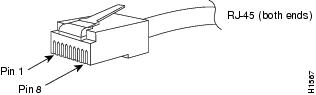
RJ-45 コネクタ
RJ-45 コネクタは、カテゴリ 3、5、5e、または 6 のホイル ツイストペア(FTP)またはシールドなしツイストペア ケーブル(UTP)ケーブルを使用して、モジュールのインターフェイス コネクタと外部ネットワークを接続する場合に使用されます。
 注意 |
カテゴリ 5e、カテゴリ 6、および カテゴリ 6a のケーブルは、誘電性の物質で構成されているため、静電気を大量に帯びる可能性があります。 常にケーブル(特に新規ケーブルの設置)を適切で安全な方法でアースできるようにしてから、モジュールに接続してください。 |
注意 |
GR-1089 の建物内雷サージ耐性要件に適合するためには、両端に適切なアースを施した FTP ケーブルを使用する必要があります。 |
SC コネクタ
SC コネクタは、光ファイバ モジュール ポートまたはトランシーバを外部の SMF または MMF ネットワークに接続するために使用されます。
警告 |
接続されていない光ファイバ ケーブルやコネクタからは目に見えないレーザー光が放射されている可能性があります。 レーザー光を直視したり、光学機器を使用して直接見たりしないでください。 ステートメント 1051 |
(注) |
接続する前に、光コネクタが汚れていないことを確認してください。 コネクタが汚れていると、光ファイバが損傷したり、データ エラーが発生することがあります。 |
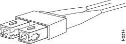
ネットワーク コネクタは必ずソケットに完全に差し込んでください。 確実な接続は、モジュールを長距離(2 km[1.24 マイル ])ネットワーク、またはモジュールを減衰が大きいと考えられるネットワークに接続する場合、特に重要になります。 LINK LED が点灯しない場合は、ネットワーク ケーブルのプラグを取り外してから、再度モジュール ソケットにしっかり差し込んでください。 プラグの前面プレート(光ファイバの開口部の周辺)に埃や皮脂がたまると大幅な減衰が生じて、光パワー レベルがしきい値を下回り、リンクを確立できなくなることがあります。
注意 |
コネクタの取り付けまたは取り外しを行うときは、コネクタ ハウジングを損傷したり、ファイバ終端の表面を傷付けないように十分に注意してください。 汚れを防ぐために、使用または接続していないコンポーネントには必ず保護カバーを取り付けてください。 コネクタを取り付ける前に、必ずコネクタを清掃してください。 |
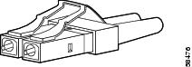
LC コネクタ
LC 光ファイバ コネクタは、高密度のファイバ接続を提供する小型フォーム ファクタ光ファイバ コネクタです。 LC コネクタは MMF または SMF ケーブルのどちらかとともに使用できます。 LC コネクタには、RJ-45 銅製コネクタと同様のラッチ クリップ機構が使用されています。
警告 |
接続されていない光ファイバ ケーブルやコネクタからは目に見えないレーザー光が放射されている可能性があります。 レーザー光を直視したり、光学機器を使用して直接見たりしないでください。 ステートメント 1051 |
(注) |
接続する前に、光コネクタが汚れていないことを確認してください。 コネクタが汚れていると、光ファイバが損傷したり、データ エラーが発生することがあります。 |
MTP-12 コネクタ
MTP コネクタは、SC シンプレックス コネクタと同様のフットプリントを持つ 12 光ファイバ コネクタです。 MTP コネクタは、TIA/EIA-604-5 接続互換性標準への準拠が指定されています。
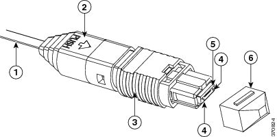
| 1 |
12 ファイバ リボン |
4 |
ガイド ピン |
| 2 |
ブート |
5 |
フェルール |
| 3 |
ハウジング アセンブリ |
6 |
ダスト キャップ |
光ファイバ コネクタの清掃
2 本の光ファイバを接続するには、光ファイバ コネクタを使用します。 通信システムでこれらのコネクタを使用する場合、適切に接続することがきわめて重要になります。
光ファイバ ケーブルのコネクタは、誤った方法で清掃や接続を行うと損傷することがあります。 光ファイバ コネクタが汚れていたり、損傷していると、復元不能な通信または不正確な通信の原因となります。
光ファイバ コネクタは、電気コネクタまたは電子コネクタとは異なります。 光ファイバ システムでは、光が非常に細いファイバ コアを通じて送信されます。 ファイバ コアの直径は通常 62.5 ミクロン以下であり、埃の粒子の直径は 10 分の 1 ~数ミクロン程度なので、ファイバ コアの終端に埃や汚れがあると、2 つのコアを接続するコネクタ インターフェイスの性能が劣化することになります。 コネクタは正確に差し込む必要があり、コネクタ インターフェイスに異物がまったく付着していない状態でなければなりません。
コネクタ損失または挿入損失は、光ファイバ コネクタの重要なパフォーマンス特性です。 また、リターン ロスも重要な要因です。 リターン ロスとは反射光の量です。反射光が少ないほど接続状態はよくなります。 物理的な接触コネクタの場合、最も優れた製品ではリターン ロスが -40 dB より小さくなっていますが、通常の製品では -20 ~ -30 dB 程度です。
接続の質は、コネクタのタイプと、適切な清掃および接続の 2 つの要因によって影響されます。 光損失の一般的な原因は、光ファイバ コネクタの汚れです。 コネクタは常に清潔にしておいてください。また、使用していないコネクタには必ずダスト カバーを取り付けてください。
任意のケーブルまたはコネクタを取り付ける前に、クリーニング キットに含まれている汚れのないアルコール パッドを使用して、フェルール、ファイバ周囲の白い保護チューブ、およびファイバ終端の表面をきれいに拭いてください。
原因不明の光損失が生じる場合には、一般的な対処としてコネクタを清掃してください。
ガイドライン
システム内蔵のコネクタは、製造元で適切に清掃され、アダプタに接続されています。 システムを正常に稼働させるために、ユーザ側のコネクタを清潔にし、次の注意事項に従ってください。
光ファイバ コネクタを清掃する方法
注意 |
コネクタの取り付けまたは取り外しを行うときは、コネクタ ハウジングを損傷したり、ファイバ終端の表面を傷付けないように十分に注意してください。 汚れを防ぐために、使用または接続していないコンポーネントには必ず保護カバーを取り付けてください。 コネクタを取り付ける前に、必ずコネクタを清掃してください。 |
光ファイバ コネクタの清掃には、CLETOP カセット クリーナー(SC コネクタにはタイプ A、MT-RJ コネクタにはタイプ B)を使用してください。清掃方法は、各製品の使用手順を参照してください。
警告 |
接続されていない光ファイバ ケーブルやコネクタからは目に見えないレーザー光が放射されている可能性があります。 レーザー光を直視したり、光学機器を使用して直接見たりしないでください。 ステートメント 1051 |
ケーブル仕様
このセクションでは、スイッチでサポートされるケーブルについて説明します。
SFP モジュール ケーブル
ケーブルの仕様については、Cisco.com の次の URL にある『Cisco SFP and SFP+ Transceiver Module Installation Notes(Cisco SFP および SFP+ Transceiver モジュール設置ノート)』を参照してください。http://www.cisco.com/c/en/us/td/docs/interfaces_modules/transceiver_modules/installation/note/78_15160.html
各ポートはケーブルの反対側の波長仕様と一致させる必要があります。また、ケーブルは規定のケーブル長を超えないものとします。 銅線 1000BASE-T SFP モジュール トランシーバは、カテゴリ 5 の標準 4 ツイストペア ケーブルを使用します。最大ケーブル長は 328 フィート(100 m)です。
コンソール ケーブル
スーパーバイザ エンジンの前面パネルにあるコンソール ポートを使用してコンソール ポートに端末またはモデムを接続することができます。
-
以下のオプションのいずれかを使用してコンソール ポートに端末を接続できます。
-
RJ45 コンソール ポート:8 ピン RJ-45 コネクタを使用し、内蔵 DTE 機能があります。
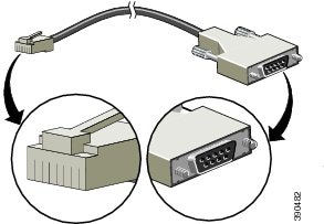
RJ-45 ポートに内蔵 DTE 機能がない場合は、RJ-45-to-RJ-45 ロールオーバ ケーブルまたは DB-9 アダプタなどの DTE アダプタを使用します。 6 フィートの DB9 Female-to-RJ45 コンソール ケーブルを使用できます(別途注文の必要があります。部品番号:72-3383-01)。 図 5. DB9 Female-to-RJ45 ケーブル
-
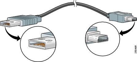
USB コンソール ポート:USB Type A から 5 ピン ミニ タイプ B ケーブルを使用します(別途注文の必要があります。部品番号:37-1090-01)。 図 6. USB タイプ A から USB 5 ピン Mini タイプ B へのケーブル
-
RJ45 コンソール ポート:8 ピン RJ-45 コネクタを使用し、内蔵 DTE 機能があります。
- RJ-45-to-RJ-45 ロールオーバ ケーブルおよび DTE アダプタを使用することで、モデムをコンソール ポートに接続できます。
DB-9 アダプタ(PC に接続)
ターミナル エミュレーション ソフトウェアが稼働している PC にコンソール ポートを接続するには、RJ-45 to RJ-45 ロールオーバー ケーブルと RJ-45 to DB-9 メス型 DTE アダプタ(「Terminal」のラベル)を使用します。
| コンソール ポート | RJ-45 to RJ45 ロールオーバー ケーブル | RJ-45 to DB-9 端末アダプタ | コンソール デバイス |
|
|---|---|---|---|---|
| 信号 |
RJ-45 ピン |
RJ-45 ピン |
DB-9 ピン |
信号 |
| RTS |
15 |
8 |
8 |
CTS |
| DTR |
2 |
7 |
6 |
DSR |
| TxD |
3 |
6 |
2 |
RxD |
| GND |
4 |
5 |
5 |
GND |
| GND |
5 |
4 |
5 |
GND |
| RxD |
6 |
3 |
3 |
TxD |
| DSR |
7 |
2 |
4 |
DTR |
| CTS |
86 |
1 |
7 |
RTS |
DB-25 アダプタ(端末との接続用)
コンソール ポートを端末に接続するには、RJ-45 to RJ-45 ロールオーバー ケーブルと RJ-45 to DB-25 メス型 DTE アダプタ(「Terminal」のラベル)を使用します。
| コンソール ポート | RJ-45 to RJ45 ロールオーバー ケーブル | RJ-45 to DB-25 ターミナル アダプタ | コンソール デバイス |
|
|---|---|---|---|---|
| 信号 |
RJ-45 ピン |
RJ-45 ピン |
DB-25 ピン |
信号 |
| RTS |
17 |
8 |
5 |
CTS |
| DTR |
2 |
7 |
6 |
DSR |
| TxD |
3 |
6 |
3 |
RxD |
| GND |
4 |
5 |
7 |
GND |
| GND |
5 |
4 |
7 |
GND |
| RxD |
6 |
3 |
2 |
TxD |
| DSR |
7 |
2 |
20 |
DTR |
| CTS |
88 |
1 |
4 |
RTS |
モデム アダプタ
コンソール ポートをモデムに接続するには、RJ-45 to RJ-45 ロールオーバー ケーブルと RJ-45 to DB-25 オス型 DCE アダプタ(「Modem」のラベル)を使用します。
| コンソール ポート | RJ-45 to RJ45 ロールオーバー ケーブル | RJ-45 to DB-25 モデム アダプタ | コンソール デバイス |
|
|---|---|---|---|---|
| 信号 |
RJ-45 ピン |
RJ-45 ピン |
DB-25 ピン |
信号 |
| RTS |
19 |
8 |
4 |
CTS |
| DTR |
2 |
7 |
20 |
DSR |
| TxD |
3 |
6 |
3 |
RxD |
| GND |
4 |
5 |
7 |
GND |
| GND |
5 |
4 |
7 |
GND |
| RxD |
6 |
3 |
2 |
TxD |
| DSR |
7 |
2 |
8 |
DTR |
| CTS |
810 |
1 |
5 |
RTS |
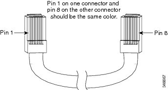
ロールオーバー ケーブルの識別
ロールオーバー ケーブルは、ケーブルの両端を比較すると識別できます。 ケーブルの両端を、タブを裏側にして両手で並べて持った場合に、左のプラグの外側にあるピンに接続されたワイヤと、右のプラグの外側にあるピンに接続されたワイヤとが、同じ色になります シスコ製のケーブルの場合、一方のコネクタではピン 1 が白、もう一方のコネクタではピン 8 が白です。 (ロールオーバー ケーブルは、ピン 1 とピン 8、ピン 2 とピン 7、ピン 3 とピン 6、ピン 4 とピン 5 が反転しています)。
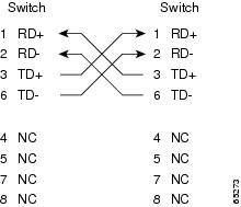
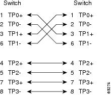
ケーブルのピン割り当て
次の表および図は、スイッチがサポートするケーブルのピン割り当てと設計図を示しています。
| サイド 1 のピン(信号) | サイド 2 のピン(信号) |
|---|---|
| 1(RD+) |
3(TD+) |
| 2(RD-) |
6(TD-) |
| 3(TD+) |
1(RD+) |
| 6(TD-) |
2(RD-) |
| 4(未使用) |
4(未使用) |
| 5(未使用) |
5(未使用) |
| 7(未使用) |
7(未使用) |
| 8(未使用) |
8(未使用) |
| サイド 1 のピン(信号) | サイド 2 のピン(信号) |
|---|---|
| 1(TP0+) |
3(TP1+) |
| 2(TP0-) |
6(TP1-) |
| 3(TP1+) |
1(TP0+) |
| 6(TP1-) |
2(TP1–) |
| 4(TP2+) |
7(TP3+) |
| 5(TP2-) |
8(TP3-) |
| 7(TP3+) |
4(TP2+) |
| 8(TP3-) |
5(TP2-) |
アクセサリ キットには、コンソール(ASCII 端末またはターミナル エミュレーション ソフトウェアを実行する PC)またはモデムをコンソール ポートに接続するケーブルおよびアダプタが含まれています。 アクセサリ キットには、次のものが入っています。
| サイド 1 のピン(信号) | サイド 2 のピン(信号) |
|---|---|
| 1 (Tx) |
12 (Rx) |
| 2 (Tx) |
11 (Rx) |
| 3 (Tx) |
10 (Rx) |
| 4 (Tx) |
9 (Rx) |
| 5(未使用) |
8(未使用) |
| 6(未使用) |
7(未使用) |
| 7(未使用) |
6(未使用) |
| 8(未使用) |
5(未使用) |
| 9 (Rx) |
4 (Tx) |
| 10 (Rx) |
3 (Tx) |
| 11 (Rx) |
2 (Tx) |
| 12 (Rx) |
1 (Tx) |
モードコンディショニング パッチコード
LX/LH(長波長/長距離)GBIC に直径 62.5 ミクロンの MMF ケーブルを使用する場合は、リンクの送信側と受信側の両方で、GBIC と MMF ケーブルとの間にモードコンディショニング パッチコード(シスコ製品番号:CAB-GELX-625 または同等品)を取り付ける必要があります。 FDDI グレード、OM1 および OM2 の各ファイバ ケーブル タイプ上の 1000BASE-LX/LH アプリケーションには、モードコンディショニング パッチ コードが必要です。 モードコンディショニング パッチ コードは、OM3 ファイバ ケーブル(レーザー最適化ファイバ ケーブル)上のアプリケーションには使用できません。 モードコンディショニング パッチコードの詳細については、Cisco.com で入手できる「Use of Mode Conditioning Patch Cables in Gigabit Ethernet and 10 Gigabit Ethernet Laser-Based Transmissions(ギガビット イーサネットおよび 10 ギガビット イーサネット レーザーベースの送信でのモードコンディショニング パッチ ケーブルの使用)」公報を参照してください。
(注) |
ビット エラー レート(BER)の増加につながる可能性があるため、10 ~ 100 m(33 ~ 328 フィート)の非常に短いリンク距離の場合は LX/LH GBIC および MMF に必ずパッチ コードを使用することをお勧めします。 |
IEEE 規格に準拠するためには、パッチコードが必要です。 IEEE は、光ファイバ ケーブル コアの中心の問題によって、特定タイプの光ファイバ ケーブルではリンク距離が適合しないことを確認しています。 問題を解決するには、パッチコードを使用して、正確なオフセットで中心からレーザー光を送出する必要があります。 1000BASE-LX の IEEE 802.3z 規格に対する LX/LH GBIC の準拠は、パッチコードの出力を前提とします。
例:パッチ コードの構成
パッチ コードの取り付け
警告 |
接続されていない光ファイバ ケーブルやコネクタからは目に見えないレーザー光が放射されている可能性があります。 レーザー光を直視したり、光学機器を使用して直接見たりしないでください。 ステートメント 1051 |
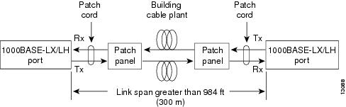
パッチ コードを取り付けるには、次の手順を実行します。
| ステップ 1 | パッチコードの「To Equipment」ラベルが付いている側を、GBIC に差し込みます。 図 1 を参照してください。 |
| ステップ 2 |
パッチコードの「To Cable Plant」ラベルが付いている側を、パッチパネルに接続します。 図 1 を参照してください。 パッチ コードの長さは 3 m(9.8 フィート)で、両端にデュプレックス SC タイプ オス コネクタが付いています。 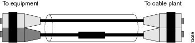
|
DMD
SMF ケーブル用の未調整レーザー光源を MMF ケーブルに直接接続した場合、DMD が発生することがあります。 DMD が発生すると、光ファイバ ケーブルのモード帯域幅が減少し、 信頼性のある伝送を保証できるリンク距離(トランスミッタとレシーバ間の距離)が短くなります。
ギガビット イーサネット仕様(IEEE 802.3z)には、イーサネット通信のパラメータ(Gbps)が規定されています。 802.3z では、レーザーベースの光コンポーネントを使用した MMF ケーブルでのデータ伝送を定義することにより、敷設済みの MMF ケーブルを利用したバックボーンとサーバ間の高速イーサネット接続を提示しています。
レーザーは、ギガビット イーサネットに必要なボー レートと長距離伝送を達成します。 802.3z ギガビット イーサネット標準化委員会は、レーザーと MMF ケーブルの特定の組み合わせでは、一定の条件下で DMD が発生することを明らかにしました。 その結果、他にジッタの要因が発生し、MMF ケーブルによるギガビット イーサネットの到達距離が制限されることがわかっています。
DMD が発生する状況では、単一のレーザー光パルスによって、MMF ケーブル内でいくつかのモードが均等に励振されます。 これらのモード、すなわち光路は、複数の異なる伝搬路をたどります。 伝搬路の長さはそれぞれ異なる場合があるので、ケーブル内を光が進むにつれて、各伝搬路の遅延時間に差異が生じます。 DMD が発生すると、ケーブルを通過する単一パルスの孤立性が損なわれ、極端な場合には、2 つの独立したパルスが生じることがあります。 連鎖パルスは相互に干渉しやすいので、信頼できる方法でデータを回復するのが困難になります。
DMD は、敷設されたすべての光ファイバ ケーブル上で発生するわけではありません。光ファイバとトランシーバの組み合わせが悪い場合に発生します。 ギガビット イーサネットは、ボー レートが非常に高く、MMF ケーブルの距離が長いため、DMD が問題になります。 SMF ケーブルおよび銅ケーブルでは、DMD の問題は起きません。
MMF ケーブルのテストは、LED 光源を使用した場合に限定して行われてきました。 LED は、光ファイバ ケーブル内に「オーバーフィルド ラウンチ条件」と呼ばれる状態を作ります。 オーバーフィルド ラウンチ コンディションは、LED トランスミッタが光ファイバ ケーブル内に、広範囲のモードに拡散した光を入射する状態を意味します。 暗い室内で電球を照らしたときのように、光がさまざまな方向に拡散してケーブル内を満たし、多数のモードが発生します
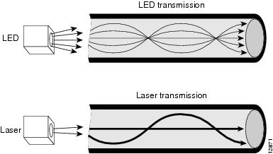
レーザーから入射される光は、LED よりも集束された状態で発光します。 レーザー トランスミッタからの光は、光ファイバ ケーブル内に存在するモード(すなわち光路)のうち、ごく少数のモードだけを通過します 図 1 を参照してください。
DMD の問題を解決するには、光源(トランスミッタ)から入射されたレーザー光が、LED 光源からケーブル内に入射されたときのように、光ファイバ ケーブルの直径に対して均等に分散されるように調整する必要があります。 光のモードをスクランブルすると、光パワーがすべてのモードに均等に分散され、光パワーが少数のモードだけに集中する状況を回避できます。
これに対して未調整の入射状態では、最悪の場合、光ファイバ ケーブルの中心にすべての光が集中し、均等に励振されるモードはごく少数になります。
DMD の発生する度合いは、MMF ケーブルごとに大きく異なります。 敷設されたケーブル設備では、DMD の影響を評価する有効なテスト方法はありません。したがって、リンク スパンが 300 m(984 フィート)を超える場合には、MMF ケーブルを使用するすべてのアップリンク モジュールに、モードコンディショニング パッチコードを使用する必要があります。
リンク スパンが 300 m(984 フィート)未満の場合には、パッチコードを使用しなくてもかまいません。 ビット エラー レート(BER)の増加につながる可能性があるため、10 ~ 100 メートル(33 ~ 328 フィート)の非常に短いリンク距離の場合は LX/LH GBIC および MMF に必ずパッチ コードを使用することをお勧めします。
目次
- トランシーバ、モジュール コネクタ、およびケーブルの仕様
- プラグイン可能なトランシーバ
- 1 GB トランシーバ
- 10 GB トランシーバ
- 40 GB トランシーバ
- WDM トランシーバ
- モジュール コネクタ
- RJ-45 コネクタ
- SC コネクタ
- LC コネクタ
- MTP-12 コネクタ
- 光ファイバ コネクタの清掃
- ガイドライン
- 光ファイバ コネクタを清掃する方法
- ケーブル仕様
- SFP モジュール ケーブル
- コンソール ケーブル
- DB-9 アダプタ(PC に接続)
- DB-25 アダプタ(端末との接続用)
- モデム アダプタ
- ロールオーバー ケーブルの識別
- ケーブルのピン割り当て
- モードコンディショニング パッチコード
- 例:パッチ コードの構成
- パッチ コードの取り付け
- DMD
プラグイン可能なトランシーバ
このセクションでは、スイッチ モジュールおよびスーパーバイザ エンジンに設置できる接続可能なトランシーバについて簡単に説明します。
以下の安全に関する警告が適用されます。
警告
この装置の設置、交換、または保守は、訓練を受けた相応の資格のある人が行ってください。 ステートメント 1030
警告
本製品の最終処分は、各国のすべての法律および規制に従って行ってください。 ステートメント 1040
警告
クラス I(CDRH)およびクラス 1M(IEC)レーザー製品です。 ステートメント 1055
警告
指定された制御、調整、または実行手順以外を使用した場合、危険な放射線に被曝する可能性があります。 ステートメント 1057
1 GB トランシーバ
スイッチは 1 GB SFP トランシーバをサポートしています。 次の表は、 SFP トランシーバがサポートするモジュールと、トランシーバ仕様のリンクの一覧を示しています。
(注)
特定の SFP トランシーバがサポートされるモジュールと互換性があるかどうかを判断するには、Cisco.com で入手できる「Cisco Gigabit Ethernet Transceiver Modules Compatibility Matrix(Cisco ギガビット イーサネット トランシーバ モジュール互換性マトリクス)」を参照してください。
10 GB トランシーバ
スイッチは 10 GB X2 および 10 Gb SFP+ トランシーバをサポートします。 次の表は、トランシーバがサポートするモジュールと、トランシーバ仕様のリンクの一覧を示しています。
表 2 10 GB トランシーバ タイプ 10 GB トランシーバ タイプ
サポートされるモジュール
追加情報
X2 トランシーバ
SFP+ トランシーバ
特定の 10 GB トランシーバがサポートされるモジュールと互換性があるかどうかを判断するには、Cisco.com で入手できる「10-Gigabit Ethernet Transceiver Modules Compatibility Matrix(10 ギガビット イーサネット トランシーバ モジュール互換性マトリクス)」を参照してください。
40 GB トランシーバ
スイッチは 40 ギガビット イーサネット モジュール ポートに接続するホットスワップ可能な I/O デバイスである 40 ギガビット CFP トランシーバ モジュールをサポートします。 CFP トランシーバ モジュールは、光ネットワークとプラットフォームの電気回路を接続します。 次の表は、トランシーバがサポートするモジュールと、トランシーバ仕様のリンクの一覧を示しています。
(注)
特定の 40 GB トランシーバがサポートされるモジュールと互換性があるかどうかを判断するには、Cisco.com で入手できる「Cisco 40-Gigabit Ethernet Transceiver Modules Compatibility Matrix(Cisco 40 ギガビット イーサネット トランシーバ モジュール互換性マトリクス)」を参照してください。
WDM トランシーバ
次の表は、WDM トランシーバをサポートするモジュール、該当の図と仕様表を示しています。
表 4 WDM トランシーバ タイプ WDM トランシーバ タイプ
説明
サポートされるモジュール
追加情報
CWDM SFP
CWDM SFP は、SFP 互換モジュールおよびスーパーバイザ エンジンに装着できるホットスワップ可能なトランシーバ コンポーネントです。 CWDM SFP トランシーバでは、LC 光コネクタを使用して、SMF 光ケーブルに接続します。 SMF 光ケーブルを使用して、CWDM SFP を CWDM Passive Optical System Optical Add/Drop Multiplexer(OADM)モジュールまたはマルチプレクサ/デマルチプレクサ プラグイン モジュールに接続できます。
DWDM SFP
Cisco DWDM SFP は、ギガビット イーサネット SFP ポートまたはスロットに接続するホットスワップ可能な I/O トランシーバ モジュールです。 ITU 100-GHz 波長グリッドをサポートし、Cisco 100-GHz ONS 製品ファミリ向け波長計画に一致します。 40 の異なる SFP モデルを持つ固定波長 SFP です。 標準 SFP インターフェイスのネットワーク、デュアル LC/PC コネクタを使用します。
(注) PC または UPC コネクタを使用するパッチ コードとの接続だけがサポートされます。 APC コネクタを使用するパッチ コードはサポートされません。
Cisco Dense Wavelength-Division Multiplexing Small Form-Factor Pluggable Module
DWDM SFP+
Cisco DWDM SFP+ トランシーバ モジュールは、ポートをネットワークとリンクするシスコ スイッチまたはルータのイーサネット SFP+ ポートに接続するホットスワップ可能な I/O デバイスです。 40 の非調整可能な ITU 100-GHz 波長をサポートします。 また、デジタル オプティカル モニタリング機能と、Cisco スイッチまたはルータでモジュールがシスコによって検証およびテストされている SFP+ モジュールかを判断するのに使用できる Cisco Quality identification(ID)機能をサポートしています。
DWDM X2 Cisco DWDM X2 トランシーバは、ポートをネットワークにリンクするためにスイッチのイーサネット X2 ポートに接続されるホットスワップ可能な I/O モジュールです。 モジュールは Cisco ONS DWDM チャネル計画と互換性がある 32 の非調整 ITU 100-GHz 波長をサポートします。 Cisco DWDM X2 はデジタル オプティカル モニタリング機能をサポートします。
(注)
特定の WDM トランシーバがサポートされるモジュールと互換性があるかどうかを判断するには、Cisco.com で入手できる「Cisco Gigabit Ethernet Transceiver Modules Compatibility Matrix(Cisco ギガビット イーサネット トランシーバ モジュール互換性マトリクス)」を参照してください。
モジュール コネクタ
このセクションでは、スイッチがサポートするモジュール コネクタについて簡単に説明します。
RJ-45 コネクタ
RJ-45 コネクタは、カテゴリ 3、5、5e、または 6 のホイル ツイストペア(FTP)またはシールドなしツイストペア ケーブル(UTP)ケーブルを使用して、モジュールのインターフェイス コネクタと外部ネットワークを接続する場合に使用されます。
注意
カテゴリ 5e、カテゴリ 6、および カテゴリ 6a のケーブルは、誘電性の物質で構成されているため、静電気を大量に帯びる可能性があります。 常にケーブル(特に新規ケーブルの設置)を適切で安全な方法でアースできるようにしてから、モジュールに接続してください。
注意
GR-1089 の建物内雷サージ耐性要件に適合するためには、両端に適切なアースを施した FTP ケーブルを使用する必要があります。
SC コネクタ
SC コネクタは、光ファイバ モジュール ポートまたはトランシーバを外部の SMF または MMF ネットワークに接続するために使用されます。
警告
接続されていない光ファイバ ケーブルやコネクタからは目に見えないレーザー光が放射されている可能性があります。 レーザー光を直視したり、光学機器を使用して直接見たりしないでください。 ステートメント 1051
(注)
接続する前に、光コネクタが汚れていないことを確認してください。 コネクタが汚れていると、光ファイバが損傷したり、データ エラーが発生することがあります。
ネットワーク コネクタは必ずソケットに完全に差し込んでください。 確実な接続は、モジュールを長距離(2 km[1.24 マイル ])ネットワーク、またはモジュールを減衰が大きいと考えられるネットワークに接続する場合、特に重要になります。 LINK LED が点灯しない場合は、ネットワーク ケーブルのプラグを取り外してから、再度モジュール ソケットにしっかり差し込んでください。 プラグの前面プレート(光ファイバの開口部の周辺)に埃や皮脂がたまると大幅な減衰が生じて、光パワー レベルがしきい値を下回り、リンクを確立できなくなることがあります。
注意
コネクタの取り付けまたは取り外しを行うときは、コネクタ ハウジングを損傷したり、ファイバ終端の表面を傷付けないように十分に注意してください。 汚れを防ぐために、使用または接続していないコンポーネントには必ず保護カバーを取り付けてください。 コネクタを取り付ける前に、必ずコネクタを清掃してください。
LC コネクタ
LC 光ファイバ コネクタは、高密度のファイバ接続を提供する小型フォーム ファクタ光ファイバ コネクタです。 LC コネクタは MMF または SMF ケーブルのどちらかとともに使用できます。 LC コネクタには、RJ-45 銅製コネクタと同様のラッチ クリップ機構が使用されています。
警告
接続されていない光ファイバ ケーブルやコネクタからは目に見えないレーザー光が放射されている可能性があります。 レーザー光を直視したり、光学機器を使用して直接見たりしないでください。 ステートメント 1051
(注)
接続する前に、光コネクタが汚れていないことを確認してください。 コネクタが汚れていると、光ファイバが損傷したり、データ エラーが発生することがあります。
光ファイバ コネクタの清掃
2 本の光ファイバを接続するには、光ファイバ コネクタを使用します。 通信システムでこれらのコネクタを使用する場合、適切に接続することがきわめて重要になります。
光ファイバ ケーブルのコネクタは、誤った方法で清掃や接続を行うと損傷することがあります。 光ファイバ コネクタが汚れていたり、損傷していると、復元不能な通信または不正確な通信の原因となります。
光ファイバ コネクタは、電気コネクタまたは電子コネクタとは異なります。 光ファイバ システムでは、光が非常に細いファイバ コアを通じて送信されます。 ファイバ コアの直径は通常 62.5 ミクロン以下であり、埃の粒子の直径は 10 分の 1 ~数ミクロン程度なので、ファイバ コアの終端に埃や汚れがあると、2 つのコアを接続するコネクタ インターフェイスの性能が劣化することになります。 コネクタは正確に差し込む必要があり、コネクタ インターフェイスに異物がまったく付着していない状態でなければなりません。
コネクタ損失または挿入損失は、光ファイバ コネクタの重要なパフォーマンス特性です。 また、リターン ロスも重要な要因です。 リターン ロスとは反射光の量です。反射光が少ないほど接続状態はよくなります。 物理的な接触コネクタの場合、最も優れた製品ではリターン ロスが -40 dB より小さくなっていますが、通常の製品では -20 ~ -30 dB 程度です。
接続の質は、コネクタのタイプと、適切な清掃および接続の 2 つの要因によって影響されます。 光損失の一般的な原因は、光ファイバ コネクタの汚れです。 コネクタは常に清潔にしておいてください。また、使用していないコネクタには必ずダスト カバーを取り付けてください。
任意のケーブルまたはコネクタを取り付ける前に、クリーニング キットに含まれている汚れのないアルコール パッドを使用して、フェルール、ファイバ周囲の白い保護チューブ、およびファイバ終端の表面をきれいに拭いてください。
原因不明の光損失が生じる場合には、一般的な対処としてコネクタを清掃してください。
光ファイバ コネクタを清掃する方法
手順
注意
コネクタの取り付けまたは取り外しを行うときは、コネクタ ハウジングを損傷したり、ファイバ終端の表面を傷付けないように十分に注意してください。 汚れを防ぐために、使用または接続していないコンポーネントには必ず保護カバーを取り付けてください。 コネクタを取り付ける前に、必ずコネクタを清掃してください。
光ファイバ コネクタの清掃には、CLETOP カセット クリーナー(SC コネクタにはタイプ A、MT-RJ コネクタにはタイプ B)を使用してください。清掃方法は、各製品の使用手順を参照してください。
警告
接続されていない光ファイバ ケーブルやコネクタからは目に見えないレーザー光が放射されている可能性があります。 レーザー光を直視したり、光学機器を使用して直接見たりしないでください。 ステートメント 1051
ケーブル仕様
このセクションでは、スイッチでサポートされるケーブルについて説明します。
SFP モジュール ケーブル
ケーブルの仕様については、Cisco.com の次の URL にある『Cisco SFP and SFP+ Transceiver Module Installation Notes(Cisco SFP および SFP+ Transceiver モジュール設置ノート)』を参照してください。http://www.cisco.com/c/en/us/td/docs/interfaces_modules/transceiver_modules/installation/note/78_15160.html
各ポートはケーブルの反対側の波長仕様と一致させる必要があります。また、ケーブルは規定のケーブル長を超えないものとします。 銅線 1000BASE-T SFP モジュール トランシーバは、カテゴリ 5 の標準 4 ツイストペア ケーブルを使用します。最大ケーブル長は 328 フィート(100 m)です。
コンソール ケーブル
スーパーバイザ エンジンの前面パネルにあるコンソール ポートを使用してコンソール ポートに端末またはモデムを接続することができます。
DB-9 アダプタ(PC に接続)
ターミナル エミュレーション ソフトウェアが稼働している PC にコンソール ポートを接続するには、RJ-45 to RJ-45 ロールオーバー ケーブルと RJ-45 to DB-9 メス型 DTE アダプタ(「Terminal」のラベル)を使用します。
この表は、非同期シリアル コンソール ポート、RJ-45 to RJ-45 ロールオーバー ケーブル、RJ-45 to DB-9 メス型 DTE アダプタのピン割り当てを示しています。
表 5 ポート モード 1 の信号およびピン割り当て(DB-9 アダプタ)コンソール ポート RJ-45 to RJ45 ロールオーバー ケーブル RJ-45 to DB-9 端末アダプタ コンソール
デバイス
信号
RJ-45 ピン
RJ-45 ピン
DB-9 ピン
信号
RTS
15
8
8
CTS
DTR
2
7
6
DSR
TxD
3
6
2
RxD
GND
4
5
5
GND
GND
5
4
5
GND
RxD
6
3
3
TxD
DSR
7
2
4
DTR
CTS
86
1
7
RTS
5 ピン 1 は内部でピン 8 に接続されています。6 ピン 1 は内部でピン 8 に接続されています。DB-25 アダプタ(端末との接続用)
コンソール ポートを端末に接続するには、RJ-45 to RJ-45 ロールオーバー ケーブルと RJ-45 to DB-25 メス型 DTE アダプタ(「Terminal」のラベル)を使用します。
この表は、非同期シリアル コンソール ポート、RJ-45 to RJ-45 ロールオーバー ケーブル、RJ-45 to DB-25 メス型 DTE アダプタのピン割り当てを示します。
表 6 ポート モード 1 の信号およびピン割り当て(DB-25 アダプタ)コンソール ポート RJ-45 to RJ45 ロールオーバー ケーブル RJ-45 to DB-25 ターミナル アダプタ コンソール
デバイス
信号
RJ-45 ピン
RJ-45 ピン
DB-25 ピン
信号
RTS
17
8
5
CTS
DTR
2
7
6
DSR
TxD
3
6
3
RxD
GND
4
5
7
GND
GND
5
4
7
GND
RxD
6
3
2
TxD
DSR
7
2
20
DTR
CTS
88
1
4
RTS
7 ピン 1 は内部でピン 8 に接続されています。8 ピン 1 は内部でピン 8 に接続されています。モデム アダプタ
コンソール ポートをモデムに接続するには、RJ-45 to RJ-45 ロールオーバー ケーブルと RJ-45 to DB-25 オス型 DCE アダプタ(「Modem」のラベル)を使用します。
表は、非同期シリアル AUX ポート、RJ-45 to RJ-45 ロールオーバー ケーブル、RJ-45 to DB-25 オス型 DCE アダプタのピン割り当てを示しています。
表 7 ポート モード 1 の信号およびピン割り当て(モデム アダプタ)コンソール ポート RJ-45 to RJ45 ロールオーバー ケーブル RJ-45 to DB-25 モデム アダプタ コンソール
デバイス
信号
RJ-45 ピン
RJ-45 ピン
DB-25 ピン
信号
RTS
19
8
4
CTS
DTR
2
7
20
DSR
TxD
3
6
3
RxD
GND
4
5
7
GND
GND
5
4
7
GND
RxD
6
3
2
TxD
DSR
7
2
8
DTR
CTS
810
1
5
RTS
9 ピン 1 は内部でピン 8 に接続されています。10 ピン 1 は内部でピン 8 に接続されています。ケーブルのピン割り当て
表 9 1000BASE-T クロス ケーブルのピン割り当て(MDI-X)サイド 1 のピン(信号) サイド 2 のピン(信号) 1(TP0+)
3(TP1+)
2(TP0-)
6(TP1-)
3(TP1+)
1(TP0+)
6(TP1-)
2(TP1–)
4(TP2+)
7(TP3+)
5(TP2-)
8(TP3-)
7(TP3+)
4(TP2+)
8(TP3-)
5(TP2-)
アクセサリ キットには、コンソール(ASCII 端末またはターミナル エミュレーション ソフトウェアを実行する PC)またはモデムをコンソール ポートに接続するケーブルおよびアダプタが含まれています。 アクセサリ キットには、次のものが入っています。
モードコンディショニング パッチコード
LX/LH(長波長/長距離)GBIC に直径 62.5 ミクロンの MMF ケーブルを使用する場合は、リンクの送信側と受信側の両方で、GBIC と MMF ケーブルとの間にモードコンディショニング パッチコード(シスコ製品番号:CAB-GELX-625 または同等品)を取り付ける必要があります。 FDDI グレード、OM1 および OM2 の各ファイバ ケーブル タイプ上の 1000BASE-LX/LH アプリケーションには、モードコンディショニング パッチ コードが必要です。 モードコンディショニング パッチ コードは、OM3 ファイバ ケーブル(レーザー最適化ファイバ ケーブル)上のアプリケーションには使用できません。 モードコンディショニング パッチコードの詳細については、Cisco.com で入手できる「Use of Mode Conditioning Patch Cables in Gigabit Ethernet and 10 Gigabit Ethernet Laser-Based Transmissions(ギガビット イーサネットおよび 10 ギガビット イーサネット レーザーベースの送信でのモードコンディショニング パッチ ケーブルの使用)」公報を参照してください。
(注)
ビット エラー レート(BER)の増加につながる可能性があるため、10 ~ 100 m(33 ~ 328 フィート)の非常に短いリンク距離の場合は LX/LH GBIC および MMF に必ずパッチ コードを使用することをお勧めします。
IEEE 規格に準拠するためには、パッチコードが必要です。 IEEE は、光ファイバ ケーブル コアの中心の問題によって、特定タイプの光ファイバ ケーブルではリンク距離が適合しないことを確認しています。 問題を解決するには、パッチコードを使用して、正確なオフセットで中心からレーザー光を送出する必要があります。 1000BASE-LX の IEEE 802.3z 規格に対する LX/LH GBIC の準拠は、パッチコードの出力を前提とします。
パッチ コードの取り付け
手順
警告
接続されていない光ファイバ ケーブルやコネクタからは目に見えないレーザー光が放射されている可能性があります。 レーザー光を直視したり、光学機器を使用して直接見たりしないでください。 ステートメント 1051
パッチ コードを取り付けるには、次の手順を実行します。
ステップ 1 パッチコードの「To Equipment」ラベルが付いている側を、GBIC に差し込みます。 図 1 を参照してください。 ステップ 2 パッチコードの「To Cable Plant」ラベルが付いている側を、パッチパネルに接続します。 図 1 を参照してください。 パッチ コードの長さは 3 m(9.8 フィート)で、両端にデュプレックス SC タイプ オス コネクタが付いています。
DMD
SMF ケーブル用の未調整レーザー光源を MMF ケーブルに直接接続した場合、DMD が発生することがあります。 DMD が発生すると、光ファイバ ケーブルのモード帯域幅が減少し、 信頼性のある伝送を保証できるリンク距離(トランスミッタとレシーバ間の距離)が短くなります。
ギガビット イーサネット仕様(IEEE 802.3z)には、イーサネット通信のパラメータ(Gbps)が規定されています。 802.3z では、レーザーベースの光コンポーネントを使用した MMF ケーブルでのデータ伝送を定義することにより、敷設済みの MMF ケーブルを利用したバックボーンとサーバ間の高速イーサネット接続を提示しています。
レーザーは、ギガビット イーサネットに必要なボー レートと長距離伝送を達成します。 802.3z ギガビット イーサネット標準化委員会は、レーザーと MMF ケーブルの特定の組み合わせでは、一定の条件下で DMD が発生することを明らかにしました。 その結果、他にジッタの要因が発生し、MMF ケーブルによるギガビット イーサネットの到達距離が制限されることがわかっています。
DMD が発生する状況では、単一のレーザー光パルスによって、MMF ケーブル内でいくつかのモードが均等に励振されます。 これらのモード、すなわち光路は、複数の異なる伝搬路をたどります。 伝搬路の長さはそれぞれ異なる場合があるので、ケーブル内を光が進むにつれて、各伝搬路の遅延時間に差異が生じます。 DMD が発生すると、ケーブルを通過する単一パルスの孤立性が損なわれ、極端な場合には、2 つの独立したパルスが生じることがあります。 連鎖パルスは相互に干渉しやすいので、信頼できる方法でデータを回復するのが困難になります。
DMD は、敷設されたすべての光ファイバ ケーブル上で発生するわけではありません。光ファイバとトランシーバの組み合わせが悪い場合に発生します。 ギガビット イーサネットは、ボー レートが非常に高く、MMF ケーブルの距離が長いため、DMD が問題になります。 SMF ケーブルおよび銅ケーブルでは、DMD の問題は起きません。
MMF ケーブルのテストは、LED 光源を使用した場合に限定して行われてきました。 LED は、光ファイバ ケーブル内に「オーバーフィルド ラウンチ条件」と呼ばれる状態を作ります。 オーバーフィルド ラウンチ コンディションは、LED トランスミッタが光ファイバ ケーブル内に、広範囲のモードに拡散した光を入射する状態を意味します。 暗い室内で電球を照らしたときのように、光がさまざまな方向に拡散してケーブル内を満たし、多数のモードが発生します
レーザーから入射される光は、LED よりも集束された状態で発光します。 レーザー トランスミッタからの光は、光ファイバ ケーブル内に存在するモード(すなわち光路)のうち、ごく少数のモードだけを通過します 図 1 を参照してください。
DMD の問題を解決するには、光源(トランスミッタ)から入射されたレーザー光が、LED 光源からケーブル内に入射されたときのように、光ファイバ ケーブルの直径に対して均等に分散されるように調整する必要があります。 光のモードをスクランブルすると、光パワーがすべてのモードに均等に分散され、光パワーが少数のモードだけに集中する状況を回避できます。
これに対して未調整の入射状態では、最悪の場合、光ファイバ ケーブルの中心にすべての光が集中し、均等に励振されるモードはごく少数になります。
DMD の発生する度合いは、MMF ケーブルごとに大きく異なります。 敷設されたケーブル設備では、DMD の影響を評価する有効なテスト方法はありません。したがって、リンク スパンが 300 m(984 フィート)を超える場合には、MMF ケーブルを使用するすべてのアップリンク モジュールに、モードコンディショニング パッチコードを使用する必要があります。
リンク スパンが 300 m(984 フィート)未満の場合には、パッチコードを使用しなくてもかまいません。 ビット エラー レート(BER)の増加につながる可能性があるため、10 ~ 100 メートル(33 ~ 328 フィート)の非常に短いリンク距離の場合は LX/LH GBIC および MMF に必ずパッチ コードを使用することをお勧めします。
 フィードバック