- マニュアルの概要
- クイック スタート手順
- FWSM について
- Firewall Services Module を使用する ためのスイッチの設定
- Firewall Services Module の接続およ び設定の管理
- セキュリティ コンテキストの設定
- ファイアウォール モードの設定
- インターフェイス パラメータの設定
- 基本設定
- IP ルーティングおよび DHCP サービス の設定
- IPv6 の設定
- アクセス リストでのトラフィックの 識別
- ネットワーク アクセスの許可または 拒否
- NAT の設定
- フェールオーバーの設定
- AAA サーバとローカル データベース の設定
- ネットワーク アクセスへの AAA の 適用
- フィルタリング サービスの適用
- ARP 検査およびブリッジング パラメー タの設定
- モジュラ ポリシー フレームワークの 使用
- ネットワーク攻撃の回避
- アプリケーション レイヤ プロトコル 検査の適用
- 管理アクセスの設定
- ソフトウェア、ライセンス、および設 定の管理
- FWSM のモニタリング
- FWSM のトラブルシューティング
- 仕様
- 設定例
- CLI の使用
- アドレス、プロトコル、およびポート
- 用語集
- 索引
Catalyst 6500 シリーズ スイッチ/Cisco 7600 シリーズ ルータ Firewall Services Module コンフィギュレーション ガイド Release 3.1(1)
偏向のない言語
この製品のマニュアルセットは、偏向のない言語を使用するように配慮されています。このマニュアルセットでの偏向のない言語とは、年齢、障害、性別、人種的アイデンティティ、民族的アイデンティティ、性的指向、社会経済的地位、およびインターセクショナリティに基づく差別を意味しない言語として定義されています。製品ソフトウェアのユーザーインターフェイスにハードコードされている言語、RFP のドキュメントに基づいて使用されている言語、または参照されているサードパーティ製品で使用されている言語によりドキュメントに例外が存在する場合があります。シスコのインクルーシブランゲージに対する取り組みの詳細は、こちらをご覧ください。
翻訳について
このドキュメントは、米国シスコ発行ドキュメントの参考和訳です。リンク情報につきましては、日本語版掲載時点で、英語版にアップデートがあり、リンク先のページが移動/変更されている場合がありますことをご了承ください。あくまでも参考和訳となりますので、正式な内容については米国サイトのドキュメントを参照ください。
- Updated:
- 2017年5月28日
章のタイトル: Firewall Services Module を使用する ためのスイッチの設定
Firewall Services Module を使用するためのスイッチの設定
この章では、FWSM と組み合わせて使用できるように、Catalyst 6500 シリーズ スイッチまたは Cisco 7600 シリーズ ルータを設定する方法について説明します。この章で説明する作業を行う前に、スイッチに付属のマニュアルに従って、インターフェイスへの VLAN 割り当てをはじめ、スイッチの基本的なプロパティを設定してください。
スイッチの概要
FWSM は、Cisco 6500 シリーズ スイッチまたは Cisco 7600 シリーズ ルータに搭載できます。どちらのシリーズもコンフィギュレーションは同じです。このマニュアルでは両方のシリーズをまとめて「スイッチ」と呼びます。スイッチには、スイッチ(スーパーバイザ エンジン)とともにルータ(Multilayer Switch Feature Card[MSFC; マルチレイヤ スイッチ フィーチャ カード])が搭載されています。
スイッチは 2 種類のソフトウェア モードをサポートします。
•![]() スイッチのスーパーバイザ エンジンおよび内蔵 MSFC ルータの両方で、Cisco IOS ソフトウェアを使用
スイッチのスーパーバイザ エンジンおよび内蔵 MSFC ルータの両方で、Cisco IOS ソフトウェアを使用
•![]() スーパーバイザ エンジンで Catalyst Operating System(OS;オペレーティング システム)ソフトウェア、MSFC 上で Cisco IOS ソフトウェアを使用
スーパーバイザ エンジンで Catalyst Operating System(OS;オペレーティング システム)ソフトウェア、MSFC 上で Cisco IOS ソフトウェアを使用
MSFC の詳細については、「MSFC の使用方法」を参照してください。

(注) スイッチでは、各 FWSM で SPAN リフレクタ機能がイネーブルです。この機能によって、FWSM から送られてきたマルチキャスト トラフィック(および中央の書き換えエンジンが必要な他のトラフィック)をスイッチングできます。SPAN リフレクタ機能は SPAN セッションを 1 つ使用します。この機能をディセーブルにするには、次のコマンドを入力します。
モジュールの搭載確認
スイッチが FWSM を認識してオンラインにしているかどうかを確認するには、OS に応じてモジュール情報を表示します。
(注) show module コマンドの出力に FWSM の 6 ポートが示されています。これは、EtherChannel としてひとまとめにされた内部ポートです。詳細については、「FWSM の内部インターフェイスのカスタマイズ」を参照してください。
Firewall Services Module への VLAN 割り当て
ここでは、FWSM に VLAN を割り当てる方法について説明します。FWSM に外部物理インターフェイスは組み込まれていません。代わりに VLAN インターフェイスを使用します。FWSM への VLAN 割り当ては、スイッチ ポートへの VLAN 割り当てと同様です。FWSM には Switch Fabric Module(SFM; スイッチ ファブリック モジュール)(搭載されている場合)または共有バスへの内部インターフェイスがあります。
(注) VLAN をスイッチに追加してスイッチ ポートに割り当てる方法については、スイッチのマニュアルを参照してください。
•![]() 「Cisco IOS ソフトウェアで FWSM に VLAN を割り当てる場合」
「Cisco IOS ソフトウェアで FWSM に VLAN を割り当てる場合」
•![]() 「Catalyst OS ソフトウェアで FWSM に VLAN を割り当てる場合」
「Catalyst OS ソフトウェアで FWSM に VLAN を割り当てる場合」
VLAN の注意事項
FWSM で VLAN を使用する際の注意事項は、次のとおりです。
•![]() FWSM でプライベート VLAN を使用できます。FWSM にプライマリ VLAN を割り当てると、FWSM は自動的にセカンダリ VLAN トラフィックを処理します。
FWSM でプライベート VLAN を使用できます。FWSM にプライマリ VLAN を割り当てると、FWSM は自動的にセカンダリ VLAN トラフィックを処理します。
•![]() 同一スイッチ シャーシ内で FWSM フェールオーバーを使用する場合は、フェールオーバーおよびステートフル通信のために確保してある VLAN(複数可)を割り当てないでください。ただし、シャーシ間でフェールオーバーを使用する場合は、シャーシ間を結ぶトランク ポートに VLAN を組み込む必要があります。
同一スイッチ シャーシ内で FWSM フェールオーバーを使用する場合は、フェールオーバーおよびステートフル通信のために確保してある VLAN(複数可)を割り当てないでください。ただし、シャーシ間でフェールオーバーを使用する場合は、シャーシ間を結ぶトランク ポートに VLAN を組み込む必要があります。
•![]() FWSM に VLAN を割り当てる前に、スイッチに VLAN を追加しなかった場合、VLAN はスーパーバイザ エンジンのデータベースに保管され、スイッチに追加された時点で FWSM に送信されます。
FWSM に VLAN を割り当てる前に、スイッチに VLAN を追加しなかった場合、VLAN はスーパーバイザ エンジンのデータベースに保管され、スイッチに追加された時点で FWSM に送信されます。
•![]() MSFC に割り当てる前に、FWSM に VLAN を割り当てます。
MSFC に割り当てる前に、FWSM に VLAN を割り当てます。
この条件を満たしていない VLAN は、FWSM 上で割り当てる VLAN の範囲から破棄されます。詳細については、「MSFC への SVI の追加」を参照してください。
Cisco IOS ソフトウェアで FWSM に VLAN を割り当てる場合
Cisco IOS ソフトウェアでは、1 つまたは複数のファイアウォール VLAN グループを作成し、FWSM にグループを割り当てます。たとえば、すべての VLAN を 1 つのグループに割り当てる、内部グループと外部グループを作成する、またはカスタマーごとにグループを 1 つずつ作成するといったことが可能です。
1 つの VLAN を複数のファイアウォール グループに割り当てることはできませんが、複数のファイアウォール グループを 1 つの FWSM に割り当てたり、1 つのファイアウォール グループを複数の FWSM に割り当てることはできます。複数の FWSM に割り当てる VLAN は、各 FWSM に固有な VLAN とは別個のグループに配置できます。
VLAN を FWSM に 割り当てる手順は、次のとおりです。
ステップ 1![]() 次のコマンドを入力して、ファイアウォール グループに VLAN を割り当てます。
次のコマンドを入力して、ファイアウォール グループに VLAN を割り当てます。
vlan_range には、次のどちらかの形式で、1 つまたは複数の VLAN(1 ~ 1000 および 1025 ~ 4094)を指定できます。
番号または範囲はカンマで区切ります。番号の入力例を示します。
(注) ルーテッド ポートと WAN ポートは内部 VLAN を使用するので、1020 ~ 1100 の範囲に含まれる番号は、すでに使用されている可能性があります。
ステップ 2![]() 次のコマンドを入力して、FWSM にファイアウォール グループを割り当てます。
次のコマンドを入力して、FWSM にファイアウォール グループを割り当てます。
firewall_group は、1 つまたは複数のグループ番号です。
番号または範囲はカンマで区切ります。番号の入力例を示します。
次に、3 つのファイアウォール VLAN グループ(各 FWSM 用のグループ、および両方の FWSM に割り当てられた VLAN を含むグループ)を作成する例を示します。
次に、show firewall vlan-group コマンドの出力例を示します。
次に、すべての VLAN グループを示す show firewall module コマンドの出力例を示します。
Catalyst OS ソフトウェアで FWSM に VLAN を割り当てる場合
Catalyst OS ソフトウェアで、FWSM に VLAN リストを割り当てます。必要であれば、複数の FWSM に同じ VLAN を割り当ててもかまいません。
次のコマンドを入力して、FWSM に VLAN を割り当てます。
vlan_list には、次のいずれかの形式で、1 つまたは複数の VLAN(2 ~ 1000 および 1025 ~ 4094)を指定できます。
(注) ルーテッド ポートと WAN ポートは内部 VLAN を使用するので、1020 ~ 1100 の範囲に含まれる番号は、すでに使用されている可能性があります。
次に、show vlan firewall-vlan コマンドの出力例を示します。
MSFC への SVI の追加
MSFC 上で定義された VLAN を Switch Virtual Interface(SVI; スイッチ仮想インターフェイス)といいます。FWSM に SVI 用の VLAN を割り当てると(Firewall Services Module への VLAN 割り当てを参照)、MSFC は FWSM と他のレイヤ 3 VLAN 間でルーティングを行います。
•![]() 「SVI の設定(スーパーバイザ エンジンで Cisco IOS ソフトウェアを実行している場合)」
「SVI の設定(スーパーバイザ エンジンで Cisco IOS ソフトウェアを実行している場合)」
•![]() 「SVI の設定(スーパーバイザ エンジンで Catalyst OS ソフトウェアを実行している場合)」
「SVI の設定(スーパーバイザ エンジンで Catalyst OS ソフトウェアを実行している場合)」
SVI の概要
セキュリティ上の理由から、デフォルトでは MSFC と FWSM 間に存在できる SVI は 1 つだけです。たとえば、誤って複数の SVI を指定してシステムを設定した場合、MSFC に内部 VLAN と外部 VLAN の両方を割り当てることによって、トラフィックが偶発的に FWSM をバイパスしてしまう可能性があります(図2-1を参照)。
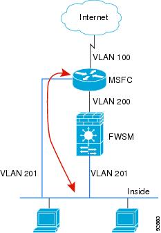
ただし、ネットワークの状況によっては、FWSM をバイパスしなければならないこともあります。図2-2に、IP ホストと同じイーサネット セグメント上に IPX ホストが配置されている例を示します。ルーテッド ファイアウォール モードの FWSM が処理できるのは IP トラフィックだけであり、IPX などの他のトラフィックは廃棄されるので(透過ファイアウォール モードでは任意で IP 以外のトラフィックの通過が可能)、IPX トラフィックは FWSM をバイパスさせる必要があります。この場合、必ず、VLAN 201 を通過できるのが IPX トラフィックに限定されるアクセス リストを使用して MSFC を設定してください。

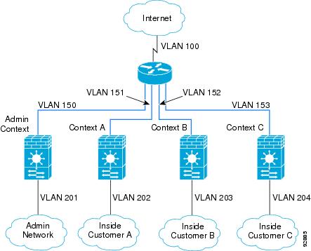
透過ファイアウォールがマルチコンテキスト モードの場合、コンテキストごとに対応する外部インターフェイス上に固有の VLAN が必要なので、複数の SVI を使用する必要があります(図2-3を参照)。ルーテッド モードの場合でも複数の SVI を使用できるので、外部インターフェイス用に 1 つの VLAN を共有する必要はありません。
SVI の設定(スーパーバイザ エンジンで Cisco IOS ソフトウェアを実行している場合)
スーパーバイザ エンジンで Cisco IOS ソフトウェアを実行している場合、次の手順で MSFC に SVI を追加します。
ステップ 1![]() (任意)次のコマンドを入力して、FWSM に複数の SVI を追加できるようにします。
(任意)次のコマンドを入力して、FWSM に複数の SVI を追加できるようにします。
ステップ 2![]() 次のコマンドを入力して、MSFC に VLAN インターフェイスを追加します。
次のコマンドを入力して、MSFC に VLAN インターフェイスを追加します。
ステップ 3![]() 次のコマンドを入力して、MSFC 上でこのインターフェイスに対応する IP アドレスを設定します。
次のコマンドを入力して、MSFC 上でこのインターフェイスに対応する IP アドレスを設定します。
ステップ 4![]() 次のコマンドを入力して、インターフェイスをイネーブルにします。
次のコマンドを入力して、インターフェイスをイネーブルにします。
次に、show interface コマンドの出力例を示します。
SVI の設定(スーパーバイザ エンジンで Catalyst OS ソフトウェアを実行している場合)
スーパーバイザ エンジンで Catalyst OS ソフトウェアを実行している場合、次の手順で MSFC に SVI を追加します。
ステップ 1![]() (任意)次のコマンドを入力して、FWSM に複数の SVI を追加できるようにします。
(任意)次のコマンドを入力して、FWSM に複数の SVI を追加できるようにします。
この設定をディセーブルにするには、次のコマンドを入力します。
ステップ 2![]() 次のコマンドのいずれかを入力して、MSFC インターフェイスにアクセスします。
次のコマンドのいずれかを入力して、MSFC インターフェイスにアクセスします。
Telnet または Secure Shell(SSH; セキュア シェル)を使用してスイッチにアクセスしている場合は、 session コマンドを使用する必要があります。
ステップ 3![]() 次のコマンドを入力して、MSFC 上でイネーブル モードを開始し、さらにコンフィギュレーション モードを開始します。
次のコマンドを入力して、MSFC 上でイネーブル モードを開始し、さらにコンフィギュレーション モードを開始します。
# configure terminal
ステップ 4![]() 次のコマンドを入力して、MSFC に VLAN インターフェイスを追加します。
次のコマンドを入力して、MSFC に VLAN インターフェイスを追加します。
ステップ 5![]() 次のコマンドを入力して、MSFC 上でこのインターフェイスに対応する IP アドレスを設定します。
次のコマンドを入力して、MSFC 上でこのインターフェイスに対応する IP アドレスを設定します。
ステップ 6![]() 次のコマンドを入力して、インターフェイスをイネーブルにします。
次のコマンドを入力して、インターフェイスをイネーブルにします。
ステップ 7![]() 次のコマンドを入力して、イネーブル EXEC モードに戻ります。
次のコマンドを入力して、イネーブル EXEC モードに戻ります。
ステップ 8![]() Ctrl-C を 3 回入力して、スイッチの CLI に戻ります。
Ctrl-C を 3 回入力して、スイッチの CLI に戻ります。
次に、MSFC プロンプトに入力する show interface コマンドの出力例を示します。
FWSM の内部インターフェイスのカスタマイズ
FWSM とスイッチ間の接続は 6 GB の 802.1Q トランキング EtherChannel です。この EtherChannel は、FWSM を搭載した時点で自動的に作成されます。FWSM 側では、2 つの NP のそれぞれが 3 つのギガビット イーサネット インターフェイスに接続し、これらのインターフェイスが EtherChannel を形成します。スイッチはセッション情報に基づき、分散アルゴリズムに従って EtherChannel 内のインターフェイスにトラフィックを分散させます。負荷分散はパケット単位ではなく、フロー単位で行われます。アルゴリズムがインターフェイス間、したがって 2 つの NP 間でトラフィックを均等に割り当てない場合もあります。恒常的な不均衡は、FWSM の処理能力がフル活用されないだけではなく、複数のコンテキストにリソース管理を適用したときに予想外の動作を引き起こす可能性があります(詳細については、 クラスの設定を参照)。
フェールオーバーを使用するためのスイッチの設定
フェールオーバー対応としてスイッチを設定する場合は、次の項を参照してください。
•![]() 「セカンダリ Firewall Services Module への VLAN 割り当て」
「セカンダリ Firewall Services Module への VLAN 割り当て」
•![]() 「プライマリ スイッチとセカンダリ スイッチ間のトランクの追加」
「プライマリ スイッチとセカンダリ スイッチ間のトランクの追加」
セカンダリ Firewall Services Module への VLAN 割り当て
両方の装置が同じように内部ネットワークと外部ネットワークにアクセスできなければならないので、スイッチ上の両方の FWSM に同じ VLAN を割り当てる必要があります。 「Firewall Services Module への VLAN 割り当て」を参照してください。
プライマリ スイッチとセカンダリ スイッチ間のトランクの追加
スイッチ間フェールオーバーを使用している場合( シャーシ内およびシャーシ間のモジュール配置を参照)、2 つのスイッチ間に 802.1Q VLAN トランクを設定してフェールオーバーとステート リンクを処理する必要があります。CoS 値が 5(ハイ プライオリティ)のフェールオーバー VLAN パケットがこれらのポートでハイ プライオリティで処理されるように、トランクで Quality of Service(QoS; サービス品質)をイネーブルにしておく必要があります。
透過ファイアウォール モードとの両立
透過モードでフェールオーバーを使用したときにループが発生しないように、Bridge Protocol Data Unit(BPDU; ブリッジ プロトコル データ ユニット)の転送をサポートするスイッチ ソフトウェアを使用してください。透過ファイアウォール モードでのスイッチのサポートの詳細については、「スイッチ ハードウェアおよびソフトウェアの互換性」を参照してください。
Firewall Services Module ブート パーティションの管理
ここでは、スイッチから FWSM をリセットする方法とフラッシュ メモリ カード上のブート パーティションを管理する方法について説明します。ここでは、次の内容について説明します。
•![]() 「FWSM のリセットまたは特定のパーティションからの起動」
「FWSM のリセットまたは特定のパーティションからの起動」
フラッシュ メモリの概要
FWSM には、OS、コンフィギュレーション、およびその他のデータを保管する 128 MB のフラッシュ メモリ カードがあります。フラッシュ メモリにはパーティションが 6 つあります。Cisco IOS および Catalyst OS ソフトウェアのコマンドでは、 cf: n で指定します。
•![]() メンテナンス パーティション( cf:1 ) ― メンテナンス ソフトウェアが格納されています。メンテナンス ソフトウェアを使用して、アプリケーション パーティションの起動ができない場合に、アプリケーション イメージをアップグレードまたはインストールしたり、アプリケーション イメージのパスワードをリセットしたり、クラッシュ ダンプ情報を表示したりします。
メンテナンス パーティション( cf:1 ) ― メンテナンス ソフトウェアが格納されています。メンテナンス ソフトウェアを使用して、アプリケーション パーティションの起動ができない場合に、アプリケーション イメージをアップグレードまたはインストールしたり、アプリケーション イメージのパスワードをリセットしたり、クラッシュ ダンプ情報を表示したりします。
•![]() ネットワーク コンフィギュレーション パーティション( cf:2 ) ― メンテナンス ソフトウェアのネットワーク コンフィギュレーションが格納されています。FWSM が TFTP サーバにアクセスしてアプリケーション ソフトウェア イメージをダウンロードできるように、メンテナンス ソフトウェアには IP の設定値が必要です。
ネットワーク コンフィギュレーション パーティション( cf:2 ) ― メンテナンス ソフトウェアのネットワーク コンフィギュレーションが格納されています。FWSM が TFTP サーバにアクセスしてアプリケーション ソフトウェア イメージをダウンロードできるように、メンテナンス ソフトウェアには IP の設定値が必要です。
•![]() クラッシュ ダンプ パーティション( cf:3 ) ― クラッシュ ダンプ情報が保管されます。
クラッシュ ダンプ パーティション( cf:3 ) ― クラッシュ ダンプ情報が保管されます。
•![]() アプリケーション パーティション( cf:4 および cf:5 ) ― アプリケーション ソフトウェア イメージ、システム コンフィギュレーション、および ASDM を保管します。デフォルトで、イメージは cf:4 にインストールされます。 cf:5 はテスト パーティションとして使用できます。たとえば、ソフトウェアをアップグレードする場合、新しいソフトウェアを cf:5 にインストールし、問題が発生した場合のバックアップとして旧ソフトウェアを維持することもできます。各パーティションには独自のスタートアップ コンフィギュレーションが設定されています。
アプリケーション パーティション( cf:4 および cf:5 ) ― アプリケーション ソフトウェア イメージ、システム コンフィギュレーション、および ASDM を保管します。デフォルトで、イメージは cf:4 にインストールされます。 cf:5 はテスト パーティションとして使用できます。たとえば、ソフトウェアをアップグレードする場合、新しいソフトウェアを cf:5 にインストールし、問題が発生した場合のバックアップとして旧ソフトウェアを維持することもできます。各パーティションには独自のスタートアップ コンフィギュレーションが設定されています。
•![]() セキュリティ コンテキスト パーティション( cf:6 ) ― このパーティション専用として 64 MB が確保されます。ここにはセキュリティ コンテキスト コンフィギュレーション(必要に応じて)とナビゲーション可能なファイル システムの RSA キーを保管します。他のパーティションには、ファイルのリスト表示などの一般的な作業を実行できるファイル システムはありません。 copy コマンドの使用時には、このパーティションを ディスク といいます。
セキュリティ コンテキスト パーティション( cf:6 ) ― このパーティション専用として 64 MB が確保されます。ここにはセキュリティ コンテキスト コンフィギュレーション(必要に応じて)とナビゲーション可能なファイル システムの RSA キーを保管します。他のパーティションには、ファイルのリスト表示などの一般的な作業を実行できるファイル システムはありません。 copy コマンドの使用時には、このパーティションを ディスク といいます。
デフォルト ブート パーティションの設定
FWSM はデフォルトで、 cf:4 アプリケーション パーティションから起動します。 cf:5 アプリケーション パーティションからの起動または cf:1 メンテナンス パーティションでの起動を選択することもできます。デフォルト ブート パーティションを変更するには、OS に応じたコマンドを入力します。
n は 1(メンテナンス)、4(アプリケーション)、または 5(アプリケーション)です。
n は 1(メンテナンス)、4(アプリケーション)、または 5(アプリケーション)です。
現在のブート パーティションを表示するには、OS に応じたコマンドを入力します。
FWSM のリセットまたは特定のパーティションからの起動
ここでは、FWSM をリセットする方法または特定のパーティションから起動する方法について説明します。CLI または外部 Telnet セッションから FWSM にアクセスできない場合は、FWSM のリセットが必要です。メンテナンス パーティションにアクセスしなければならない場合、またはバックアップのアプリケーション パーティションに保管されている別のソフトウェア イメージから起動しなければならない場合は、デフォルト以外のブート パーティションからの起動が必要になります。メンテナンス パーティションは、トラブルシューティング時に役立ちます。
Cisco IOS ソフトウェアの場合、FWSM のリセット時に、フルメモリ テストの実行を選択することもできます。FWSM の初回起動時には、部分的なメモリ テストが実行されるだけです。フルメモリ テストには、6 分ほどかかります。
FWSM をリセットする場合は、使用する OS に応じた項を参照してください。
•![]() 「Cisco IOS ソフトウェアで FWSM をリセットする場合」
「Cisco IOS ソフトウェアで FWSM をリセットする場合」
•![]() 「Catalyst OS ソフトウェアで FWSM をリセットする場合」
「Catalyst OS ソフトウェアで FWSM をリセットする場合」
(注) FWSM にログインするときに FWSM をリロードする場合は、reload コマンドまたは reboot コマンドを入力します。これらのコマンドで、デフォルト以外のブート パーティションから起動することはできません。
Cisco IOS ソフトウェアで FWSM をリセットする場合
引数 cf: n はパーティションで、1(メンテナンス)、4(アプリケーション)、または 5(アプリケーション)のいずれかです。パーティションを指定しなかった場合、デフォルトのパーティションが使用されます(通常は cf:4 )。
mem-test-full オプションを指定すると、フルメモリ テストが実行されます。所要時間は約 6 分です。
次に、スロット 9 に搭載された FWSM をリセットする例を示します。デフォルトのブート パーティションが使用されます。
Catalyst OS ソフトウェアで FWSM をリセットする場合
次のコマンドを入力して、スイッチの CLI から FWSM をリセットします。
cf: n はパーティションで、1(メンテナンス)、4(アプリケーション)、または 5(アプリケーション)のいずれかです。パーティションを指定しなかった場合、デフォルトのパーティションが使用されます(通常は cf:4)。
 フィードバック