IME を使用した IPS TCP リセット設定
内容
概要
このドキュメントでは、IPS Manager Express(IME)を使用した侵入防御システム(IPS)TCPリセットの設定について説明します。IMEおよびIPSセンサーは、TCPリセット用のシスコルータの管理に使用されます。この設定を確認する際には、次の点に注意してください。
-
センサーを取り付け、センサーが正しく動作していることを確認します。
-
スニフィング インターフェイスのスパンを、インターフェイス外部のルータまで及ぶようにします。
前提条件
要件
このドキュメントに特有の要件はありません。
使用するコンポーネント
このドキュメントの情報は、次のソフトウェアとハードウェアのバージョンに基づいています。
-
Cisco IPS Manager Express 7.0
-
Cisco IPS Sensor 7.0(0.88)E3
-
Cisco IOSソフトウェアリリース12.4が稼働するCisco IOS®ルータ
このドキュメントの情報は、特定のラボ環境にあるデバイスに基づいて作成されました。このドキュメントで使用するすべてのデバイスは、初期(デフォルト)設定の状態から起動しています。対象のネットワークが実稼働中である場合には、どのようなコマンドについても、その潜在的な影響について確実に理解しておく必要があります。
表記法
ドキュメント表記の詳細は、「シスコ テクニカル ティップスの表記法」を参照してください。
設定
ネットワーク図
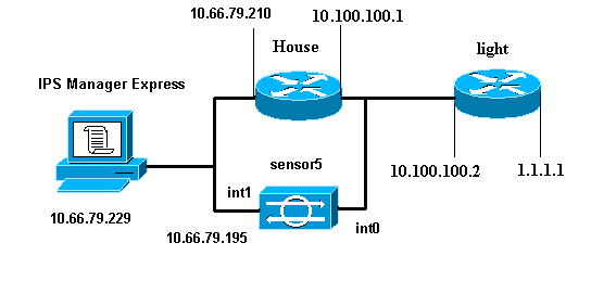
このドキュメントでは、次の図で示されるネットワーク設定を使用しています。
設定
このドキュメントでは、次に示す設定を使用しています。
| Router Light |
|---|
Current configuration : 906 bytes ! version 12.4 service timestamps debug uptime service timestamps log uptime no service password-encryption ! hostname light ! enable password cisco ! username cisco password 0 cisco ip subnet-zero ! ! ! ip ssh time-out 120 ip ssh authentication-retries 3 ! call rsvp-sync ! ! ! fax interface-type modem mta receive maximum-recipients 0 ! controller E1 2/0 ! ! ! interface FastEthernet0/0 ip address 10.100.100.2 255.255.255.0 duplex auto speed auto ! interface FastEthernet0/1 ip address 1.1.1.1 255.255.255.0 duplex auto speed auto ! interface BRI4/0 no ip address shutdown ! interface BRI4/1 no ip address shutdown ! interface BRI4/2 no ip address shutdown ! interface BRI4/3 no ip address shutdown ! ip classless ip route 0.0.0.0 0.0.0.0 10.100.100.1 ip http server ip pim bidir-enable ! ! dial-peer cor custom ! ! line con 0 line 97 108 line aux 0 line vty 0 4 login ! end |
| Router House |
|---|
Current configuration : 939 bytes ! version 12.4 service timestamps debug uptime service timestamps log uptime no service password-encryption ! hostname house ! logging queue-limit 100 enable password cisco ! ip subnet-zero ! ! no ip cef no ip domain lookup ! ip audit notify log ip audit po max-events 100 ! ! no voice hpi capture buffer no voice hpi capture destination ! ! ! ! interface FastEthernet0/0 ip address 10.66.79.210 255.255.255.224 duplex auto speed auto ! interface FastEthernet0/1 ip address 10.100.100.1 255.255.255.0 duplex auto speed auto ! interface ATM1/0 no ip address shutdown no atm ilmi-keepalive ! ip classless ip route 0.0.0.0 0.0.0.0 10.66.79.193 ip route 1.1.1.0 255.255.255.0 10.100.100.2 no ip http server no ip http secure-server ! ! ! ! call rsvp-sync ! ! mgcp profile default ! ! line con 0 exec-timeout 0 0 line aux 0 line vty 0 4 exec-timeout 0 0 password cisco login line vty 5 15 login ! ! end |
センサー設定の開始
センサーの設定を開始するには、次の手順を実行します。
-
センサーに初めてログインする場合は、ユーザー名としてcisco、パスワードとしてciscoを入力します。
-
システムがパスワード変更のプロンプトを表示したら、パスワードを変更します。
注:Cisco123は辞書語であり、システムでは使用できません。
-
setupと入力し、システムプロンプトを完了して、センサーの基本的なパラメータを設定します。
-
次の情報を入力します。
sensor5#setup --- System Configuration Dialog --- !--- At any point you may enter a question mark '?' for help. !--- Use ctrl-c to abort the configuration dialog at any prompt. !--- Default settings are in square brackets '[]'. Current Configuration: networkParams ipAddress 10.66.79.195 netmask 255.255.255.224 defaultGateway 10.66.79.193 hostname Corp-IPS telnetOption enabled !--- Permit the IP address of workstation or network with IME accessList ipAddress 10.66.79.0 netmask 255.255.255.0 exit timeParams summerTimeParams active-selection none exit exit service webServer general ports 443 exit exit -
設定を保存します。
センサーが設定を保存するのに数分かかることがあります。
[0] Go to the command prompt without saving this config.
[1] Return back to the setup without saving this config.
[2] Save this configuration and exit setup.

Enter your selection[2]: 2
IMEへのセンサーの追加
センサーをIMEに追加するには、次の手順を実行します。
-
IPS Manager ExpressをインストールしたWindows PCに移動し、IPS Manager Expressを開きます。
-
「ホーム」>「追加」を選択します。
-
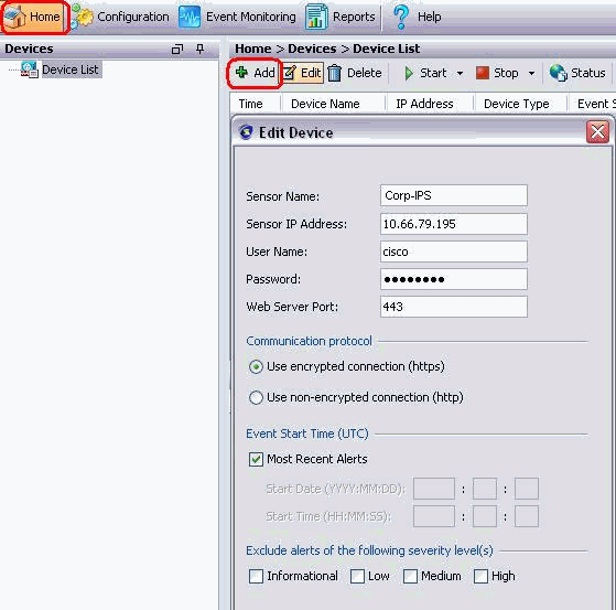
この情報を入力し、[OK]をクリックして設定を終了します。
-
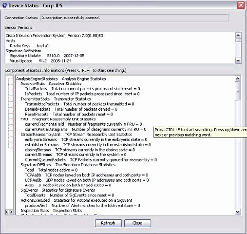
[Devices] > [Corp-IPS]の順に選択し、センサーのステータスを確認してから、右クリックして[Device Status]を選択します。
「Subscription successfully opened」と表示されていることを確認してください。
Cisco IOSルータのTCP Resetの設定
Cisco IOSルータのTCP Resetを設定するには、次の手順を実行します。
-
IME PCからWebブラウザを開き、https://10.66.79.195に移動します。
-
[OK]をクリックして、センサーからダウンロードしたHTTPS証明書を受け入れます。
-
Login ウィンドウで、ユーザ名に cisco、パスワードに 123cisco123 を入力します。
次のIME管理インターフェイスが表示されます。
-
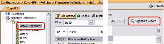
[構成]タブで、[アクティブな署名]をクリックします。
-
次に、[署名ウィザード]をクリックします。
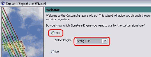
-
ウィザードで、[はい]を選択し、シグニチャエンジンとして[文字列TCP]を選択します。[next] をクリックします。
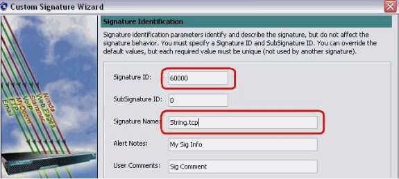
-
この情報はデフォルトのままにするか、独自のシグニチャID、シグニチャ名、およびユーザノートを入力できます。[next] をクリックします。
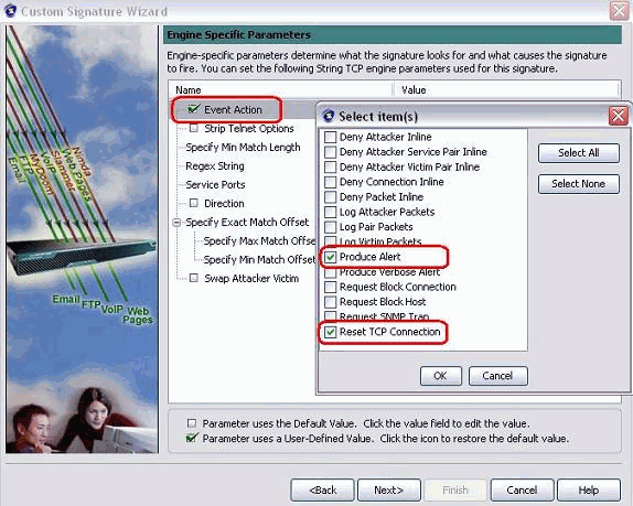
-
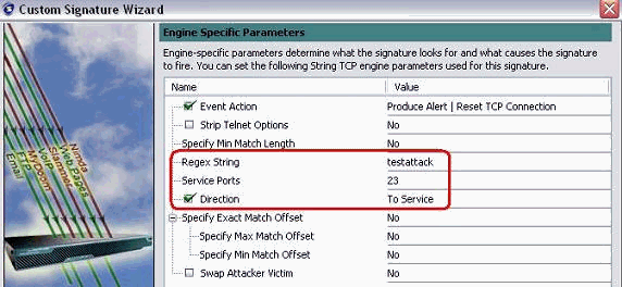
[Event Action]を選択し、[Produce Alert]および[Reset TCP Connection]を選択します。[OK]をクリックし、[Next]をクリックして続行します。
-
正規表現を入力し、この例でtestattackを使用します。[Service Ports]に23と入力し、[Direction]に[To Service]を選択し、[Next]をクリックして続行します。
-
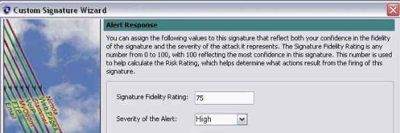
この情報は[Default]のままにします。[next] をクリックします。
-
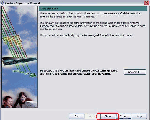
[Finish]をクリックして、ウィザードを終了します。
-
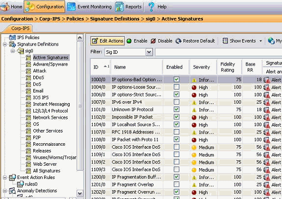
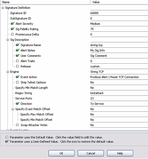
[Configuration] > [sig0] > [Active Signatures]の順に選択して、[Sig ID]または[Sig Name]を使用して新しく作成されたシグニチャを見つけます。[Edit]をクリックし、シグニチャを表示します。
-
確認した後[OK]をクリックし、[Apply]ボタンをクリックしてシグニチャをセンサーに適用します。
確認
攻撃とTCPリセットの起動
攻撃とTCPリセットを開始するには、次の手順を実行します。
-
攻撃を開始する前に、IMEに移動し、[Event Monitoring] > [Dropped Attacks View]を選択し、右側のセンサーを選択します。
-
Router Light から Router House に Telnet 接続し、testattack と入力します。
<space>または<enter>を押して、Telnetセッションをリセットします。
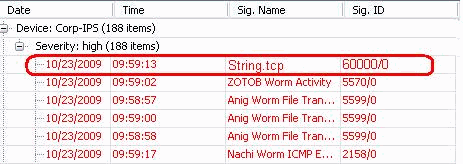
light#telnet 10.100.100.1 Trying 10.100.100.1 ... Open User Access Verification Password: house>en Password: house#testattack [Connection to 10.100.100.1 closed by foreign host] !--- Telnet session has been reset due to the !--- signature "String.tcp" triggered. -
IPS Event Viewerのダッシュボードから、攻撃が開始されるとRed Alarmが表示されます。
トラブルシュート
ここでは、設定のトラブルシューティングに使用できる情報を示します。
ヒント
次のトラブルシューティングのヒントを使用します。
-
コマンドおよびコントロール ポートからシャニング(排除機能)を実行すると、ルータの access control list(ACL; アクセス コントロール リスト)が再プログラムされます。 TCP Reset は、Sensor のスニフィング インターフェイスから送信されます。スイッチでspanを設定すると、次に示すようにset span <src_mod/src_port><dest_mod/dest_port>コマンドを使用し、両方の着信パケットを有効にします。
banana (enable)set span 2/12 3/6 both inpkts enable
Overwrote Port 3/6 to monitor transmit/receive traffic of Port 2/12
Incoming Packets enabled. Learning enabled. Multicast enabled.
banana (enable)
banana (enable)
banana (enable)show span

Destination     : Port 3/6
!--- connect to sniffing interface of the sensor
Admin Source    : Port 2/12
!--- connect to FastEthernet0/0 of Router House
Oper Source     : Port 2/12
Direction       : transmit/receive
Incoming Packets: enabled
Multicast       : enabled
-
TCP Reset が動作している場合は、アクション タイプ TCP Reset に対してアラームがトリガされるかどうかを確認してください。アラームが表示されたら、シグニチャタイプがTCP resetに設定されていることを確認します。
サービスアカウントsuを使用してrootでログインし、このコマンドを発行します。このコマンドは、センシングインターフェイスがeth0に設定されていることを前提としています。
[root@sensor1 root]#tcpdump -i eth0 -n
注:100個のTCPリセットが標的/標的に送信され、100個のTCPリセットが攻撃者/クライアントに送信されます。
次に出力例を示します。
03:06:00.598777 64.104.209.205.1409 >
 10.66.79.38.telnet: R 107:107(0) ack 72 win 0
03:06:00.598794 64.104.209.205.1409 >
 10.66.79.38.telnet: R 108:108(0) ack 72 win 0

03:06:00.599360 10.66.79.38.telnet >
 64.104.209.205.1409: R 72:72(0) ack 46 win 0
03:06:00.599377 10.66.79.38.telnet >
 64.104.209.205.1409: R 73:73(0) ack 46 win 0
関連情報
更新履歴
| 改定 | 発行日 | コメント |
|---|---|---|
1.0 |
08-Dec-2009 |
初版 |
 フィードバック