Cisco Secure Services Client Administrator Guide, Release 5.0
Bias-Free Language
The documentation set for this product strives to use bias-free language. For the purposes of this documentation set, bias-free is defined as language that does not imply discrimination based on age, disability, gender, racial identity, ethnic identity, sexual orientation, socioeconomic status, and intersectionality. Exceptions may be present in the documentation due to language that is hardcoded in the user interfaces of the product software, language used based on RFP documentation, or language that is used by a referenced third-party product. Learn more about how Cisco is using Inclusive Language.
- Updated:
- August 17, 2007
Chapter: Deployment Example Using the SSC Management Utility GUI
Deployment Example Using the SSC Management Utility GUI
This chapter provides a deployment example that illustrates how to use the Cisco SSC Management Utility to create an enterprise-specific distribution package. This chapter contains this section:
•![]() SSC Management Utility GUI Deployment Example
SSC Management Utility GUI Deployment Example
SSC Management Utility GUI Deployment Example
Before you begin using the SSC management utility, remember these points:
•![]() You can click on the ? symbol next to an entry to obtain context-sensitive help.
You can click on the ? symbol next to an entry to obtain context-sensitive help.
•![]() The page that displays when you click Next is determined by the choices you made on the current page.
The page that displays when you click Next is determined by the choices you made on the current page.
The following steps illustrate how to create an enterprise-specific distribution package using the GUI:
Step 1 ![]() Click sscManagementUtility.exe and the welcome page displays (see Figure 2-1).
Click sscManagementUtility.exe and the welcome page displays (see Figure 2-1).
Figure 2-1 SSC Management Utility Welcome Page
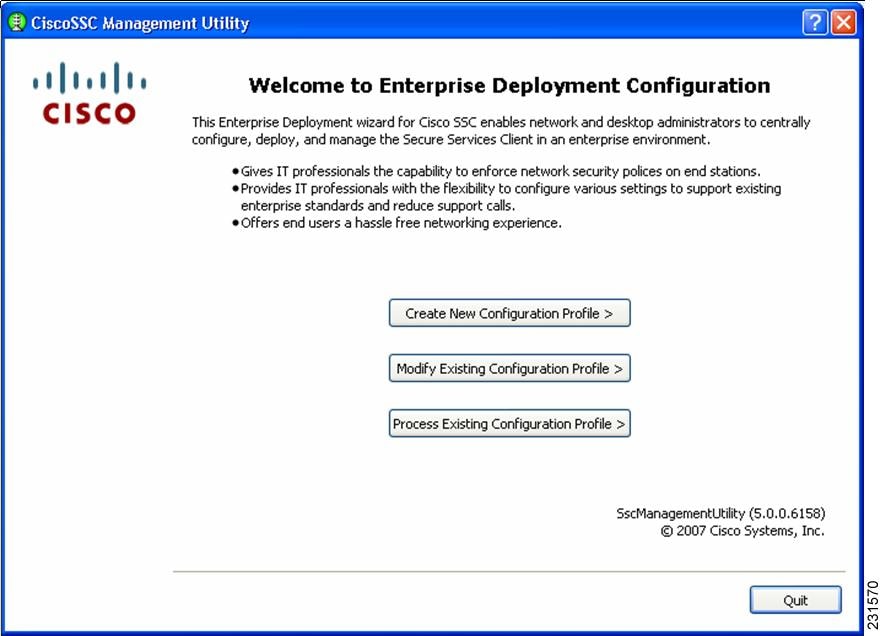
There are three choices on this page:
•![]() Create New Configuration Profile—allows you to create a new deployment profile from scratch.
Create New Configuration Profile—allows you to create a new deployment profile from scratch.
•![]() Modify Existing Configuration Profile—allows you to modify an already created (unprocessed) deployment file.
Modify Existing Configuration Profile—allows you to modify an already created (unprocessed) deployment file.
•![]() Process Existing Configuration Profile—allows you to process an existing unprocessed deployment file. Processing involves these operations:
Process Existing Configuration Profile—allows you to process an existing unprocessed deployment file. Processing involves these operations:
–![]() Encrypt credentials and other secrets in the file
Encrypt credentials and other secrets in the file
–![]() Pulls in the CA certificates and PAC files that are specified in the file.
Pulls in the CA certificates and PAC files that are specified in the file.
–![]() Signs the resulting file, so that end-users are prevented from tampering with the administrator deployed configuration file.
Signs the resulting file, so that end-users are prevented from tampering with the administrator deployed configuration file.
Step 2 ![]() To create a new configuration file from scratch, click Create New Configuration Profile and Figure 2-2 displays.
To create a new configuration file from scratch, click Create New Configuration Profile and Figure 2-2 displays.
Figure 2-2 Select Cisco SCS Version Page
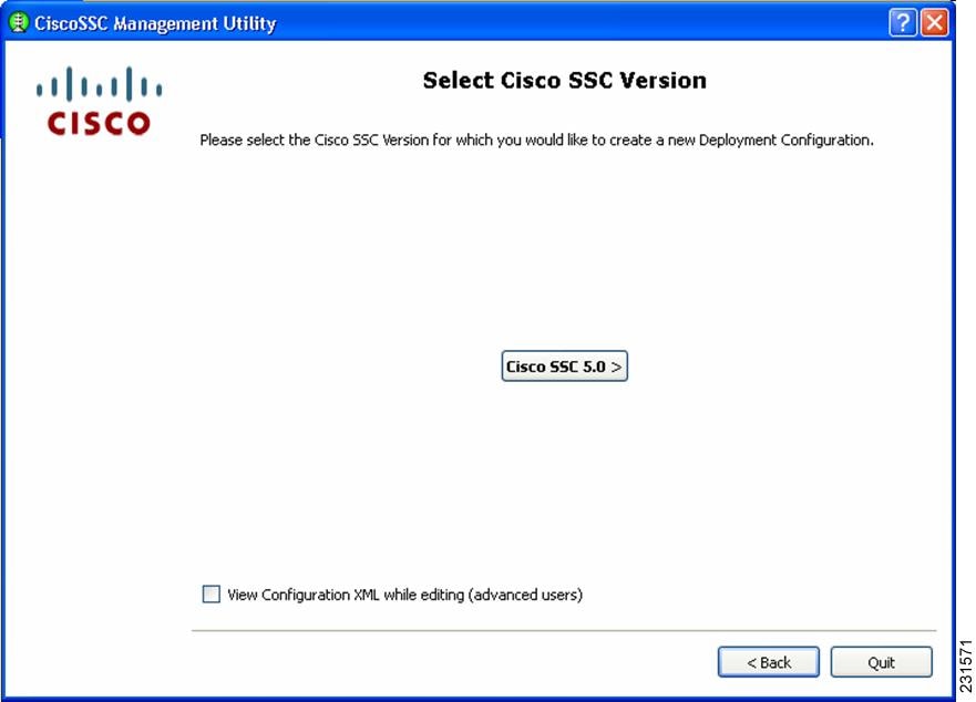
The SSC management utility enables you to create a configuration file for Cisco SSC releases 5.0, 4.1 and 4.2 (only SCS 5.0 is shown in this illustration).
Step 3 ![]() Click Cisco SSC 5.0 and the Client Policy (Figure 2-3) displays.
Click Cisco SSC 5.0 and the Client Policy (Figure 2-3) displays.
Figure 2-3 Cisco Policy Page
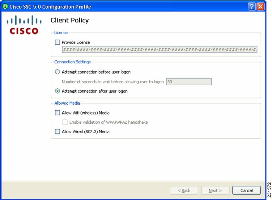

Note ![]() Cisco SSC release 5.0 does not allow end-users to enter license numbers using the GUI. It is the responsibility of the enterprise administrator to create a distribution package that contains a valid license, so that all end-users have the appropriate licenses.
Cisco SSC release 5.0 does not allow end-users to enter license numbers using the GUI. It is the responsibility of the enterprise administrator to create a distribution package that contains a valid license, so that all end-users have the appropriate licenses.
There are two sections on this page:
•![]() Connection Settings section—allows you to define whether 802.1x authentication must be attempted before Windows domain authentication, i.e. pre-logon. In the case of pre-logon, you can also specify how long to wait for the connection. If a network connection cannot be established within this time, the Windows logon process continues with user logon.
Connection Settings section—allows you to define whether 802.1x authentication must be attempted before Windows domain authentication, i.e. pre-logon. In the case of pre-logon, you can also specify how long to wait for the connection. If a network connection cannot be established within this time, the Windows logon process continues with user logon.
•![]() Allowed Media section—enables the types of media controlled by the Cisco SSC client.
Allowed Media section—enables the types of media controlled by the Cisco SSC client.
Note ![]() Cisco SSC release 5.0 is single-homed, it allows only one network connection at a time. Also wired connections are prioritized higher than wireless connections.
Cisco SSC release 5.0 is single-homed, it allows only one network connection at a time. Also wired connections are prioritized higher than wireless connections.
If wireless media is allowed, you can either enable or disable WPA/WPA2 handshake validation.
Step 4 ![]() Choose the desired options on this page and click Next. Figure 2-4 displays.
Choose the desired options on this page and click Next. Figure 2-4 displays.
Figure 2-4 Authentication Policy Page
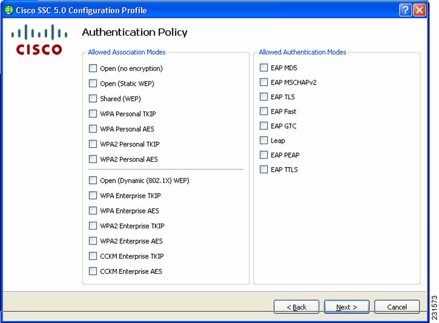
This screen allows you to define network policies - these policies are global. Global policies apply to all networks that you, the administrator, or the user can create.
Step 5 ![]() Choose the desired network policy options and click Next.The Networks page (Figure 2-5) displays.
Choose the desired network policy options and click Next.The Networks page (Figure 2-5) displays.
Figure 2-5 Networks Page
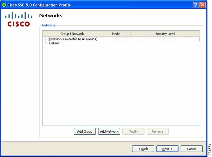
This screen allows you to configure networks that are pre-define for your enterprise. You can either configure networks that are available across all groups or create groups with specific networks. For additional information on groups, refer to the "Distribution Package" section on page 1-2.
Step 6 ![]() To begin creating a group, click Add Group and the User Group page (Figure 2-6) displays.
To begin creating a group, click Add Group and the User Group page (Figure 2-6) displays.
Figure 2-6 Add Group Page
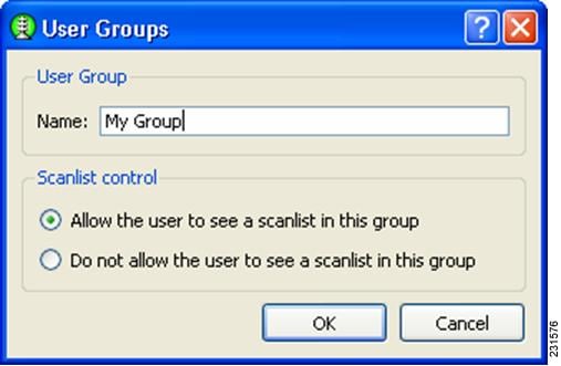
Scan list control— enables you to control whether users can see the scanlist when this group active. There are situations when it might necessary to not allow users to view the scan list, for example, if it is necessary to exclude nearby wireless devices that end-users should not accidentally connect to their networks.
Note ![]() This is a per-group setting. For groups created by the end-user using the GUI, the scan list control is set to Allow the user to see a scan list in this group.
This is a per-group setting. For groups created by the end-user using the GUI, the scan list control is set to Allow the user to see a scan list in this group.
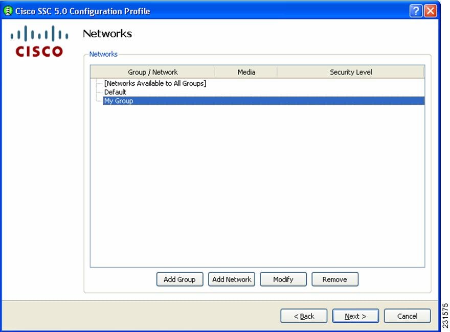
Step 7 ![]() Enter the User Group Name and choose the desired scan list control options. When complete, click OK and the Networks page redisplays with the new group just created (My Group in this example) visible.
Enter the User Group Name and choose the desired scan list control options. When complete, click OK and the Networks page redisplays with the new group just created (My Group in this example) visible.
Figure 2-7 Network Page with New Group Visible
Step 8 ![]() To add a network to a newly created group (My Group in this example), click My Group to highlight it and click Add Network. The Network Media page (Figure 2-8) displays.
To add a network to a newly created group (My Group in this example), click My Group to highlight it and click Add Network. The Network Media page (Figure 2-8) displays.
Figure 2-8 Network Media Page
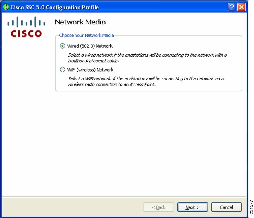
Step 9 ![]() This page enables you to choose whether you want to add a wired or a wireless network. In this example, choose Wifi (wireless) Network to add a wireless network and click Next. The WiFi Network Setting page (Figure 2-9) displays.
This page enables you to choose whether you want to add a wired or a wireless network. In this example, choose Wifi (wireless) Network to add a wireless network and click Next. The WiFi Network Setting page (Figure 2-9) displays.
Figure 2-9 WiFi Network Settings Page
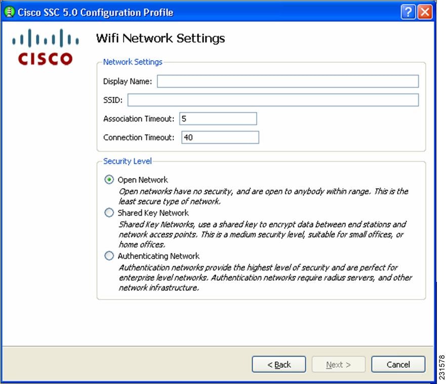
Step 10 ![]() This page enables you to create an open (non-secure) network, a shared key network, or an 802.1x authentication network.
This page enables you to create an open (non-secure) network, a shared key network, or an 802.1x authentication network.
Step 11 ![]() Enter the network name in the Display Name field.
Enter the network name in the Display Name field.
Step 12 ![]() In the SSID field, enter the ssid you want to associate to.
In the SSID field, enter the ssid you want to associate to.
Step 13 ![]() Choose a network type, in this example, click Open Network.
Choose a network type, in this example, click Open Network.
The AssociationTimeout value is the time that the Cisco SSC client waits for association to the ssid before it tries another network.
The Connection Timeout value is the time that the Cisco SSC client waits for a network connection to be established, before it tries another network.
Network connection is considered established if the Cisco SSC client obtains an IP address for that network.
Step 14 ![]() Click Next and the 802.1x connection settings page displays:
Click Next and the 802.1x connection settings page displays:
Figure 2-10 802.1X Connection Setting Page
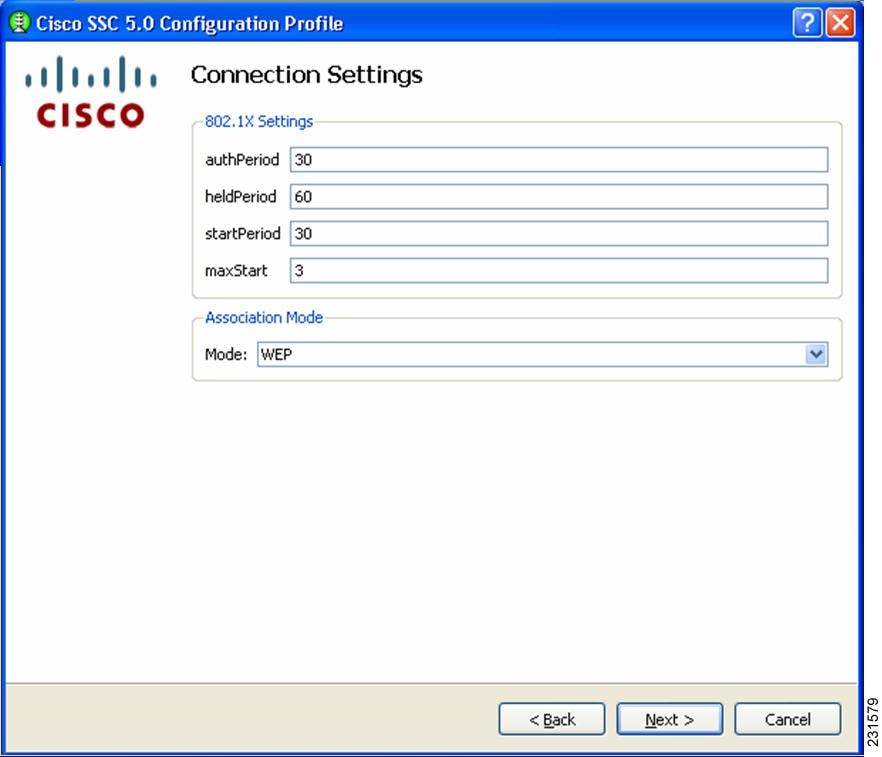
This screen enables you to enter your 802.1x timer values. The default values should work for most networks, however, you have the option to set it to suit your environment.
Step 15 ![]() Enter the desired 802.1x timer values. In this example, choose to accept the default values.
Enter the desired 802.1x timer values. In this example, choose to accept the default values.
Step 16 ![]() Choose the association mode for this network, by clicking the drop-down arrow. In this example, choose WEP.
Choose the association mode for this network, by clicking the drop-down arrow. In this example, choose WEP.
Step 17 ![]() Click Next and the Network Connection Type page (Figure 2-11) displays:
Click Next and the Network Connection Type page (Figure 2-11) displays:
Figure 2-11 Network Connection Type Page
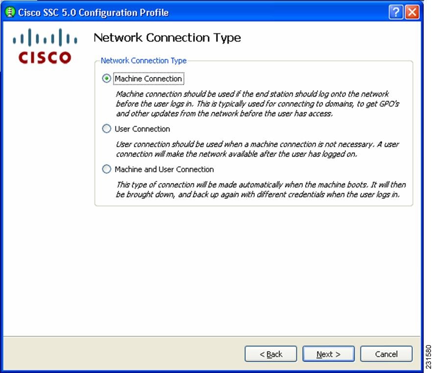
This page enables you to choose the type of network connection. The SSC client defaults to Machine Connection. The User Connections are attempted only during a user session.
A Machine-User ' network contains a machine part and a user part. The ssid is the same for the two parts, but the credential type for machine connection can be different from the credential type for user connection.
Step 18 ![]() In this example, choose Machine and User Connection.
In this example, choose Machine and User Connection.
Step 19 ![]() Click Next and the Machine Authentication Method page ( Figure 2-12) displays.
Click Next and the Machine Authentication Method page ( Figure 2-12) displays.
Figure 2-12 Machine Authentication Method Page
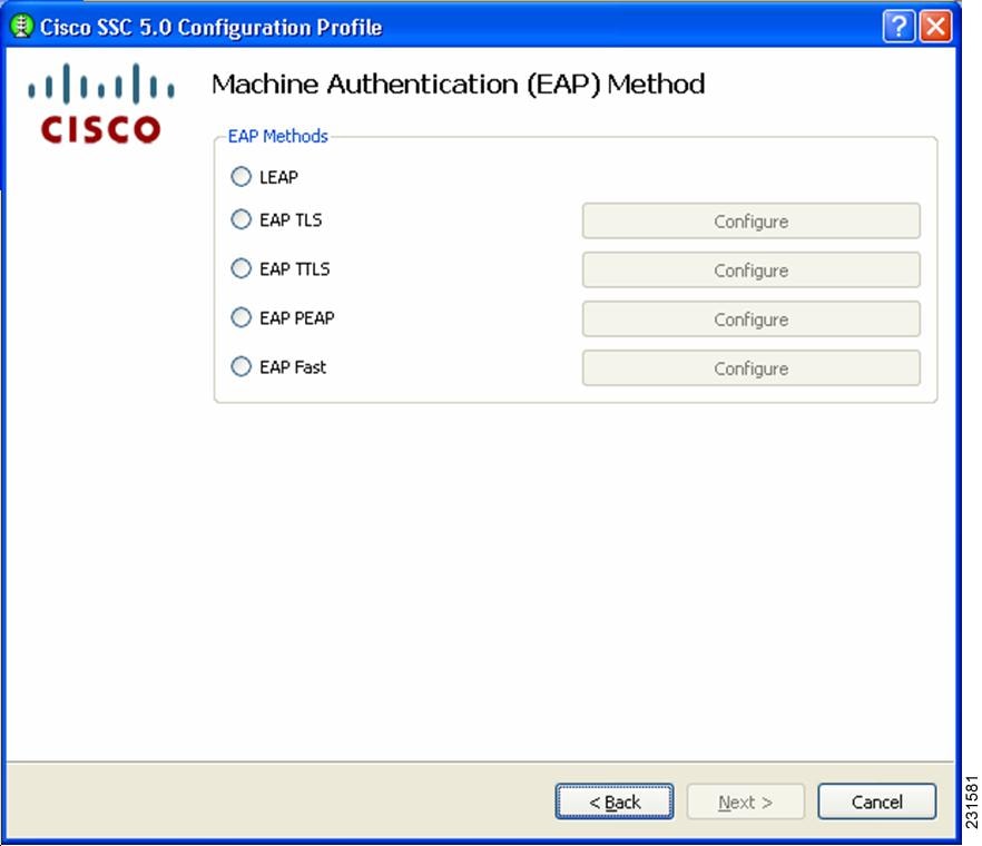
This page enables you to choose the machine authentication method.
Step 20 ![]() In this example, to create a Peap-MSChapv2 network, check EAP PEAP.
In this example, to create a Peap-MSChapv2 network, check EAP PEAP.
Step 21 ![]() To configure PEAP settings, click Configure next to EAP PEAP. The EAP Peap Setting page (Figure 2-13) displays.
To configure PEAP settings, click Configure next to EAP PEAP. The EAP Peap Setting page (Figure 2-13) displays.
Figure 2-13 EAP PEAP Setting Page
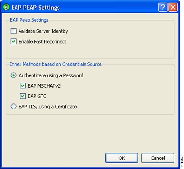
This page enables you to specify these options:
•![]() Validate Server Identity—enables server certificate validation.
Validate Server Identity—enables server certificate validation.
•![]() Enable Fast Reconnect—enables session resumption.
Enable Fast Reconnect—enables session resumption.
•![]() Inner methods based on Credentials Source—enables you to choose authenticate using a password or a certificate.
Inner methods based on Credentials Source—enables you to choose authenticate using a password or a certificate.
Step 22 ![]() Choose the desired options and click OK to return to the Machine Authentication Method (Figure 2-12) page.
Choose the desired options and click OK to return to the Machine Authentication Method (Figure 2-12) page.
Step 23 ![]() Click Next and the Machine Credentials page (Figure 2-14) displays.
Click Next and the Machine Credentials page (Figure 2-14) displays.
Figure 2-14 Machine Credentials Page
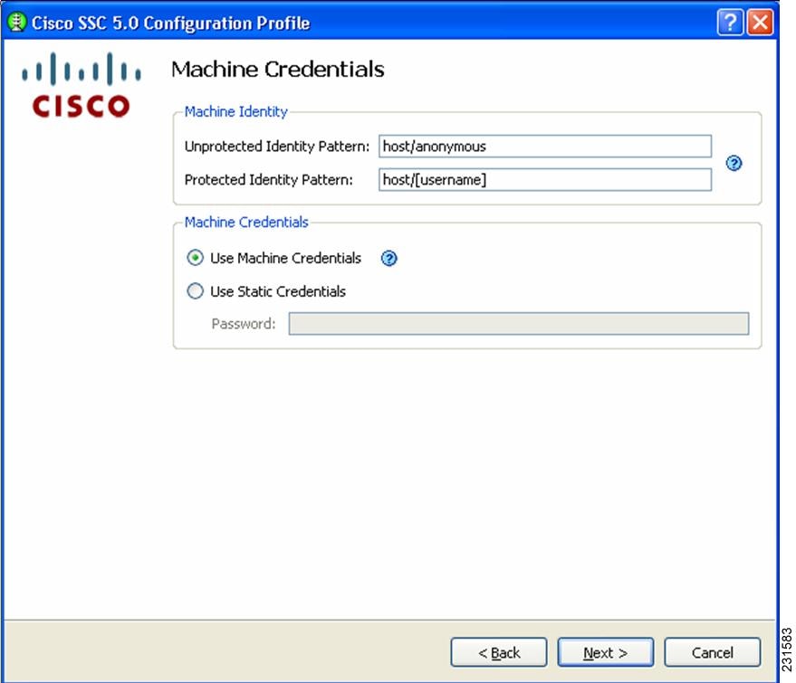
This page enables you to specify the credentials to use to establish this network.
Cisco SSC release 5.0 supports these placeholder patterns when specifying identities:
•![]() [username]
[username]
•![]() [domain]
[domain]
When the [username] and/or [domain] placeholders are used then these conditions apply:
•![]() If a client certificate is used for authentication, then the placeholder's values is obtained from the CN field of the client certificate.
If a client certificate is used for authentication, then the placeholder's values is obtained from the CN field of the client certificate.
•![]() Otherwise, the credentials are obtained from the operating system and the [username] placeholder represents the assigned machine name.
Otherwise, the credentials are obtained from the operating system and the [username] placeholder represents the assigned machine name.
A typical pattern for machine unprotected identity is host\anonymous.[domain].
–![]() If password source is this configured for this profile, then the pattern would be the actual string to send as the username with no placeholders.
If password source is this configured for this profile, then the pattern would be the actual string to send as the username with no placeholders.
A typical pattern for machine protected identity is host\[username].[domain].
–![]() If password source is configured for this profile, then the pattern would be the actual string to send as the username.
If password source is configured for this profile, then the pattern would be the actual string to send as the username.
Step 24 ![]() Enter the desired settings for the machine connection and click Next. The User Authentication Method page (Figure 2-15) displays again.
Enter the desired settings for the machine connection and click Next. The User Authentication Method page (Figure 2-15) displays again.
Figure 2-15 User Authentication Method Page
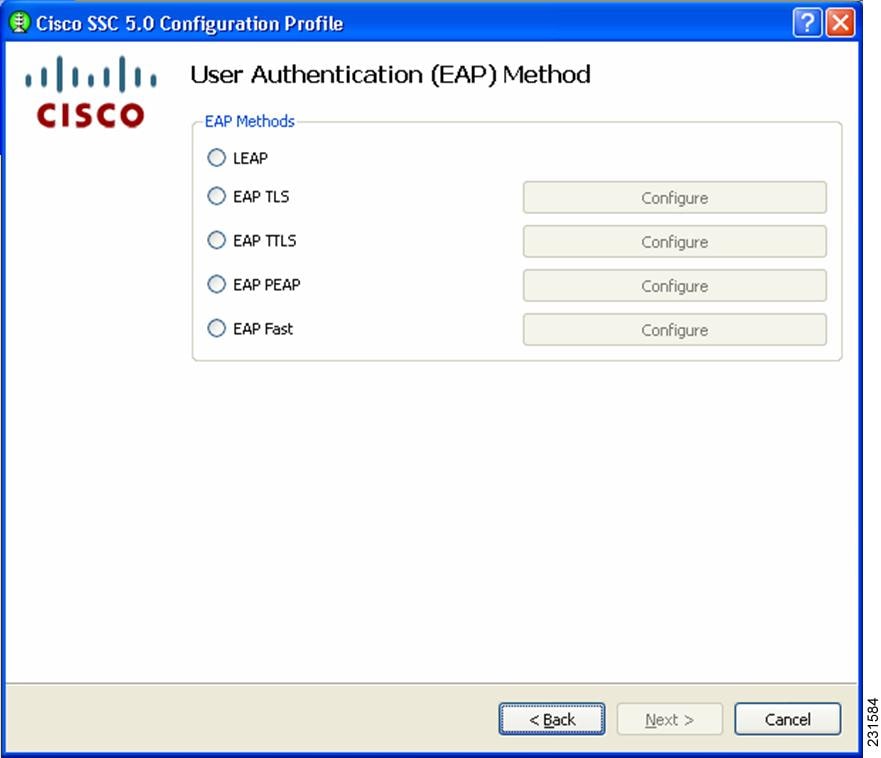
Now you need to specify the credentials for the machine connection.
Step 25 ![]() In this example for user authentication, check EAP Fast and click Configure next EAP-Fast. The EAP Fast Settings page (Figure 2-16) displays.
In this example for user authentication, check EAP Fast and click Configure next EAP-Fast. The EAP Fast Settings page (Figure 2-16) displays.
Figure 2-16 EAP Fast Settings Page
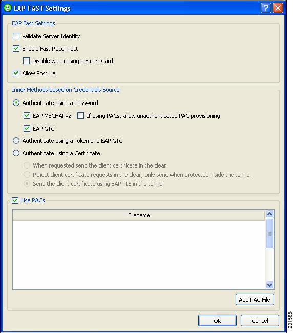
On this page, you have the option to include a manually provisioned PAC by clicking Add PAC File. The contents of the PAC file is added to the distribution package, producing a single deployment file.
Step 26 ![]() In this example, check the EAP Fast options shown in Figure 2-16 and click OK. The User Authentication Method page (Figure 2-15) displays again.
In this example, check the EAP Fast options shown in Figure 2-16 and click OK. The User Authentication Method page (Figure 2-15) displays again.
Step 27 ![]() Click Next to configure the user credentials. The User Credentials page (Figure 2-17) displays.
Click Next to configure the user credentials. The User Credentials page (Figure 2-17) displays.
Figure 2-17 User Credentials Page
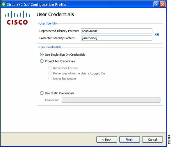
This page enables you to specify the credentials to use to establish this network.
Cisco SSC release 5.0 supports these placeholder patterns when specifying user identities:
•![]() [username]
[username]
•![]() [domain]
[domain]
When the [username] and/or [domain] placeholders are used then these conditions apply:
•![]() If a client certificate is used for authentication, then the placeholder's values is obtained from the CN field of the client certificate.
If a client certificate is used for authentication, then the placeholder's values is obtained from the CN field of the client certificate.
–![]() If the credential source is the end-user, then the placeholder's values is obtained from the information the user enters.
If the credential source is the end-user, then the placeholder's values is obtained from the information the user enters.
–![]() If the credentials are obtained from the operating system, then the placeholder's value is obtained from the logon information.
If the credentials are obtained from the operating system, then the placeholder's value is obtained from the logon information.
A typical pattern for user unprotected identity is anonymous@[domain] for tunneled methods or [username]@[domain] for non-tunneled methods.
If the credential source is this profile, then the pattern would be the actual string to send as the username (no placeholders). A typical pattern for user protected identity is [username]@[domain].
If the password source is this profile, then the pattern would be the actual string to send as the username (no placeholders).
When you have specified the identity pattern, you can then specify the credential source. You can either prompt the user for credentials or use single signon credentials (the SSC client obtains these from the operating system) or specify the actual credentials to be sent in the deployment file.
When you have completed your selections, click on Finish. You have finished creating a network.
Now you can add as many networks as needed and when done, click on Next.
At this point, the management tool validates the networks you have defined against your policy settings. If there are any policy violations with the networks you have just created, they are displayed. If errors are indicated, you must fix them before you can save the file. For example, this Validation page might (Figure 2-18) display.
Figure 2-18 Validation Page
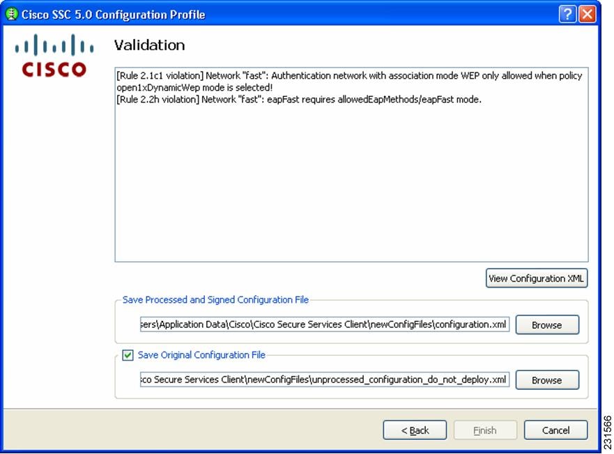
When there are no validation errors, you can choose to save the deployment file. The management utility saves two formats of the deployment file in any location you choose. The processed file (with encrypted credentials, PACs and CA certificates and signed) is stored by default in this file location:
C:\Documents and Settings\All Users\Application Data\Cisco\
Cisco Secure Services Client\newConfigFiles\configuration.xml
The Cisco SSC client looks in this location for any new distribution package. If you have the client installed on your system, this also allows you to automatically test the configuration that you just created and verify it before deploying it.
The unprocessed deployment file is saved in this location:
C:\Documents and Settings\All Users\Application Data\Cisco\Cisco Secure Services Client\
newConfigFiles\unprocessed_configuration_do_not_deploy.xml

If you need to make changes to the deployment package you just created, you can reopen the management utility and click on Modify Existing Configuration on the welcome page (Figure 2-1) and choose the unprocessed deployment file that you just saved.
 Feedback