- Preface
- Chapter 1 - Product Overview
- Chapter 2 - Preparing for Installation
- Chapter 3 - Installing the Client Adapter
- Chapter 4 - Using the Profile Manager
- Chapter 5 - Configuring the Client Adapter
- Chapter 6 - Using EAP Authentication
- Chapter 7 - Viewing Status and Statistics
- Chapter 8 - Using the Aironet System Tray Utility (ASTU)
- Chapter 9 - Routine Procedures
- Chapter 10 - Troubleshooting
- Appendix A - Technical Specifications
- Appendix B - Translated Safety Warnings
- Appendix C - Declarations of Conformity and Regulatory Information
- Appendix D - Channels, Power Levels, and Antenna Gains
- Appendix E - Configuring the Client Adapter through the Windows XP Operating System
- Glossary
- Index
Cisco Aironet 802.11a/b/g Wireless LAN Client Adapters (CB21AG and PI21AG) Installation and Configuration Guide, OL-4211-02
Bias-Free Language
The documentation set for this product strives to use bias-free language. For the purposes of this documentation set, bias-free is defined as language that does not imply discrimination based on age, disability, gender, racial identity, ethnic identity, sexual orientation, socioeconomic status, and intersectionality. Exceptions may be present in the documentation due to language that is hardcoded in the user interfaces of the product software, language used based on RFP documentation, or language that is used by a referenced third-party product. Learn more about how Cisco is using Inclusive Language.
- Updated:
- June 29, 2007
Chapter: Chapter 3 - Installing the Client Adapter
Installing the Client Adapter
This chapter provides instructions for installing the client adapter.
The following topics are covered in this chapter:
•![]() Installing the Client Adapter Software
Installing the Client Adapter Software
Installing the Client Adapter Software
This section describes how to install Cisco Aironet CB21AG or PI21AG client adapter drivers and utilities from a single executable file named Win-Client-802.11a-b-g-Ins-Wizard-vx.exe, where x represents the release number. Follow these steps to install these client adapter software components on a computer running Windows 2000 or XP.


Note ![]() This procedure is meant to be used the first time the Cisco Aironet CB21AG or PI21AG client adapter software is installed on your computer. If this software is already installed on your computer, follow the instructions in Chapter 9 to upgrade the client adapter software.
This procedure is meant to be used the first time the Cisco Aironet CB21AG or PI21AG client adapter software is installed on your computer. If this software is already installed on your computer, follow the instructions in Chapter 9 to upgrade the client adapter software.
Note ![]() The Install Wizard disables the Microsoft 802.1X supplicant, if installed, to prevent any potential conflicts between ADU and the supplicant.
The Install Wizard disables the Microsoft 802.1X supplicant, if installed, to prevent any potential conflicts between ADU and the supplicant.
Note ![]() Only one wireless client adapter can be installed and used at a time. The software does not support the use of multiple cards.
Only one wireless client adapter can be installed and used at a time. The software does not support the use of multiple cards.
Step 1 ![]() Make sure the client adapter is not inserted in your computer. You will be instructed when to insert it.
Make sure the client adapter is not inserted in your computer. You will be instructed when to insert it.
Step 2 ![]() Use your computer's web browser to access the following URL:
Use your computer's web browser to access the following URL:
http://www.cisco.com/public/sw-center/sw-wireless.shtml
Step 3 ![]() Click Option #2: Aironet Wireless Software Display Tables.
Click Option #2: Aironet Wireless Software Display Tables.
Note ![]() If you prefer to use an automated tool, you can download software from the Software Selector tool instead of the display tables. To do so, click Option #1: Aironet Wireless Software Selector, follow the instructions on the screen, and go to Step 7.
If you prefer to use an automated tool, you can download software from the Software Selector tool instead of the display tables. To do so, click Option #1: Aironet Wireless Software Selector, follow the instructions on the screen, and go to Step 7.
Step 4 ![]() Click Cisco Aironet Wireless LAN Client Adapters.
Click Cisco Aironet Wireless LAN Client Adapters.
Step 5 ![]() Under Aironet Client Adapter Installation Wizard (For Windows), click 802.11a/b/g (CB21AG, PI21AG).
Under Aironet Client Adapter Installation Wizard (For Windows), click 802.11a/b/g (CB21AG, PI21AG).
Step 6 ![]() Click the Install Wizard file with the greatest release number.
Click the Install Wizard file with the greatest release number.
Step 7 ![]() Complete the encryption authorization form; then read and accept the terms and conditions of the Software License Agreement.
Complete the encryption authorization form; then read and accept the terms and conditions of the Software License Agreement.
Step 8 ![]() Click the file again to download it.
Click the file again to download it.
Step 9 ![]() Save the file to your computer's hard drive.
Save the file to your computer's hard drive.
Step 10 ![]() Use Windows Explorer to find the file.
Use Windows Explorer to find the file.
Step 11 ![]() Double-click the file. The "Starting InstallShield Wizard" message appears followed by the Preparing Setup window (see Figure 3-1) and the Cisco Aironet Installation Program window (see Figure 3-2).
Double-click the file. The "Starting InstallShield Wizard" message appears followed by the Preparing Setup window (see Figure 3-1) and the Cisco Aironet Installation Program window (see Figure 3-2).
Figure 3-1 Preparing Setup Window
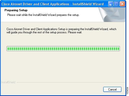
Figure 3-2 Cisco Aironet Installation Program Window

Step 12 ![]() Click Next. The Setup Type window appears (see Figure 3-3).
Click Next. The Setup Type window appears (see Figure 3-3).
Figure 3-3 Setup Type Window
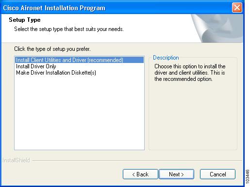
Step 13 ![]() Choose one of the following options:
Choose one of the following options:
Note ![]() To ensure compatibility among software components, Cisco recommends that you install the client utilities and driver.
To ensure compatibility among software components, Cisco recommends that you install the client utilities and driver.
•![]() Install Client Utilities and Driver (recommended)—Installs the client adapter driver and client utilities.
Install Client Utilities and Driver (recommended)—Installs the client adapter driver and client utilities.
•![]() Install Driver Only—Installs only the client adapter driver. If you choose this option, click Next and go to Step 25.
Install Driver Only—Installs only the client adapter driver. If you choose this option, click Next and go to Step 25.
•![]() Make Driver Installation Diskette(s)—Enables you to create driver installation diskettes that can be used to install drivers using the Windows Device Manager.
Make Driver Installation Diskette(s)—Enables you to create driver installation diskettes that can be used to install drivers using the Windows Device Manager.
Step 14 ![]() Click Next.
Click Next.
Step 15 ![]() If a message appears indicating that you are required to restart your computer at the end of the installation process, click Yes.
If a message appears indicating that you are required to restart your computer at the end of the installation process, click Yes.
Note ![]() If you click No, you are asked to confirm your decision. If you proceed, the installation process terminates.
If you click No, you are asked to confirm your decision. If you proceed, the installation process terminates.
The Choose Destination Location window appears (see Figure 3-4).
Figure 3-4 Choose Destination Location Window
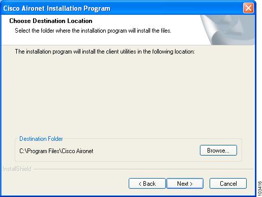
Step 16 ![]() Perform one of the following:
Perform one of the following:
•![]() If you chose the first option in Step 13, click Next to install the client utility files in the C:\Program Files\Cisco Aironet directory.
If you chose the first option in Step 13, click Next to install the client utility files in the C:\Program Files\Cisco Aironet directory.
Note ![]() If you want to install the client utilities in a different directory, click Browse, choose a different directory, click OK, and click Next.
If you want to install the client utilities in a different directory, click Browse, choose a different directory, click OK, and click Next.
•![]() If you chose the Make Driver Installation Diskette(s) option in Step 13, insert a floppy disk into your computer and click Next to copy the driver to the diskette. Go to Step 25.
If you chose the Make Driver Installation Diskette(s) option in Step 13, insert a floppy disk into your computer and click Next to copy the driver to the diskette. Go to Step 25.
Note ![]() If you want to copy the driver to a different drive or directory, click Browse, choose a new location, click OK, and click Next.
If you want to copy the driver to a different drive or directory, click Browse, choose a new location, click OK, and click Next.
Step 17 ![]() The Select Program Folder window appears (see Figure 3-5).
The Select Program Folder window appears (see Figure 3-5).
Figure 3-5 Select Program Folder Window

Step 18 ![]() Click Next to add program icons to the Cisco Aironet program folder.
Click Next to add program icons to the Cisco Aironet program folder.
Note ![]() If you want to specify a different program folder, choose a folder from the Existing Folders list or type a new folder name in the Program Folder field and click Next.
If you want to specify a different program folder, choose a folder from the Existing Folders list or type a new folder name in the Program Folder field and click Next.
Step 19 ![]() If your computer is running Windows 2000, go to Step 25. If your computer is running Windows XP, the IMPORTANT: Please Read! window appears (see Figure 3-6).
If your computer is running Windows 2000, go to Step 25. If your computer is running Windows XP, the IMPORTANT: Please Read! window appears (see Figure 3-6).
Figure 3-6 IMPORTANT: Please Read! Window
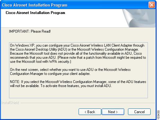
Step 20 ![]() Read the information displayed and click Next. The Choose Configuration Tool window appears (see Figure 3-7).
Read the information displayed and click Next. The Choose Configuration Tool window appears (see Figure 3-7).
Figure 3-7 Choose Configuration Tool Window

Step 21 ![]() Choose one of the following options. Table 3-1 compares the Windows XP and ADU client adapter features.
Choose one of the following options. Table 3-1 compares the Windows XP and ADU client adapter features.
•![]() Cisco Aironet Desktop Utility (ADU)—Enables you to configure your client adapter using ADU.
Cisco Aironet Desktop Utility (ADU)—Enables you to configure your client adapter using ADU.
•![]() Microsoft Wireless Configuration Manager—Enables you to configure your client adapter using the Microsoft Wireless Configuration Manager in Windows XP.
Microsoft Wireless Configuration Manager—Enables you to configure your client adapter using the Microsoft Wireless Configuration Manager in Windows XP.
Note ![]() If you choose Cisco Aironet Desktop Utility (ADU) above, the Microsoft Wireless Configuration Manager is disabled. If you ever manually enable it, you are prompted to disable it whenever ADU is activated.
If you choose Cisco Aironet Desktop Utility (ADU) above, the Microsoft Wireless Configuration Manager is disabled. If you ever manually enable it, you are prompted to disable it whenever ADU is activated.
Step 22 ![]() Click Next.
Click Next.
Step 23 ![]() If you chose Cisco Aironet Desktop Utility (ADU) in Step 21, go to Step 25. If you chose Microsoft Wireless Configuration Manager, the Enable Tray Icon window appears (see Figure 3-8).
If you chose Cisco Aironet Desktop Utility (ADU) in Step 21, go to Step 25. If you chose Microsoft Wireless Configuration Manager, the Enable Tray Icon window appears (see Figure 3-8).
Figure 3-8 Enable Tray Icon Window
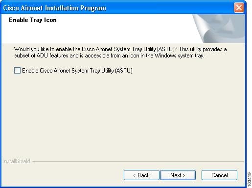
Step 24 ![]() Check the Enable Cisco Aironet System Tray Utility (ASTU) check box if you want to be able to use ASTU even though you have chosen to configure your client adapter through Windows XP instead of ADU and click Next.
Check the Enable Cisco Aironet System Tray Utility (ASTU) check box if you want to be able to use ASTU even though you have chosen to configure your client adapter through Windows XP instead of ADU and click Next.
Step 25 ![]() When prompted to insert your client adapter, perform one of the following:
When prompted to insert your client adapter, perform one of the following:
•![]() If you are using a PC-Cardbus card, insert the card into your computer's Cardbus slot; then click OK. If the Windows Found New Hardware Wizard appears, click Cancel.
If you are using a PC-Cardbus card, insert the card into your computer's Cardbus slot; then click OK. If the Windows Found New Hardware Wizard appears, click Cancel.
Note ![]() Refer to the "Inserting a PC-Cardbus Card" section for instructions on inserting a PC-Cardbus card into your computer.
Refer to the "Inserting a PC-Cardbus Card" section for instructions on inserting a PC-Cardbus card into your computer.
•![]() If you are using a PCI card, click OK. You will insert the card into your computer after you have finished installing the Install Wizard.
If you are using a PCI card, click OK. You will insert the card into your computer after you have finished installing the Install Wizard.
The Setup Status window appears (see Figure 3-9).
Figure 3-9 Setup Status Window

The installation process begins, and you are notified as each software component is installed.
Step 26 ![]() When a message appears indicating that your computer needs to be rebooted, click OK and allow your computer to restart.
When a message appears indicating that your computer needs to be rebooted, click OK and allow your computer to restart.
Step 27 ![]() If you are using a PCI card, insert the card into your computer's PCI slot.
If you are using a PCI card, insert the card into your computer's PCI slot.
Note ![]() Refer to the "Inserting a PCI Card" section for instructions on inserting a PCI card into your computer.
Refer to the "Inserting a PCI Card" section for instructions on inserting a PCI card into your computer.
Step 28 ![]() If the Windows Found New Hardware Wizard appears after your computer reboots, click Next, allow the wizard to install the software for the client adapter, and click Finish.
If the Windows Found New Hardware Wizard appears after your computer reboots, click Next, allow the wizard to install the software for the client adapter, and click Finish.
Step 29 ![]() If your network setup does not include a DHCP server and you plan to use TCP/IP, follow these steps for your operating system.
If your network setup does not include a DHCP server and you plan to use TCP/IP, follow these steps for your operating system.
•![]() Windows 2000
Windows 2000
a. ![]() Double-click My Computer, Control Panel, and Network and Dial-up Connections.
Double-click My Computer, Control Panel, and Network and Dial-up Connections.
b. ![]() Right-click Local Area Connection x (where x represents the number of the connection).
Right-click Local Area Connection x (where x represents the number of the connection).
c. ![]() Click Properties.
Click Properties.
d. ![]() In the Components Checked Are Used by This Connection field, click Internet Protocol (TCP/IP) and Properties.
In the Components Checked Are Used by This Connection field, click Internet Protocol (TCP/IP) and Properties.
e. ![]() Choose Use the following IP address and enter the IP address, subnet mask, and default gateway address of your computer (which can be obtained from your system administrator).
Choose Use the following IP address and enter the IP address, subnet mask, and default gateway address of your computer (which can be obtained from your system administrator).
f. ![]() Click OK to close each open window.
Click OK to close each open window.
•![]() Windows XP
Windows XP
a. ![]() Double-click My Computer, Control Panel, and Network Connections.
Double-click My Computer, Control Panel, and Network Connections.
b. ![]() Right-click Wireless Network Connection x (where x represents the number of the connection).
Right-click Wireless Network Connection x (where x represents the number of the connection).
c. ![]() Click Properties.
Click Properties.
d. ![]() In the This Connection Uses the Following Items field, click Internet Protocol (TCP/IP) and Properties.
In the This Connection Uses the Following Items field, click Internet Protocol (TCP/IP) and Properties.
e. ![]() Choose Use the following IP address and enter the IP address, subnet mask, and default gateway address of your computer (which can be obtained from your system administrator).
Choose Use the following IP address and enter the IP address, subnet mask, and default gateway address of your computer (which can be obtained from your system administrator).
f. ![]() Click OK to close each open window.
Click OK to close each open window.
Step 30 ![]() If you are prompted to restart your computer, click Yes.
If you are prompted to restart your computer, click Yes.
Step 31 ![]() Now that your client adapter is properly installed, it is ready to be configured.
Now that your client adapter is properly installed, it is ready to be configured.
•![]() If you are planning to configure your client adapter through ADU, go to Chapter 4, to create configuration profiles.
If you are planning to configure your client adapter through ADU, go to Chapter 4, to create configuration profiles.
•![]() If you are planning to configure your client adapter through the Windows XP Wireless Configuration Manager, go to Appendix E, .
If you are planning to configure your client adapter through the Windows XP Wireless Configuration Manager, go to Appendix E, .
Note ![]() If you experienced problems during or after installation, refer to Chapter 10 for troubleshooting information.
If you experienced problems during or after installation, refer to Chapter 10 for troubleshooting information.
Inserting a Client Adapter
This section provides instructions for inserting a PC-Cardbus card or PCI card into your computer.
Inserting a PC-Cardbus Card
Step 1 ![]() Before you begin, examine the card. One end has a dual-row, 68-pin connector. The card is keyed so it can be inserted only one way into the Cardbus slot.
Before you begin, examine the card. One end has a dual-row, 68-pin connector. The card is keyed so it can be inserted only one way into the Cardbus slot.
Note ![]() The Cardbus slot is on the left or right side of the computer, depending on the model.
The Cardbus slot is on the left or right side of the computer, depending on the model.
Step 2 ![]() Hold the card with the Cisco label facing up and insert it into the Cardbus slot, applying just enough pressure to make sure it is fully seated (see Figure 3-10). The green LED lights when the card is inserted properly.
Hold the card with the Cisco label facing up and insert it into the Cardbus slot, applying just enough pressure to make sure it is fully seated (see Figure 3-10). The green LED lights when the card is inserted properly.
Figure 3-10
Inserting a PC-Cardbus Card into a Computer
Note ![]() The configuration profiles for PC-Cardbus cards are tied to the slot in which the card is inserted. Therefore, you must always insert your PC-Cardbus card into the same slot or create profiles for both slots. See Chapter 4, for information on creating profiles for your client adapter.
The configuration profiles for PC-Cardbus cards are tied to the slot in which the card is inserted. Therefore, you must always insert your PC-Cardbus card into the same slot or create profiles for both slots. See Chapter 4, for information on creating profiles for your client adapter.
Step 3 ![]() If the Found New Hardware Wizard window appears, click Cancel.
If the Found New Hardware Wizard window appears, click Cancel.
Step 4 ![]() Return to Step 25 of the "Installing the Client Adapter Software" section if you are in the process of installing the client adapter software.
Return to Step 25 of the "Installing the Client Adapter Software" section if you are in the process of installing the client adapter software.
Inserting a PCI Card
You must perform the following procedures in the order listed below to insert a PCI card:
•![]() Change the bracket (if required), see below
Change the bracket (if required), see below
•![]() Insert the card, page 15
Insert the card, page 15
•![]() Assemble the antenna, page 16
Assemble the antenna, page 16
•![]() Mount the antenna, page 17
Mount the antenna, page 17
Changing the Bracket
The PCI card is shipped with a full-profile bracket attached. If the PC into which you are inserting the PCI card requires the card to use a low-profile bracket, follow these steps to change brackets.
Step 1 ![]() Remove the two screws that attach the bracket to the card. See Figure 3-11.
Remove the two screws that attach the bracket to the card. See Figure 3-11.
Figure 3-11 Changing the PCI Card Bracket

|
|
Bracket screws |
Step 2 ![]() Slide the bracket away from the card; then tilt the bracket to free the antenna cable.
Slide the bracket away from the card; then tilt the bracket to free the antenna cable.
Step 3 ![]() Hold the low-profile bracket to the card so that the LEDs slip through their corresponding holes on the bracket.
Hold the low-profile bracket to the card so that the LEDs slip through their corresponding holes on the bracket.
Step 4 ![]() Insert the screws that you removed in Step 1 into the holes on the populated side of the card near the bracket (see Figure 3-11) and tighten.
Insert the screws that you removed in Step 1 into the holes on the populated side of the card near the bracket (see Figure 3-11) and tighten.
Inserting the Card
Follow the steps below to insert a PCI card into your PC.
Step 1 ![]() Turn off the PC and all its components.
Turn off the PC and all its components.
Step 2 ![]() Remove the computer cover.
Remove the computer cover.
Note ![]() On most Pentium PCs, PCI expansion slots are white. Refer to your PC documentation for slot identification.
On most Pentium PCs, PCI expansion slots are white. Refer to your PC documentation for slot identification.
Step 3 ![]() Remove the screw from the top of the CPU back panel above an empty PCI expansion slot. This screw holds the metal bracket on the back panel.
Remove the screw from the top of the CPU back panel above an empty PCI expansion slot. This screw holds the metal bracket on the back panel.
Step 4 ![]() Locate an empty PCI expansion slot inside your computer.
Locate an empty PCI expansion slot inside your computer.
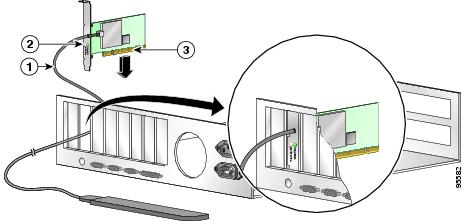
Step 5 ![]() Slip your card's antenna through the opening near the empty expansion slot so that it is located outside of the computer. See Figure 3-12.
Slip your card's antenna through the opening near the empty expansion slot so that it is located outside of the computer. See Figure 3-12.
Figure 3-12 Inserting a PCI Card into a PC
|
|
Antenna cable |
|
|
LEDs |
|
|
Card edge connector |
Step 6 ![]() Tilt the card to enable the LEDs to slip through the opening in the CPU back panel. See the enlarged view in Figure 3-12.
Tilt the card to enable the LEDs to slip through the opening in the CPU back panel. See the enlarged view in Figure 3-12.
Step 7 ![]() Press the card into the empty slot until its connector is firmly seated.
Press the card into the empty slot until its connector is firmly seated.
Step 8 ![]() Reinstall the screw on the CPU back panel and replace the computer cover.
Reinstall the screw on the CPU back panel and replace the computer cover.
Assembling the Antenna
Follow the steps below to assemble the PCI card's antenna.
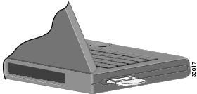
Step 1 ![]() Slide the antenna through the opening in the bottom of the antenna base.
Slide the antenna through the opening in the bottom of the antenna base.
Step 2 ![]() Position the antenna so its notches are facing the Cisco label on the front of the base. See Figure 3-13.
Position the antenna so its notches are facing the Cisco label on the front of the base. See Figure 3-13.
Figure 3-13 Inserting the Antenna into Its Base

|
|
Antenna |
|
|
Notch |
|
|
Antenna base |
Step 3 ![]() Press the antenna cable into the receptacle on the top of the base as shown in Figure 3-13.
Press the antenna cable into the receptacle on the top of the base as shown in Figure 3-13.
Step 4 ![]() Press the antenna straight down into the receptacle until it clicks into place.
Press the antenna straight down into the receptacle until it clicks into place.
Mounting the Antenna
Because the PCI card is a radio device, it is susceptible to RF obstructions and common sources of interference that can reduce throughput and range. Follow these guidelines to ensure the best possible performance:
•![]() Place the PCI card's antenna in an area where large steel structures such as shelving units, bookcases, and filing cabinets will not obstruct radio signals being transmitted or received.
Place the PCI card's antenna in an area where large steel structures such as shelving units, bookcases, and filing cabinets will not obstruct radio signals being transmitted or received.
•![]() Place the antenna away from microwave ovens and 2.4- and 5.8-GHz cordless phones. These products can cause signal interference because they operate in the same frequency range as the PCI card.
Place the antenna away from microwave ovens and 2.4- and 5.8-GHz cordless phones. These products can cause signal interference because they operate in the same frequency range as the PCI card.
Follow the steps below to position the PCI card's antenna on a flat horizontal surface or to mount it to a wall.
Step 1 ![]() Perform one of the following:
Perform one of the following:
•![]() If you want to use the antenna on a flat horizontal surface, position the antenna so it is pointing straight up. Then go to Step 7.
If you want to use the antenna on a flat horizontal surface, position the antenna so it is pointing straight up. Then go to Step 7.
•![]() If you want to mount the antenna to a wall, go to Step 2.
If you want to mount the antenna to a wall, go to Step 2.
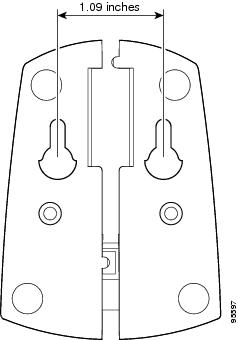
Step 2 ![]() Drill two holes in the wall that are 1.09 in. (2.8 cm) apart. Figure 3-14 shows the distance between the mounting holes on the bottom of the antenna base.
Drill two holes in the wall that are 1.09 in. (2.8 cm) apart. Figure 3-14 shows the distance between the mounting holes on the bottom of the antenna base.
Figure 3-14 Bottom of Antenna Base
Step 3 ![]() Tap the two supplied wall anchors into the holes.
Tap the two supplied wall anchors into the holes.
Step 4 ![]() Drive the two supplied screws into the wall anchors, leaving a small gap between the screw head and the anchor.
Drive the two supplied screws into the wall anchors, leaving a small gap between the screw head and the anchor.
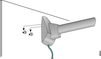
Step 5 ![]() Position the mounting holes on the bottom of the antenna base over the screws (see Figure 3-15) and pull down to lock in place.
Position the mounting holes on the bottom of the antenna base over the screws (see Figure 3-15) and pull down to lock in place.
Figure 3-15 Mounting the Antenna
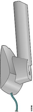
Step 6 ![]() The antenna rotates 90 degrees from its base. For optimal reception, position the antenna so it is pointing straight up (see Figure 3-16).
The antenna rotates 90 degrees from its base. For optimal reception, position the antenna so it is pointing straight up (see Figure 3-16).
Figure 3-16 Rotating the Antenna
Step 7 ![]() Boot up your PC. The green LED lights when the card is inserted properly.
Boot up your PC. The green LED lights when the card is inserted properly.
Step 8 ![]() Go to Step 28 of the "Installing the Client Adapter Software" section if you are in the process of installing the client adapter software.
Go to Step 28 of the "Installing the Client Adapter Software" section if you are in the process of installing the client adapter software.
 Feedback