- Preface
- Chapter 1 - Product Overview
- Chapter 2 - Preparing for Installation
- Chapter 3 - Installing the Client Adapter
- Chapter 4 - Using the Profile Manager
- Chapter 5 - Configuring the Client Adapter
- Chapter 6 - Using EAP Authentication
- Chapter 7 - Performing Diagnostics
- Chapter 8 - Using the Aironet Client Monitor (ACM)
- Chapter 9 - Routine Procedures
- Chapter 10 - Troubleshooting
- Appendix A - Technical Specifications
- Appendix B - Translated Safety Warnings
- Appendix C - Declarations of Conformity and Regulatory Information
- Appendix D - Channels, Power Levels, and Antenna Gains
- Appendix E - Configuring the Client Adapter through Windows XP
- Appendix F - Performing a Site Survey
- Glossary
- Index
Cisco Aironet 340, 350, and CB20A Wireless LAN Client Adapters Installation and Configuration Guide for Windows, OL-1394-05
Bias-Free Language
The documentation set for this product strives to use bias-free language. For the purposes of this documentation set, bias-free is defined as language that does not imply discrimination based on age, disability, gender, racial identity, ethnic identity, sexual orientation, socioeconomic status, and intersectionality. Exceptions may be present in the documentation due to language that is hardcoded in the user interfaces of the product software, language used based on RFP documentation, or language that is used by a referenced third-party product. Learn more about how Cisco is using Inclusive Language.
- Updated:
- May 4, 2007
Chapter: Chapter 5 - Configuring the Client Adapter
- Overview
- Setting System Parameters
- Setting RF Network Parameters
- Setting Advanced Infrastructure Parameters
- Setting Advanced Ad Hoc Parameters
- Setting Network Security Parameters
Configuring the Client Adapter
This chapter explains how to change the configuration parameters for a specific profile.
The following topics are covered in this chapter:
•![]() Setting RF Network Parameters
Setting RF Network Parameters
•![]() Setting Advanced Infrastructure Parameters
Setting Advanced Infrastructure Parameters
•![]() Setting Advanced Ad Hoc Parameters
Setting Advanced Ad Hoc Parameters
•![]() Setting Network Security Parameters
Setting Network Security Parameters
Overview
When you choose to create a new profile or edit an existing profile on the Profile Manager screen, the Properties screens appear with the name of your profile in parentheses. These screens enable you to set the configuration parameters for that profile.

Note ![]() If you do not change any of the configuration parameters, the default values are used.
If you do not change any of the configuration parameters, the default values are used.
Note ![]() If you are planning to set parameters on more than one of the Properties screens, wait until you are finished with all of the screens before clicking OK. When you click OK, you are returned to the Profile Manager screen.
If you are planning to set parameters on more than one of the Properties screens, wait until you are finished with all of the screens before clicking OK. When you click OK, you are returned to the Profile Manager screen.
Each of the Properties screens (listed below) contains parameters that affect a specific aspect of the client adapter:
•![]() System Parameters—Prepares the client adapter for use in a wireless network
System Parameters—Prepares the client adapter for use in a wireless network
•![]() RF Network—Controls how the client adapter transmits and receives data
RF Network—Controls how the client adapter transmits and receives data
•![]() Advanced (Infrastructure)—Controls how the client adapter operates within an infrastructure network
Advanced (Infrastructure)—Controls how the client adapter operates within an infrastructure network
•![]() Advanced (Ad Hoc)—Controls how the client adapter operates within an ad hoc (peer-to-peer) network
Advanced (Ad Hoc)—Controls how the client adapter operates within an ad hoc (peer-to-peer) network
•![]() Network Security—Controls how a client adapter associates to an access point, authenticates to the wireless network, and encrypts and decrypts data
Network Security—Controls how a client adapter associates to an access point, authenticates to the wireless network, and encrypts and decrypts data
Table 5-1 enables you to quickly locate the instructions for setting each Properties screen's parameters.
|
|
|
|---|---|
System |
|
RF network |
|
Advanced infrastructure |
|
Advanced ad hoc |
|
Network security |
Setting System Parameters
The System Parameters screen (see Figure 5-1) enables you to set parameters that prepare the client adapter for use in a wireless network. This screen appears after you create and save a new profile or click Edit on the Profile Manager screen.
Figure 5-1 System Parameters Screen
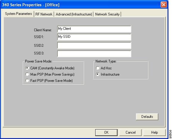
Table 5-2 lists and describes the client adapter's system parameters. Follow the instructions in the table to change any parameters.
Go to the next section to set additional parameters or click OK to return to the Profile Manager screen. On the Profile Manager screen, click OK or Apply to save your changes.
Setting RF Network Parameters
The RF Network screen (see Figure 5-2) enables you to set parameters that control how and when the client adapter transmits and receives data. To access this screen, select the RF Network tab from the Properties screens.
Figure 5-2 RF Network Screen
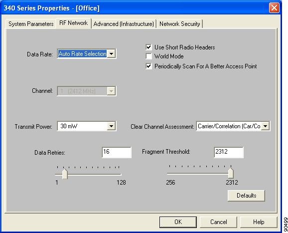
Table 5-3 lists and describes the client adapter's RF network parameters. Follow the instructions in the table to change any parameters.
|
|
|
||
|---|---|---|---|
Data Rate |
Specifies the rate at which your client adapter should transmit or receive packets to or from access points (in infrastructure mode) or other clients (in ad hoc mode). Auto Rate Selection is recommended for infrastructure mode; setting a specific data rate is recommended for ad hoc mode. Auto Rate Selection, 6 Mbps Only, 9 Mbps Only, 12 Mbps Only, 18 Mbps Only, 24 Mbps Only, 36 Mbps Only, 48 Mbps Only, or 54 Mbps Only (5-GHz client adapters) |
||
Data Rate |
|
||
|
|
|
||
Auto Rate Selection |
Auto Rate Selection |
Uses the 11-Mbps (for 2.4-GHz client adapters) or 54-Mbps (for 5-GHz client adapters) data rate when possible but drops to lower rates when necessary. |
|
1 Mbps Only |
6 Mbps Only |
Offers the greatest range but the lowest throughput. |
|
2 Mbps Only and 5.5 Mbps Only |
9 Mbps Only to 48 Mbps Only |
Progressively offers less range but greater throughput than the 1 Mbps Only (for 2.4-GHz client adapters) or 6 Mbps Only (for 5-GHz client adapters) option. |
|
11 Mbps Only |
54 Mbps Only |
Offers the greatest throughput but the lowest range. |
|
Note |
|||
Use Short Radio Headers |
Checking this check box sets your client adapter to use short radio headers. However, the adapter can use short radio headers only if the access point is also configured to support them and is using them. If any clients associated to an access point are using long headers, then all clients in that cell must also use long headers, even if both this client and the access point have short radio headers enabled. Short radio headers improve throughput performance; long radio headers ensure compatibility with clients and access points that do not support short radio headers. Note Note |
||
World Mode |
Checking this check box enables the client adapter to adopt the maximum transmit power level and the frequency range of the access point to which it is associated, provided the access point is also configured for world mode. This parameter is available only in infrastructure mode and is designed for users who travel between countries and want their client adapters to associate to access points in different regulatory domains. Note Note |
||
Periodically Scan For A Better Access Point |
Checking this check box causes the client to look for a better access point if its signal strength becomes low and to switch associations if it finds one. |
||
Channel |
Specifies which frequency your client adapter will use as the channel for communications. These channels conform to the IEEE 802.11 Standard for your regulatory domain. • • Example for 2.4-GHz client adapters: 1 to 11 (2412 to 2462 MHz) in North America Example for 5-GHz client adapters: 36, 40, 44, 48, 52, 56, 60, and 64 (5180, 5200, 5220, 5240, 5260, 5280, 5300, and 5320 MHz) in North America Example for 2.4-GHz client adapters: 6 (2437 MHz) in North America Example for 5-GHz client adapters: 36 (5180 MHz) in North America Note |
||
Transmit Power |
Defines the power level at which your client adapter transmits. This value must not be higher than that allowed by your country's regulatory agency (FCC in the U.S., DOC in Canada, ETSI in Europe, MKK in Japan, etc.). |
||
Possible Power Levels |
Client Adapter Type |
||
30 mW or 1 mW |
340 series PC cards |
||
30 mW, 15 mW, 5 mW, or |
340 series LM cards and PCI cards |
||
100 mW, 50 mW, 30 mW, 20 mW, 5 mW, or 1 mW |
350 series client adapters |
||
20 mW, 10 mW, or 5 mW |
PC-Cardbus card |
||
Note Note Note |
|||
Clear Channel Assessment |
Specifies the method that determines whether the channel on which your client adapter will operate is clear prior to the transmission of data. |
||
Method |
Description |
||
Firmware Default (XXX) |
The Clear Channel Assessment (CCA) mechanism will report that the channel is busy based on the default value of the client adapter's firmware. The firmware's CCA default value is shown in parentheses. Note |
||
Carrier/Correlation (Car/Cor) |
The CCA mechanism will report that the channel is busy upon detection of a direct-sequence spread spectrum (DSSS) signal. This signal may be above or below the ED threshold. |
||
Energy Detect (ED) |
The CCA mechanism will report that the channel is busy upon detection of any energy above the ED threshold. |
||
ED or Car/Cor |
The CCA mechanism will report that the channel is busy upon detection of a DSSS signal or any energy above the ED threshold. |
||
Note |
|||
Data Retries |
Defines the number of times a packet is resent if the initial transmission is unsuccessful. Note |
||
Fragment Threshold |
Defines the threshold above which an RF data packet is split up or fragmented. If one of those fragmented packets experiences interference during transmission, only that specific packet would need to be resent. Throughput is generally lower for fragmented packets because the fixed packet overhead consumes a higher portion of the RF bandwidth. |
||
Go to the next section to set additional parameters or click OK to return to the Profile Manager screen. On the Profile Manager screen, click OK or Apply to save your changes.
Setting Advanced Infrastructure Parameters
Note ![]() You can set advanced infrastructure parameters only if your client adapter has been set to operate in an infrastructure network. See the Network Type parameter in Table 5-2.
You can set advanced infrastructure parameters only if your client adapter has been set to operate in an infrastructure network. See the Network Type parameter in Table 5-2.
The Advanced (Infrastructure) screen (see Figure 5-3) enables you to set parameters that control how the client adapter operates within an infrastructure network. To access this screen, select the Advanced (Infrastructure) tab from the Properties screens.
Figure 5-3 Advanced (Infrastructure) Screen
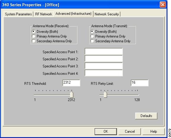
Table 5-4 lists and describes the client adapter's advanced infrastructure parameters. Follow the instructions in the table to change any parameters.
Go to the next section to set additional parameters or click OK to return to the Profile Manager screen. On the Profile Manager screen, click OK or Apply to save your changes.
Setting Advanced Ad Hoc Parameters
Note ![]() You can set advanced ad hoc parameters only if your client adapter has been set to operate in an ad hoc network. See the Network Type parameter in Table 5-2.
You can set advanced ad hoc parameters only if your client adapter has been set to operate in an ad hoc network. See the Network Type parameter in Table 5-2.
The Advanced (Ad Hoc) screen (see Figure 5-4) enables you to set parameters that control how the client adapter operates within an ad hoc network. To access this screen, select the Advanced (Ad Hoc) tab from the Properties screens.
Figure 5-4 Advanced (Ad Hoc) Screen
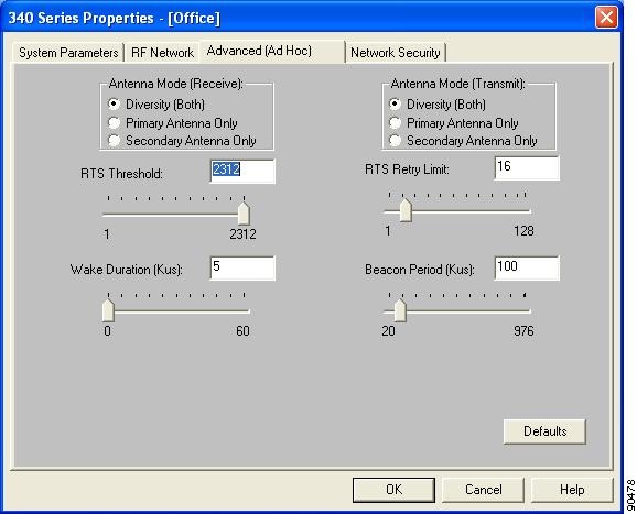
Table 5-5 lists and describes the client adapter's advanced ad hoc parameters. Follow the instructions in the table to change any parameters.
|
|
|
|---|---|
Antenna Mode (Receive) |
Specifies the antenna that your client adapter uses to receive data. • Options: Diversity (Both), Primary Antenna Only, Secondary Antenna Only Default: Diversity (Both) • Options: Diversity (Both), Primary Antenna Only, Secondary Antenna Only Default: Diversity (Both) • Default: Primary Antenna Only • Options: Diversity (Both), Primary Antenna Only, Secondary Antenna Only Default: Diversity (Both) Note Note |
Antenna Mode (Transmit) |
Specifies the antenna that your client adapter uses to transmit data. See the Antenna Mode (Receive) parameter above for information on the options available for your client adapter. Note |
RTS Threshold |
Specifies the size of the data packet that the low-level RF protocol issues to a request-to-send (RTS) packet. Setting this parameter to a small value causes RTS packets to be sent more often. When this occurs, more of the available bandwidth is consumed and the throughput of other network packets is reduced, but the system is able to recover faster from interference or collisions, which may be caused from a high multipath environment characterized by obstructions or metallic surfaces. Note |
RTS Retry Limit |
Specifies the number of times the client adapter resends a request-to-send (RTS) packet if it does not receive a clear-to-send (CTS) packet from the previously sent RTS packet. Setting this parameter to a large value decreases the available bandwidth whenever interference is encountered but makes the system more immune to interference and collisions, which may be caused from a high multipath environment characterized by obstructions or metallic surfaces. Note |
Wake Duration (Kms) |
Specifies the amount of time following a beacon that the client adapter stays awake to receive announcement traffic indication message (ATIM) packets, which are sent to the adapter to keep it awake until the next beacon. Refer to the Power Save Mode parameter in Table 5-2. Note Note |
Beacon Period (Kms) |
Specifies the duration between beacon packets, which are used to help clients find each other in ad hoc mode. |
Go to the next section to set additional parameters or click OK to return to the Profile Manager screen. On the Profile Manager screen, click OK or Apply to save your changes.
Setting Network Security Parameters
The Network Security screen (see Figure 5-5) enables you to set parameters that control how the client adapter associates to an access point, authenticates to the wireless network, and encrypts and decrypts data. To access this screen, select the Network Security tab from the Properties screens.
Figure 5-5 Network Security Screen
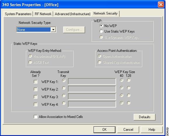
This screen is different from the other Properties screens in that it presents several security features, each of which involves a number of steps. In addition, the security features themselves are complex and need to be understood before they are implemented. Therefore, this section provides an overview of the security features as well as procedures for using them.
However, before you determine the appropriate security settings for your client adapter, you must decide how to set the Allow Association to Mixed Cells parameter, which appears at the bottom of the Network Security screen and is not associated to any of the security features. See the "Setting the Allow Association to Mixed Cells Parameter" section below.
Setting the Allow Association to Mixed Cells Parameter
The Allow Association to Mixed Cells parameter indicates whether the client adapter can associate to an access point that allows both WEP and non-WEP associations. Follow the steps below to set this parameter.
Step 1 ![]() Perform one of the following:
Perform one of the following:
•![]() Check the Allow Association to Mixed Cells check box if the access point with which the client adapter is to associate has WEP set to Optional and WEP is enabled on the client adapter. Otherwise, the client is unable to establish a connection with the access point.
Check the Allow Association to Mixed Cells check box if the access point with which the client adapter is to associate has WEP set to Optional and WEP is enabled on the client adapter. Otherwise, the client is unable to establish a connection with the access point.
•![]() Uncheck the Allow Association to Mixed Cells check box if the access point with which the client adapter is to associate does not have WEP set to Optional. This is the default setting.
Uncheck the Allow Association to Mixed Cells check box if the access point with which the client adapter is to associate does not have WEP set to Optional. This is the default setting.
Note ![]() For security reasons, Cisco recommends that WEP-enabled and WEP-disabled clients not be allowed in the same cell because broadcast packets are sent unencrypted, even to clients running WEP.
For security reasons, Cisco recommends that WEP-enabled and WEP-disabled clients not be allowed in the same cell because broadcast packets are sent unencrypted, even to clients running WEP.
Step 2 ![]() Perform one of the following:
Perform one of the following:
•![]() If you do not want to change any other parameters on the Network Security screen, click OK to return to the Profile Manager screen; then click OK or Apply to save your changes
If you do not want to change any other parameters on the Network Security screen, click OK to return to the Profile Manager screen; then click OK or Apply to save your changes
•![]() If you want to change some of the other parameters on the Network Security screen, go to the next section.
If you want to change some of the other parameters on the Network Security screen, go to the next section.
Overview of Security Features
You can protect your data as it is transmitted through your wireless network by encrypting it through the use of wired equivalent privacy (WEP) encryption keys. With WEP encryption, the transmitting device encrypts each packet with a WEP key, and the receiving device uses that same key to decrypt each packet.
The WEP keys used to encrypt and decrypt transmitted data can be statically associated with your adapter or dynamically created as part of the EAP authentication process. The information in the "Static WEP Keys" and "EAP (with Dynamic WEP Keys)" sections below can help you to decide which type of WEP keys you want to use. Dynamic WEP keys with EAP offer a higher degree of security than static WEP keys.
WEP keys, whether static or dynamic, are either 40 or 128 bits in length. 128-bit WEP keys offer a greater level of security than 40-bit WEP keys.
Note ![]() Refer to the "Additional WEP Key Security Features" section for information on three security features that can make your WEP keys even more secure.
Refer to the "Additional WEP Key Security Features" section for information on three security features that can make your WEP keys even more secure.
Static WEP Keys
Each device (or profile) within your wireless network can be assigned up to four static WEP keys. If a device receives a packet that is not encrypted with the appropriate key (as the WEP keys of all devices that are to communicate with each other must match), the device discards the packet and never delivers it to the intended receiver.
Static WEP keys are write-only and temporary; therefore, they cannot be read back from the client adapter, and they are lost when power to the adapter is removed or the Windows device is rebooted. Although the keys are temporary, you do not need to re-enter them each time the client adapter is inserted or the Windows device is rebooted. This is because the keys are stored (in an encrypted format for security reasons) in the registry of the Windows device. When the driver loads and reads the client adapter's registry parameters, it also finds the static WEP keys, unencrypts them, and stores them in volatile memory on the adapter.
The Network Security screen enables you to view the current WEP key settings for the client adapter and then to assign new WEP keys or overwrite existing WEP keys as well as to enable or disable static WEP. Refer to the "Using Static WEP" section for instructions.
EAP (with Dynamic WEP Keys)
The new standard for wireless LAN security, as defined by the Institute of Electrical and Electronics Engineers (IEEE), is called 802.1X for 802.11, or simply 802.1X. An access point that supports 802.1X and its protocol, Extensible Authentication Protocol (EAP), acts as the interface between a wireless client and an authentication server, such as a Remote Authentication Dial-In User Service (RADIUS) server, to which the access point communicates over the wired network.
Two 802.1X authentication types can be selected in ACU for use with Windows operating systems:
•![]() EAP-Cisco Wireless (or LEAP)—This authentication type is available for Windows 98, 98 SE, NT, 2000, Me, and XP, as well as non-Windows systems. Support for LEAP is provided not in the Windows operating system but in your client adapter's firmware and the Cisco software that supports it. RADIUS servers that support LEAP include Cisco Secure ACS version 2.6 and greater, Cisco Access Registrar version 1.7 and greater, and Funk Software's Steel-Belted RADIUS version 3.0 and greater.
EAP-Cisco Wireless (or LEAP)—This authentication type is available for Windows 98, 98 SE, NT, 2000, Me, and XP, as well as non-Windows systems. Support for LEAP is provided not in the Windows operating system but in your client adapter's firmware and the Cisco software that supports it. RADIUS servers that support LEAP include Cisco Secure ACS version 2.6 and greater, Cisco Access Registrar version 1.7 and greater, and Funk Software's Steel-Belted RADIUS version 3.0 and greater.
LEAP is enabled or disabled for a specific profile through ACU, provided the LEAP security module was selected during installation. After LEAP is enabled, a variety of configuration options are available, including how and when a username and password are entered to begin the authentication process.
The username and password are used by the client adapter to perform mutual authentication with the RADIUS server through the access point. The username and password are stored in the client adapter's volatile memory; therefore, they are temporary and need to be re-entered whenever power is removed from the adapter, typically due to the client adapter being ejected or the system powering down.
Note ![]() If the LEAP security module was not selected during installation, the LEAP option is unavailable in ACU. If you want to be able to enable and disable LEAP, you must run the installation program again and select LEAP.
If the LEAP security module was not selected during installation, the LEAP option is unavailable in ACU. If you want to be able to enable and disable LEAP, you must run the installation program again and select LEAP.
•![]() Host Based EAP—Selecting this option enables you to use any 802.1X authentication type for which your operating system has support. For example, if your operating system uses the Microsoft 802.1X supplicant, it provides native support for EAP-TLS authentication and general support for PEAP and EAP-SIM authentication.
Host Based EAP—Selecting this option enables you to use any 802.1X authentication type for which your operating system has support. For example, if your operating system uses the Microsoft 802.1X supplicant, it provides native support for EAP-TLS authentication and general support for PEAP and EAP-SIM authentication.
Note ![]() To use EAP-TLS, PEAP, or EAP-SIM authentication, you must install the Microsoft 802.1X supplicant, ACU, and the PEAP or EAP-SIM security module; configure your client adapter using ACU; and enable Network-EAP on the access point.
To use EAP-TLS, PEAP, or EAP-SIM authentication, you must install the Microsoft 802.1X supplicant, ACU, and the PEAP or EAP-SIM security module; configure your client adapter using ACU; and enable Network-EAP on the access point.
–![]() EAP-TLS—EAP-TLS is enabled or disabled through the operating system and uses a dynamic session-based WEP key, which is derived from the client adapter and RADIUS server, to encrypt data. Once enabled, a few configuration parameters must be set within the operating system.
EAP-TLS—EAP-TLS is enabled or disabled through the operating system and uses a dynamic session-based WEP key, which is derived from the client adapter and RADIUS server, to encrypt data. Once enabled, a few configuration parameters must be set within the operating system.
RADIUS servers that support EAP-TLS include Cisco Secure ACS version 3.0 or greater and Cisco Access Registrar version 1.8 or greater.
Note ![]() EAP-TLS requires the use of a certificate. Refer to Microsoft's documentation for information on downloading and installing the certificate.
EAP-TLS requires the use of a certificate. Refer to Microsoft's documentation for information on downloading and installing the certificate.
–![]() Protected EAP (or PEAP)—PEAP authentication is designed to support One-Time Password (OTP), Windows NT or 2000 domain, and LDAP user databases over a wireless LAN. It is based on EAP-TLS authentication but uses a password or PIN instead of a client certificate for authentication. PEAP is enabled or disabled through the operating system and uses a dynamic session-based WEP key, which is derived from the client adapter and RADIUS server, to encrypt data. If your network uses an OTP user database, PEAP requires you to enter either a hardware token password or a software token PIN to start the EAP authentication process and gain access to the network. If your network uses a Windows NT or 2000 domain user database or an LDAP user database (such as NDS), PEAP requires you to enter your username, password, and domain name in order to start the authentication process.
Protected EAP (or PEAP)—PEAP authentication is designed to support One-Time Password (OTP), Windows NT or 2000 domain, and LDAP user databases over a wireless LAN. It is based on EAP-TLS authentication but uses a password or PIN instead of a client certificate for authentication. PEAP is enabled or disabled through the operating system and uses a dynamic session-based WEP key, which is derived from the client adapter and RADIUS server, to encrypt data. If your network uses an OTP user database, PEAP requires you to enter either a hardware token password or a software token PIN to start the EAP authentication process and gain access to the network. If your network uses a Windows NT or 2000 domain user database or an LDAP user database (such as NDS), PEAP requires you to enter your username, password, and domain name in order to start the authentication process.
RADIUS servers that support PEAP authentication include Cisco Secure ACS version 3.1 or greater.
Note ![]() Service Pack 1 for Windows XP and the Microsoft 802.1X supplicant for Windows 2000 include Microsoft's PEAP supplicant, which supports a Windows username and password only and does not interoperate with Cisco's PEAP supplicant. To use Cisco's PEAP supplicant, install the Install Wizard file after Service Pack 1 for Windows XP or the Microsoft 802.1X supplicant for Windows 2000. Otherwise, Cisco's PEAP supplicant is overwritten by Microsoft's PEAP supplicant.
Service Pack 1 for Windows XP and the Microsoft 802.1X supplicant for Windows 2000 include Microsoft's PEAP supplicant, which supports a Windows username and password only and does not interoperate with Cisco's PEAP supplicant. To use Cisco's PEAP supplicant, install the Install Wizard file after Service Pack 1 for Windows XP or the Microsoft 802.1X supplicant for Windows 2000. Otherwise, Cisco's PEAP supplicant is overwritten by Microsoft's PEAP supplicant.
–![]() EAP-SIM—EAP-SIM authentication is designed for use in public wireless LANs with clients containing Gemplus SIM+ smartcards in PCSC-compliant smartcard readers. EAP-SIM is enabled or disabled through the operating system and uses a dynamic session-based WEP key, which is derived from the client adapter and RADIUS server, to encrypt data. EAP-SIM requires you to enter a user verification code, or PIN, for communication with the SIM card. You can choose to have the PIN stored in your computer or to be prompted to enter it after a reboot or prior to every authentication attempt.
EAP-SIM—EAP-SIM authentication is designed for use in public wireless LANs with clients containing Gemplus SIM+ smartcards in PCSC-compliant smartcard readers. EAP-SIM is enabled or disabled through the operating system and uses a dynamic session-based WEP key, which is derived from the client adapter and RADIUS server, to encrypt data. EAP-SIM requires you to enter a user verification code, or PIN, for communication with the SIM card. You can choose to have the PIN stored in your computer or to be prompted to enter it after a reboot or prior to every authentication attempt.
RADIUS servers that support EAP-SIM include Cisco Access Registrar version 3.0 or greater.
Note ![]() Because EAP-TLS, PEAP, and EAP-SIM authentication are enabled in the operating system and not in ACU, you cannot switch between these authentication types simply by switching profiles in ACU. You can create a profile in ACU that uses host-based EAP, but you must enable the specific authentication type in Windows (provided Windows uses the Microsoft 802.1X supplicant). In addition, Windows can be set for only one authentication type at a time; therefore, if you have more than one profile in ACU that uses host-based EAP and you want to use another authentication type, you must change authentication types in Windows after switching profiles in ACU.
Because EAP-TLS, PEAP, and EAP-SIM authentication are enabled in the operating system and not in ACU, you cannot switch between these authentication types simply by switching profiles in ACU. You can create a profile in ACU that uses host-based EAP, but you must enable the specific authentication type in Windows (provided Windows uses the Microsoft 802.1X supplicant). In addition, Windows can be set for only one authentication type at a time; therefore, if you have more than one profile in ACU that uses host-based EAP and you want to use another authentication type, you must change authentication types in Windows after switching profiles in ACU.
When you enable Network-EAP or Require EAP on your access point and configure your client adapter for LEAP, EAP-TLS, PEAP, or EAP-SIM, authentication to the network occurs in the following sequence:
1. ![]() The client associates to an access point and begins the authentication process.
The client associates to an access point and begins the authentication process.
Note ![]() The client does not gain full access to the network until authentication between the client and the RADIUS server is successful.
The client does not gain full access to the network until authentication between the client and the RADIUS server is successful.
2. ![]() Communicating through the access point, the client and RADIUS server complete the authentication process, with the password (LEAP and PEAP), certificate (EAP-TLS), or internal key stored on the SIM card and in the service provider's Authentication Center (EAP-SIM) being the shared secret for authentication. The password or internal key is never transmitted during the process.
Communicating through the access point, the client and RADIUS server complete the authentication process, with the password (LEAP and PEAP), certificate (EAP-TLS), or internal key stored on the SIM card and in the service provider's Authentication Center (EAP-SIM) being the shared secret for authentication. The password or internal key is never transmitted during the process.
3. ![]() If authentication is successful, the client and RADIUS server derive a dynamic, session-based WEP key that is unique to the client.
If authentication is successful, the client and RADIUS server derive a dynamic, session-based WEP key that is unique to the client.
4. ![]() The RADIUS server transmits the key to the access point using a secure channel on the wired LAN.
The RADIUS server transmits the key to the access point using a secure channel on the wired LAN.
5. ![]() For the length of a session, or time period, the access point and the client use this key to encrypt or decrypt all unicast packets (and broadcast packets if the access point is set up to do so) that travel between them.
For the length of a session, or time period, the access point and the client use this key to encrypt or decrypt all unicast packets (and broadcast packets if the access point is set up to do so) that travel between them.
Refer to the "Enabling LEAP" section for instructions on enabling LEAP or to the "Enabling Host-Based EAP" section for instructions on enabling EAP-TLS, PEAP, or EAP-SIM.
Note ![]() Refer to the IEEE 802.11 Standard for more information on 802.1X authentication and to the following URL for additional information on RADIUS servers: http://www.cisco.com/univercd/cc/td/doc/product/software/ios120/12cgcr/secur_c/scprt2/scrad.htm
Refer to the IEEE 802.11 Standard for more information on 802.1X authentication and to the following URL for additional information on RADIUS servers: http://www.cisco.com/univercd/cc/td/doc/product/software/ios120/12cgcr/secur_c/scprt2/scrad.htm
Additional WEP Key Security Features
The three security features discussed in this section (MIC, TKIP, and broadcast key rotation) are designed to prevent sophisticated attacks on your wireless network's WEP keys. These features do not need to be enabled on the client adapter; they are supported automatically in the firmware and driver versions included in the Install Wizard file. However, they must be enabled on the access point.
Note ![]() Access point firmware version 11.10T or greater is required to enable these security features. Refer to the software configuration guide for your access point for instructions on enabling these security features.
Access point firmware version 11.10T or greater is required to enable these security features. Refer to the software configuration guide for your access point for instructions on enabling these security features.
Message Integrity Check (MIC)
MIC prevents bit-flip attacks on encrypted packets. During a bit-flip attack, an intruder intercepts an encrypted message, alters it slightly, and retransmits it, and the receiver accepts the retransmitted message as legitimate. The MIC adds a few bytes to each packet to make the packets tamper-proof.
The Status screen indicates if MIC is being used, and the Statistics screen provides MIC statistics.
Note ![]() If you enable MIC on the access point, your client adapter's driver must support these features; otherwise, the client cannot associate.
If you enable MIC on the access point, your client adapter's driver must support these features; otherwise, the client cannot associate.
Temporal Key Integrity Protocol (TKIP)
This feature, also referred to as WEP key hashing, defends against an attack on WEP in which the intruder uses the initialization vector (IV) in encrypted packets to calculate the WEP key. TKIP removes the predictability that an intruder relies on to determine the WEP key by exploiting IVs. It protects both unicast and broadcast WEP keys.
Note ![]() If you enable TKIP on the access point, your client adapter's firmware must support these features; otherwise, the client cannot associate.
If you enable TKIP on the access point, your client adapter's firmware must support these features; otherwise, the client cannot associate.
Broadcast Key Rotation
EAP authentication provides dynamic unicast WEP keys for client devices but uses static broadcast, or multicast, keys. When you enable broadcast WEP key rotation, the access point provides a dynamic broadcast WEP key and changes it at the interval you select. When you enable this feature, only wireless client devices using LEAP, EAP-TLS, PEAP, or EAP-SIM authentication can associate to the access point. Client devices using static WEP (with open or shared key authentication) cannot associate.
Synchronizing Security Features
In order to use any of the security features discussed in this section, both your client adapter and the access point to which it will associate must be set appropriately. Table 5-6 indicates the client and access point settings required for each security feature. This chapter provides specific instructions for enabling the security features on your client adapter. Refer to the software configuration guide for your access point for instructions on enabling any of these features on the access point.
Using Static WEP
This section provides instructions for entering new static WEP keys or overwriting existing static WEP keys.
Entering a New Static WEP Key
Follow the steps below to enter a new static WEP key for this profile.
Step 1 ![]() Select None from the Network Security Type drop-down box on the Network Security screen.
Select None from the Network Security Type drop-down box on the Network Security screen.
Step 2 ![]() Select Use Static WEP Keys under WEP.
Select Use Static WEP Keys under WEP.
Step 3 ![]() Select one of the following WEP key entry methods:
Select one of the following WEP key entry methods:
•![]() Hexadecimal (0-9, A-F)—Specifies that the WEP key will be entered in hexadecimal characters, which include 0-9, A-F, and a-f.
Hexadecimal (0-9, A-F)—Specifies that the WEP key will be entered in hexadecimal characters, which include 0-9, A-F, and a-f.
•![]() ASCII Text—Specifies that the WEP key will be entered in ASCII text, which includes alpha characters, numbers, and punctuation marks.
ASCII Text—Specifies that the WEP key will be entered in ASCII text, which includes alpha characters, numbers, and punctuation marks.
Note ![]() ASCII text WEP keys are not supported on the Cisco Aironet 1200 Series Access Points, so you must select the Hexadecimal (0-9, A-F) option if you are planning to use your client adapter with these access points.
ASCII text WEP keys are not supported on the Cisco Aironet 1200 Series Access Points, so you must select the Hexadecimal (0-9, A-F) option if you are planning to use your client adapter with these access points.
Step 4 ![]() Select one of the following access point authentication options, which defines how your client adapter will attempt to authenticate to an access point:
Select one of the following access point authentication options, which defines how your client adapter will attempt to authenticate to an access point:
•![]() Open Authentication—Enables your client adapter, regardless of its WEP settings, to authenticate and attempt to communicate with an access point. Open Authentication is the default setting.
Open Authentication—Enables your client adapter, regardless of its WEP settings, to authenticate and attempt to communicate with an access point. Open Authentication is the default setting.
•![]() Shared Key Authentication—Enables your client adapter to communicate only with access points that have the same WEP key. This option is available only if Use Static WEP Keys is selected.
Shared Key Authentication—Enables your client adapter to communicate only with access points that have the same WEP key. This option is available only if Use Static WEP Keys is selected.
In shared key authentication, the access point sends a known unencrypted "challenge packet" to the client adapter, which encrypts the packet and sends it back to the access point. The access point attempts to decrypt the encrypted packet and sends an authentication response packet indicating the success or failure of the decryption back to the client adapter. If the packet is successfully encrypted/decrypted, the user is considered to be authenticated.
Note ![]() Cisco recommends that shared key authentication not be used because it presents a security risk.
Cisco recommends that shared key authentication not be used because it presents a security risk.
Step 5 ![]() For the static WEP key that you are entering (1, 2, 3, or 4), select a WEP key size of 40 or 128 on the right side of the screen. 128-bit client adapters can use 40- or 128-bit keys, but 40-bit adapters can use only 40-bit keys. If 128 bit is not supported by the client adapter, this option is unavailable.
For the static WEP key that you are entering (1, 2, 3, or 4), select a WEP key size of 40 or 128 on the right side of the screen. 128-bit client adapters can use 40- or 128-bit keys, but 40-bit adapters can use only 40-bit keys. If 128 bit is not supported by the client adapter, this option is unavailable.
Step 6 ![]() Obtain the static WEP key from your system administrator and enter it in the blank field for the key you are creating. Follow the guidelines below to enter a new static WEP key:
Obtain the static WEP key from your system administrator and enter it in the blank field for the key you are creating. Follow the guidelines below to enter a new static WEP key:
•![]() WEP keys must contain the following number of characters:
WEP keys must contain the following number of characters:
–![]() 10 hexadecimal characters or 5 ASCII text characters for 40-bit keys
10 hexadecimal characters or 5 ASCII text characters for 40-bit keys
Example: 5A5A313859 (hexadecimal) or ZZ18Y (ASCII)
–![]() 26 hexadecimal characters or 13 ASCII text characters for 128-bit keys
26 hexadecimal characters or 13 ASCII text characters for 128-bit keys
Example: 5A583135333554595549333534 (hexadecimal) or ZX1535TYUI354 (ASCII)
Note ![]() You must enter hexadecimal characters for 5-GHz client adapters if these adapters will be used with Cisco Aironet 1200 Series Access Points.
You must enter hexadecimal characters for 5-GHz client adapters if these adapters will be used with Cisco Aironet 1200 Series Access Points.
•![]() Your client adapter's WEP key must match the WEP key used by the access point (in infrastructure mode) or clients (in ad hoc mode) with which you are planning to communicate.
Your client adapter's WEP key must match the WEP key used by the access point (in infrastructure mode) or clients (in ad hoc mode) with which you are planning to communicate.
•![]() When setting more than one WEP key, the keys must be assigned to the same WEP key numbers for all devices. For example, WEP key 2 must be WEP key number 2 on all devices. When multiple WEP keys are set, they must be in the same order on all devices.
When setting more than one WEP key, the keys must be assigned to the same WEP key numbers for all devices. For example, WEP key 2 must be WEP key number 2 on all devices. When multiple WEP keys are set, they must be in the same order on all devices.
Note ![]() After you enter a WEP key, you can write over it, but you cannot edit or delete it.
After you enter a WEP key, you can write over it, but you cannot edit or delete it.
Step 7 ![]() Click the Transmit Key button to the left of the key you want to use to transmit packets. Only one WEP key can be selected as the transmit key.
Click the Transmit Key button to the left of the key you want to use to transmit packets. Only one WEP key can be selected as the transmit key.
Step 8 ![]() Click OK to return to the Profile Manager screen; then click OK or Apply to save your changes.
Click OK to return to the Profile Manager screen; then click OK or Apply to save your changes.
Overwriting an Existing Static WEP Key
Follow the steps below to overwrite an existing static WEP key.
Note ![]() You can overwrite existing WEP keys, but you cannot edit or delete them.
You can overwrite existing WEP keys, but you cannot edit or delete them.
Step 1 ![]() Look at the current WEP key settings in the middle of the Network Security screen. A checkmark appears in the Already Set? box for all existing static WEP keys.
Look at the current WEP key settings in the middle of the Network Security screen. A checkmark appears in the Already Set? box for all existing static WEP keys.
Note ![]() For security reasons, the codes for existing static WEP keys do not appear on the screen.
For security reasons, the codes for existing static WEP keys do not appear on the screen.
Step 2 ![]() Decide which existing static WEP key you want to overwrite.
Decide which existing static WEP key you want to overwrite.
Step 3 ![]() Click within the blank field of that key.
Click within the blank field of that key.
Step 4 ![]() Enter a new key, following the guidelines outlined in Step 6 of the "Entering a New Static WEP Key" section.
Enter a new key, following the guidelines outlined in Step 6 of the "Entering a New Static WEP Key" section.
Step 5 ![]() Make sure the Transmit Key button to the left of your key is selected, if you want this key to be used to transmit packets.
Make sure the Transmit Key button to the left of your key is selected, if you want this key to be used to transmit packets.
Step 6 ![]() Click OK to return to the Profile Manager screen; then click OK or Apply to save your changes
Click OK to return to the Profile Manager screen; then click OK or Apply to save your changes
Disabling Static WEP
If you ever need to disable static WEP for a particular profile, select No WEP under WEP on the Network Security screen, click OK, and click OK or Apply on the Profile Manager screen.
Note ![]() Selecting LEAP from the Network Security Type drop-down box on the Network Security screen disables static WEP automatically.
Selecting LEAP from the Network Security Type drop-down box on the Network Security screen disables static WEP automatically.
Enabling LEAP
Before you can enable LEAP authentication, your network devices must meet the following requirements:
•![]() Client adapters must support WEP and use the firmware, drivers, utilities, and security modules included in the Install Wizard file.
Client adapters must support WEP and use the firmware, drivers, utilities, and security modules included in the Install Wizard file.
•![]() Access points to which your client adapter will attempt to authenticate must use the following firmware versions or greater: 11.23T (340 and 350 series access points), 12.2(4)JA (1100 series access points), or 11.54T (1200 series access points).
Access points to which your client adapter will attempt to authenticate must use the following firmware versions or greater: 11.23T (340 and 350 series access points), 12.2(4)JA (1100 series access points), or 11.54T (1200 series access points).
•![]() All necessary infrastructure devices (for example, access points, servers, etc.) must be properly configured for LEAP authentication.
All necessary infrastructure devices (for example, access points, servers, etc.) must be properly configured for LEAP authentication.
Follow the steps below to enable LEAP authentication for this profile.
Step 1 ![]() Select LEAP from the Network Security Type drop-down box on the bottom of the Network Security screen.
Select LEAP from the Network Security Type drop-down box on the bottom of the Network Security screen.
Note ![]() The LEAP option is available only if you selected the LEAP security module during installation.
The LEAP option is available only if you selected the LEAP security module during installation.
Note ![]() When you select this option, dynamic WEP is set automatically.
When you select this option, dynamic WEP is set automatically.
Step 2 ![]() Click Configure to the right of the Network Security Type drop-down box. The LEAP Settings screen appears (see Figure 5-6).
Click Configure to the right of the Network Security Type drop-down box. The LEAP Settings screen appears (see Figure 5-6).
Figure 5-6 LEAP Settings Screen
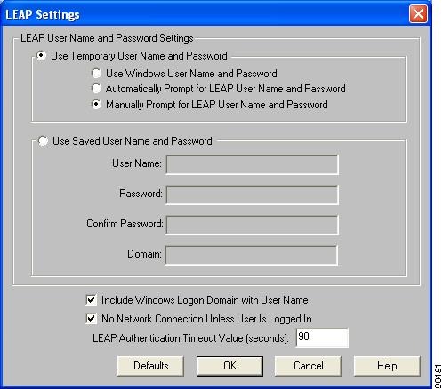
Step 3 ![]() Select one of the following LEAP username and password setting options:
Select one of the following LEAP username and password setting options:
•![]() Use Temporary User Name and Password—Requires you to enter the LEAP username and password each time the computer reboots in order to authenticate and gain access to the network.
Use Temporary User Name and Password—Requires you to enter the LEAP username and password each time the computer reboots in order to authenticate and gain access to the network.
•![]() Use Saved User Name and Password—Does not require you to enter a LEAP username and password each time the computer reboots. Authentication occurs automatically as needed using a saved username and password (which are registered with the RADIUS server).
Use Saved User Name and Password—Does not require you to enter a LEAP username and password each time the computer reboots. Authentication occurs automatically as needed using a saved username and password (which are registered with the RADIUS server).
Note ![]() The Use Saved User Name and Password option is available only if the Allow Saved LEAP User Name and Password option was enabled (set to Yes) during installation.
The Use Saved User Name and Password option is available only if the Allow Saved LEAP User Name and Password option was enabled (set to Yes) during installation.
Step 4 ![]() Perform one of the following:
Perform one of the following:
•![]() If you selected Use Temporary User Name and Password in Step 3, select one of the following options:
If you selected Use Temporary User Name and Password in Step 3, select one of the following options:
–![]() Use Windows User Name and Password—Causes your Windows username and password to also serve as your LEAP username and password, giving you only one set of credentials to remember. After you log in, the LEAP authentication process begins automatically. This option is the default setting.
Use Windows User Name and Password—Causes your Windows username and password to also serve as your LEAP username and password, giving you only one set of credentials to remember. After you log in, the LEAP authentication process begins automatically. This option is the default setting.
–![]() Automatically Prompt for LEAP User Name and Password—Requires you to enter a separate LEAP username and password (which are registered with the RADIUS server) in addition to your regular Windows login in order to start the LEAP authentication process.
Automatically Prompt for LEAP User Name and Password—Requires you to enter a separate LEAP username and password (which are registered with the RADIUS server) in addition to your regular Windows login in order to start the LEAP authentication process.
–![]() Manually Prompt for LEAP User Name and Password—Requires you to manually invoke the LEAP authentication process as needed using the Manual LEAP Login option from the Commands drop-down menu. You are not prompted to enter a LEAP username and password during the Windows login. This option might be used to support a software token one-time password system or other systems that require additional software that is not available at login.
Manually Prompt for LEAP User Name and Password—Requires you to manually invoke the LEAP authentication process as needed using the Manual LEAP Login option from the Commands drop-down menu. You are not prompted to enter a LEAP username and password during the Windows login. This option might be used to support a software token one-time password system or other systems that require additional software that is not available at login.
•![]() If you selected Use Saved User Name and Password in Step 3, follow the steps below:
If you selected Use Saved User Name and Password in Step 3, follow the steps below:
Note ![]() Usernames and passwords are limited to 32 ASCII characters each. However, if a domain name is entered in the Domain field, the sum of the username and domain name is limited to 31 ASCII characters.
Usernames and passwords are limited to 32 ASCII characters each. However, if a domain name is entered in the Domain field, the sum of the username and domain name is limited to 31 ASCII characters.
Step 5 ![]() If you work in an environment with multiple domains and, therefore, want your Windows login domain to be passed to the RADIUS server along with your username, check the Include Windows Logon Domain with User Name check box. The default setting is checked.
If you work in an environment with multiple domains and, therefore, want your Windows login domain to be passed to the RADIUS server along with your username, check the Include Windows Logon Domain with User Name check box. The default setting is checked.
Note ![]() If you selected to use a saved username and password but do not check the Include Windows Logon Domain with User Name check box, the Domain field becomes unavailable, and a domain name is not passed to the RADIUS server.
If you selected to use a saved username and password but do not check the Include Windows Logon Domain with User Name check box, the Domain field becomes unavailable, and a domain name is not passed to the RADIUS server.
Step 6 ![]() If you want to force the client adapter to disassociate after you log off so that another user cannot gain access to the wireless network using your credentials, check the No Network Connection Unless User Is Logged In check box. The default setting is checked.
If you want to force the client adapter to disassociate after you log off so that another user cannot gain access to the wireless network using your credentials, check the No Network Connection Unless User Is Logged In check box. The default setting is checked.
Step 7 ![]() In the LEAP Authentication Timeout Value field, enter the amount of time (in seconds) before a LEAP authentication is considered to be failed and an error message appears.
In the LEAP Authentication Timeout Value field, enter the amount of time (in seconds) before a LEAP authentication is considered to be failed and an error message appears.
Range: 45 to 300 seconds
Default: 90 seconds
Step 8 ![]() Click OK to exit the LEAP Settings screen.
Click OK to exit the LEAP Settings screen.
Step 9 ![]() Click OK to exit the Network Security screen and return to the Profile Manager screen. On the Profile Manager screen, click OK or Apply to save your changes.
Click OK to exit the Network Security screen and return to the Profile Manager screen. On the Profile Manager screen, click OK or Apply to save your changes.
Step 10 ![]() Refer to Chapter 6, for instructions on authenticating using LEAP.
Refer to Chapter 6, for instructions on authenticating using LEAP.
Enabling Host-Based EAP
Before you can enable host-based EAP authentication, your network devices must meet the following requirements:
•![]() Client adapters must support WEP and use the firmware, drivers, utilities, and security modules included in the Install Wizard file.
Client adapters must support WEP and use the firmware, drivers, utilities, and security modules included in the Install Wizard file.
•![]() Access points to which your client adapter may attempt to authenticate must use the following firmware versions or greater: 11.23T (340 and 350 series access points), 12.2(4)JA (1100 series access points), or 11.54T (1200 series access points).
Access points to which your client adapter may attempt to authenticate must use the following firmware versions or greater: 11.23T (340 and 350 series access points), 12.2(4)JA (1100 series access points), or 11.54T (1200 series access points).
•![]() The Microsoft 802.1X supplicant must be installed on your Windows device.
The Microsoft 802.1X supplicant must be installed on your Windows device.
•![]() All necessary infrastructure devices (for example, access points, servers, gateways, user databases, etc.) must be properly configured for the authentication type you plan to enable on the client.
All necessary infrastructure devices (for example, access points, servers, gateways, user databases, etc.) must be properly configured for the authentication type you plan to enable on the client.
Follow the steps below to enable host-based EAP authentication (EAP-TLS, PEAP, or EAP-SIM) for this profile.
Note ![]() Because EAP-TLS, PEAP, and EAP-SIM authentication are enabled in the operating system and not in ACU, you cannot switch between these authentication types simply by switching profiles in ACU. You can create a profile in ACU that uses host-based EAP, but you must enable the specific authentication type in Windows (provided Windows uses the Microsoft 802.1X supplicant). In addition, Windows can be set for only one authentication type at a time; therefore, if you have more than one profile in ACU that uses host-based EAP and you want to use another authentication type, you must change authentication types in Windows after switching profiles in ACU.
Because EAP-TLS, PEAP, and EAP-SIM authentication are enabled in the operating system and not in ACU, you cannot switch between these authentication types simply by switching profiles in ACU. You can create a profile in ACU that uses host-based EAP, but you must enable the specific authentication type in Windows (provided Windows uses the Microsoft 802.1X supplicant). In addition, Windows can be set for only one authentication type at a time; therefore, if you have more than one profile in ACU that uses host-based EAP and you want to use another authentication type, you must change authentication types in Windows after switching profiles in ACU.
Step 1 ![]() Select Host Based EAP from the Network Security Type drop-down box on the Network Security screen.
Select Host Based EAP from the Network Security Type drop-down box on the Network Security screen.
Step 2 ![]() Select Use Dynamic WEP Keys under WEP.
Select Use Dynamic WEP Keys under WEP.
Step 3 ![]() Click OK to return to the Profile Manager screen.
Click OK to return to the Profile Manager screen.
Step 4 ![]() Click OK or Apply on the Profile Manager screen to save your changes.
Click OK or Apply on the Profile Manager screen to save your changes.
Step 5 ![]() Perform one of the following, depending on your computer's operating system:
Perform one of the following, depending on your computer's operating system:
•![]() If your computer is running Windows 98, 98 SE, NT, or Me, run the Microsoft 802.1X Authentication Client application. Then go to Step 7.
If your computer is running Windows 98, 98 SE, NT, or Me, run the Microsoft 802.1X Authentication Client application. Then go to Step 7.
•![]() If your computer is running Windows 2000, double-click My Computer, Control Panel, and Network and Dial-up Connections. Right-click Local Area Connection. Click Properties. The Local Area Connection Properties screen appears.
If your computer is running Windows 2000, double-click My Computer, Control Panel, and Network and Dial-up Connections. Right-click Local Area Connection. Click Properties. The Local Area Connection Properties screen appears.
•![]() If your computer is running Windows XP, double-click My Computer, Control Panel, and Network Connections. Right-click Wireless Network Connection. Click Properties. The Wireless Network Connection Properties screen appears.
If your computer is running Windows XP, double-click My Computer, Control Panel, and Network Connections. Right-click Wireless Network Connection. Click Properties. The Wireless Network Connection Properties screen appears.
Note ![]() These instructions assume you are using Windows XP's classic view rather than its category view.
These instructions assume you are using Windows XP's classic view rather than its category view.
Step 6 ![]() Click the Authentication tab. The following screen appears (see Figure 5-7).
Click the Authentication tab. The following screen appears (see Figure 5-7).
Note ![]() When Service Pack 1 for Windows XP is released, the Authentication tab may move from its current location. To access it, click the Wireless Networks tab, select the network that you are configuring in the Preferred network list, and click Properties.
When Service Pack 1 for Windows XP is released, the Authentication tab may move from its current location. To access it, click the Wireless Networks tab, select the network that you are configuring in the Preferred network list, and click Properties.
Figure 5-7 Wireless Network Connection Properties Screen (Authentication Tab) - Windows 2000 and XP Only
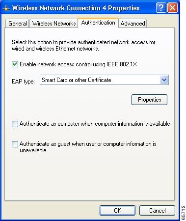
Step 7 ![]() Check the Enable network access control using IEEE 802.1X check box.
Check the Enable network access control using IEEE 802.1X check box.
Step 8 ![]() Perform one of the following, depending on the authentication type you want to use:
Perform one of the following, depending on the authentication type you want to use:
•![]() If you are planning to use EAP-TLS, go to the "Enabling EAP-TLS" section below.
If you are planning to use EAP-TLS, go to the "Enabling EAP-TLS" section below.
•![]() If you are planning to use PEAP, go to the "Enabling PEAP" section.
If you are planning to use PEAP, go to the "Enabling PEAP" section.
•![]() If you are planning to use EAP-SIM, go to the "Enabling EAP-SIM" section.
If you are planning to use EAP-SIM, go to the "Enabling EAP-SIM" section.
Enabling EAP-TLS
Follow the steps below to enable EAP-TLS.
Step 1 ![]() For EAP type, select Certificates (on Windows 98, 98 SE, NT, or Me) or Smart Card or other Certificate (on Windows 2000 or XP).
For EAP type, select Certificates (on Windows 98, 98 SE, NT, or Me) or Smart Card or other Certificate (on Windows 2000 or XP).
Step 2 ![]() Click Properties. The Certificate Properties screen (see Figure 5-8) or the Smart Card or other Certificate Properties screen appears (see Figure 5-9).
Click Properties. The Certificate Properties screen (see Figure 5-8) or the Smart Card or other Certificate Properties screen appears (see Figure 5-9).
Figure 5-8 Certificate Properties Screen - Windows 98, 98 SE, NT, and Me Only
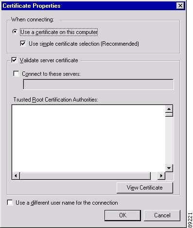
Figure 5-9 Smart Card or other Certificate Properties Screen - Windows 2000 and XP Only
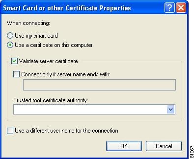
Step 3 ![]() Select the Use a certificate on this computer option.
Select the Use a certificate on this computer option.
Step 4 ![]() If your computer is running Windows 98, 98 SE, NT, or Me, make sure the Use simple certificate selection (Recommended) check box is selected.
If your computer is running Windows 98, 98 SE, NT, or Me, make sure the Use simple certificate selection (Recommended) check box is selected.
Step 5 ![]() Check the Validate server certificate check box if server certificate validation is required.
Check the Validate server certificate check box if server certificate validation is required.
Step 6 ![]() If you want to specify the name of the server to connect to, check the Connect to these servers or Connect only if server name ends with check box and enter the appropriate server name or server name suffix in the field below.
If you want to specify the name of the server to connect to, check the Connect to these servers or Connect only if server name ends with check box and enter the appropriate server name or server name suffix in the field below.
Note ![]() If you enter a server name and the client adapter connects to a server that does not match the name you entered, you are prompted to accept or cancel the connection during the authentication process.
If you enter a server name and the client adapter connects to a server that does not match the name you entered, you are prompted to accept or cancel the connection during the authentication process.
Note ![]() If you leave this field blank, the server name is not verified, and a connection is established as long as the certificate is valid.
If you leave this field blank, the server name is not verified, and a connection is established as long as the certificate is valid.
Step 7 ![]() Perform one of the following:
Perform one of the following:
•![]() If your computer is running Windows 98, 98 SE, NT, or Me, select the certificate authority from which the server certificate was downloaded in the Trusted Root Certification Authorities field.
If your computer is running Windows 98, 98 SE, NT, or Me, select the certificate authority from which the server certificate was downloaded in the Trusted Root Certification Authorities field.
•![]() If your computer is running Windows 2000 or XP, make sure that the name of the certificate authority from which the server certificate was downloaded appears in the Trusted root certificate authority field.
If your computer is running Windows 2000 or XP, make sure that the name of the certificate authority from which the server certificate was downloaded appears in the Trusted root certificate authority field.
Note ![]() If you leave this field blank, you are prompted to accept a connection to the root certification authority during the authentication process.
If you leave this field blank, you are prompted to accept a connection to the root certification authority during the authentication process.
Step 8 ![]() Click OK twice to save your settings. The configuration is complete.
Click OK twice to save your settings. The configuration is complete.
Step 9 ![]() Refer to Chapter 6, for instructions on authenticating using EAP-TLS.
Refer to Chapter 6, for instructions on authenticating using EAP-TLS.
Enabling PEAP
Follow the steps below to enable PEAP.
Step 1 ![]() For EAP type, select PEAP.
For EAP type, select PEAP.
Step 2 ![]() Click Properties. The PEAP Properties screen appears (see Figure 5-10).
Click Properties. The PEAP Properties screen appears (see Figure 5-10).
Figure 5-10 PEAP Properties Screen
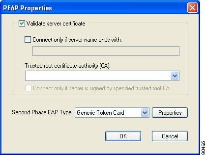
Step 3 ![]() Check the Validate server certificate check box if server certificate validation is required (recommended).
Check the Validate server certificate check box if server certificate validation is required (recommended).
Step 4 ![]() If you want to specify the name of the server to connect to, check the Connect only if server name ends with check box and enter the appropriate server name suffix in the field below.
If you want to specify the name of the server to connect to, check the Connect only if server name ends with check box and enter the appropriate server name suffix in the field below.
Note ![]() If you enter a server name and the client adapter connects to a server that does not match the name you entered, you are prompted to accept or cancel the connection during the authentication process.
If you enter a server name and the client adapter connects to a server that does not match the name you entered, you are prompted to accept or cancel the connection during the authentication process.
Note ![]() If you leave this field blank, the server name is not verified, and a connection is established as long as the certificate is valid.
If you leave this field blank, the server name is not verified, and a connection is established as long as the certificate is valid.
Step 5 ![]() Make sure that the name of the certificate authority from which the server certificate was downloaded appears in the Trusted root certificate authority (CA) field. If necessary, click the arrow on the drop-down menu and select the appropriate name.
Make sure that the name of the certificate authority from which the server certificate was downloaded appears in the Trusted root certificate authority (CA) field. If necessary, click the arrow on the drop-down menu and select the appropriate name.
Note ![]() If you leave this field blank, you are prompted to accept a connection to the root certification authority during the authentication process.
If you leave this field blank, you are prompted to accept a connection to the root certification authority during the authentication process.
Step 6 ![]() Check the Connect only if server is signed by specified trusted root CA check box if you want to ensure that the certificate server uses the trusted root certificate specified in the field above. This prevents the client from establishing connections to rogue access points.
Check the Connect only if server is signed by specified trusted root CA check box if you want to ensure that the certificate server uses the trusted root certificate specified in the field above. This prevents the client from establishing connections to rogue access points.
Step 7 ![]() Currently Generic Token Card is the only second phase EAP type available. Click Properties. The Generic Token Card Properties screen appears (see Figure 5-11).
Currently Generic Token Card is the only second phase EAP type available. Click Properties. The Generic Token Card Properties screen appears (see Figure 5-11).
Figure 5-11 Generic Token Card Properties Screen

Step 8 ![]() Select either the Static Password (Windows NT/2000, LDAP) or the One Time Password option, depending on your user database.
Select either the Static Password (Windows NT/2000, LDAP) or the One Time Password option, depending on your user database.
Step 9 ![]() Perform one of the following:
Perform one of the following:
•![]() If you selected the Static Password (Windows NT/2000, LDAP) option in Step 8, go to Step 10.
If you selected the Static Password (Windows NT/2000, LDAP) option in Step 8, go to Step 10.
•![]() If you selected the One Time Password option in Step 8, check one or both of the following check boxes to specify the type of tokens that will be supported for one-time passwords:
If you selected the One Time Password option in Step 8, check one or both of the following check boxes to specify the type of tokens that will be supported for one-time passwords:
–![]() Support Hardware Token—A hardware token device obtains the one-time password. You must use your hardware token device to obtain the one-time password and enter the password when prompted for your user credentials.
Support Hardware Token—A hardware token device obtains the one-time password. You must use your hardware token device to obtain the one-time password and enter the password when prompted for your user credentials.
–![]() Support Software Token—The PEAP supplicant works with a software token program to retrieve the one-time password. You have to enter only the PIN, not the one-time password. If you check this check box, you must also select from the Supported Type drop-down box the software token software that is installed on the client (such as Secure Computing SofToken Version 1.3, Secure Computing SofToken II 2.0, or RSA SecurID Software Token v 2.5), and if Secure Computing SofToken Version 1.3 is selected, you must locate the software program path using the Browse button.
Support Software Token—The PEAP supplicant works with a software token program to retrieve the one-time password. You have to enter only the PIN, not the one-time password. If you check this check box, you must also select from the Supported Type drop-down box the software token software that is installed on the client (such as Secure Computing SofToken Version 1.3, Secure Computing SofToken II 2.0, or RSA SecurID Software Token v 2.5), and if Secure Computing SofToken Version 1.3 is selected, you must locate the software program path using the Browse button.
Note ![]() The SofToken Program Path field is unavailable if a software token program other than Secure Computing SofToken Version 1.3 is selected.
The SofToken Program Path field is unavailable if a software token program other than Secure Computing SofToken Version 1.3 is selected.
Step 10 ![]() Click OK three times to save your settings. The configuration is complete.
Click OK three times to save your settings. The configuration is complete.
Step 11 ![]() Refer to Chapter 6, for instructions on authenticating using PEAP.
Refer to Chapter 6, for instructions on authenticating using PEAP.
Enabling EAP-SIM
Follow the steps below to enable EAP-SIM.
Step 1 ![]() For EAP type, select SIM Authentication.
For EAP type, select SIM Authentication.
Step 2 ![]() Click Properties. The SIM Authentication Properties screen appears (see Figure 5-12).
Click Properties. The SIM Authentication Properties screen appears (see Figure 5-12).
Figure 5-12 SIM Authentication Properties Screen

Step 3 ![]() To access any resources (data or commands) on the SIM, the EAP-SIM supplicant must provide a valid PIN to the SIM card, which must match the PIN stored on the SIM. Select one of the following options to specify how the EAP-SIM supplicant should handle the SIM card's PIN:
To access any resources (data or commands) on the SIM, the EAP-SIM supplicant must provide a valid PIN to the SIM card, which must match the PIN stored on the SIM. Select one of the following options to specify how the EAP-SIM supplicant should handle the SIM card's PIN:
•![]() Ask for my PIN once after I turn my computer on (recommended)—The software does not permanently store the PIN. It prompts you for the PIN once, on the first authentication of every session, where a session is defined as the time between power-up and shutdown or reboot.
Ask for my PIN once after I turn my computer on (recommended)—The software does not permanently store the PIN. It prompts you for the PIN once, on the first authentication of every session, where a session is defined as the time between power-up and shutdown or reboot.
•![]() Ask for my PIN every time the network asks for authentication—The software never stores the PIN; it prompts you for the PIN every time an EAP-SIM authentication is performed. This option is not recommended if your client will be roaming between access points or if session timeouts are implemented (such as for accounting and security purposes).
Ask for my PIN every time the network asks for authentication—The software never stores the PIN; it prompts you for the PIN every time an EAP-SIM authentication is performed. This option is not recommended if your client will be roaming between access points or if session timeouts are implemented (such as for accounting and security purposes).
•![]() Let me give my PIN to the computer now and never ask me again; PIN will be encrypted and stored on computer (not recommended)—You need to enter the PIN only once, in the Enter PIN edit box below this option. The software stores the PIN in the registry and retrieves it from there when required. If you select this option, you must enter the PIN now. The PIN is validated when an authentication attempt is made.
Let me give my PIN to the computer now and never ask me again; PIN will be encrypted and stored on computer (not recommended)—You need to enter the PIN only once, in the Enter PIN edit box below this option. The software stores the PIN in the registry and retrieves it from there when required. If you select this option, you must enter the PIN now. The PIN is validated when an authentication attempt is made.
Note ![]() This option is not recommended because it enables others to use the SIM without knowing the PIN.
This option is not recommended because it enables others to use the SIM without knowing the PIN.
Step 4 ![]() Click OK twice to save your settings. The configuration is complete.
Click OK twice to save your settings. The configuration is complete.
Step 5 ![]() If you are prompted to restart your client adapter, turn off your client adapter's radio, wait a few seconds, and then turn the radio back on. Refer to the "Turning Your Client Adapter's Radio On or Off" section for instructions.
If you are prompted to restart your client adapter, turn off your client adapter's radio, wait a few seconds, and then turn the radio back on. Refer to the "Turning Your Client Adapter's Radio On or Off" section for instructions.
Step 6 ![]() Refer to Chapter 6, for instructions on authenticating using EAP-SIM.
Refer to Chapter 6, for instructions on authenticating using EAP-SIM.
Disabling LEAP or Host-Based EAP
If you ever need to disable LEAP or host-based EAP for a particular profile, follow the instructions below for your EAP authentication type.
Disabling LEAP
To disable LEAP for a particular profile, select None from the Network Security Type drop-down box on the Network Security screen in ACU, click OK, and click OK or Apply on the Profile Manager screen.
Disabling Host-Based EAP
To disable host-based EAP (EAP-TLS, PEAP, or EAP-SIM) for a particular profile, follow the steps below:
Step 1 ![]() Select None from the Network Security Type drop-down box on the Network Security screen in ACU and click OK.
Select None from the Network Security Type drop-down box on the Network Security screen in ACU and click OK.
Step 2 ![]() Click OK or Apply on the Profile Manager screen.
Click OK or Apply on the Profile Manager screen.
Step 3 ![]() Perform one of the following, depending on your computer's operating system:
Perform one of the following, depending on your computer's operating system:
•![]() If your computer is running Windows 98, 98 SE, NT, or Me, run the Microsoft 802.1X Authentication Client application. Then go to Step 5.
If your computer is running Windows 98, 98 SE, NT, or Me, run the Microsoft 802.1X Authentication Client application. Then go to Step 5.
•![]() If your computer is running Windows 2000, double-click My Computer, Control Panel, and Network and Dial-up Connections. Right-click Local Area Connection. Click Properties. The Local Area Connection Properties screen appears.
If your computer is running Windows 2000, double-click My Computer, Control Panel, and Network and Dial-up Connections. Right-click Local Area Connection. Click Properties. The Local Area Connection Properties screen appears.
•![]() If your computer is running Windows XP, double-click My Computer, Control Panel, and Network Connections. Right-click Wireless Network Connection. Click Properties. The Wireless Network Connection Properties screen appears.
If your computer is running Windows XP, double-click My Computer, Control Panel, and Network Connections. Right-click Wireless Network Connection. Click Properties. The Wireless Network Connection Properties screen appears.
Step 4 ![]() Click the Authentication tab.
Click the Authentication tab.
Note ![]() When Service Pack 1 for Windows XP is released, the Authentication tab may move from its current location. To access it, click the Wireless Networks tab, select the network that you are configuring in the Preferred network list, and click Properties.
When Service Pack 1 for Windows XP is released, the Authentication tab may move from its current location. To access it, click the Wireless Networks tab, select the network that you are configuring in the Preferred network list, and click Properties.
Step 5 ![]() Uncheck the Enable network access control using IEEE 802.1X check box.
Uncheck the Enable network access control using IEEE 802.1X check box.
Step 6 ![]() Click OK.
Click OK.
 Feedback