- Title and copyright: SS7 Port Adapter Installation and Configuration
- Preface: SS7 Port Adapter Installation and Configuration
- Overview: SS7 Port Adapter Installation and Configuration
- Preparing to Install the SS7 Port Adapter
- Removing and Installing the SS7 Port Adapter
- Configuring the SS7 Port Adapter
SS7 Port Adapter Installation and Configuration
Bias-Free Language
The documentation set for this product strives to use bias-free language. For the purposes of this documentation set, bias-free is defined as language that does not imply discrimination based on age, disability, gender, racial identity, ethnic identity, sexual orientation, socioeconomic status, and intersectionality. Exceptions may be present in the documentation due to language that is hardcoded in the user interfaces of the product software, language used based on RFP documentation, or language that is used by a referenced third-party product. Learn more about how Cisco is using Inclusive Language.
- Updated:
- June 29, 2007
Chapter: Overview: SS7 Port Adapter Installation and Configuration
Overview
This chapter describes the SS7 Port Adapter and contains the following sections:
•![]() LEDs
LEDs
•![]() Cables, Connectors, and Pinouts
Cables, Connectors, and Pinouts
•![]() Port Adapter Slot Locations on the Cisco 7507 and Cisco 7513
Port Adapter Slot Locations on the Cisco 7507 and Cisco 7513
•![]() Identifying Interface Addresses
Identifying Interface Addresses
Port Adapter Overview
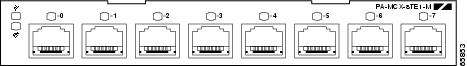
The SS7 Port Adapter is a single-width, eight-port T1/E1 port adapter with a custom hardware-assist engine to support SS7 signaling. The SS7 Port Adapter features full channelization of up to 127 HDLC-encoded SS7 (or DS0) channels at 56 Kbps or 64 Kbps. Performance monitoring, Drop and Insert, BERT functionality, external clocking (with multiple backups), internal clocking, and standard alarm integration are also supported. The hardware-assist engine provides a 30% MSU per second performance improvement on the Versatile Interface Processor (VIP) under typical conditions.
The SS7 port adapter supports MTP2, Cisco HDLC, Frame Relay, PPP, and Switched Multimegabit Data Service (SMDS) Data Exchange Interface (DXI) encapsulations over each T1 or E1 link. For SMDS only, DXI is sent on the T1 or E1 line, so it needs to connect to an SMDS switch that has direct DXI input.
Figure 1-1 shows a faceplate view of the SS7 Port Adapter.
Figure 1-1 SS7 Port Adapter—Faceplate View
Channelized T1/E1 Overview
When you are running channelized data, each DS1 interface can provide up to 24 T1 channel groups if your SS7 Port Adapter is configured for T1, or 31 E1 channel groups if your SS7 Port Adapter is configured for E1. The T1 channel groups are numbered from 0 to 23 and the E1 channel groups are numbered from 0 to 30. Each T1 channel group provides up to twenty-four 56k or 64-kbps time slots, which are numbered 1 to 24. Each E1 channel group provides up to thirty-one 64-kbps time slots, which are numbered 1 to 31. Multiple time slots can be mapped to a single channel group. Each channel group is presented to the system as a serial interface that can be configured individually. Usable bandwidth for each channel group is calculated as n x 56 kbps or n x 64 kbps, where n is the number of T1 time slots (1 to 24) or E1 channels (1 to 31).
Each of the channels on the SS7 Port Adapter uses a portion of the bandwidth (fractional T1 or E1) or the entire bandwidth for data transmission. Usable bandwidth for each channel is n x 56 kbps or n x 64 kbps, where n is a number from 1 to 24 for T1 and 1 to 31 for E1. When you are not running at full T1 and E1 speeds, the unused portion of the bandwidth cannot be used and is filled with idle channel data.

Note ![]() Time slots on the SS7 Port Adapter are numbered 1 to 24 for T1 and 1 to 31 for E1, instead of the zero-based scheme (0 to 23 or 0 to 30) used with other Cisco products. This numbering scheme is to ensure consistency with telco numbering schemes for T1 and E1 channels within channelized equipment.
Time slots on the SS7 Port Adapter are numbered 1 to 24 for T1 and 1 to 31 for E1, instead of the zero-based scheme (0 to 23 or 0 to 30) used with other Cisco products. This numbering scheme is to ensure consistency with telco numbering schemes for T1 and E1 channels within channelized equipment.
The SS7 Port Adapter supports Facility Data Link (FDL) in Extended Superframe (ESF) framing on T1 networks, as well as network and payload loopbacks. Bit error rate testing (BERT) is supported on each of the T1 or E1 links. BERT can be run only on one port at a time.
Note ![]() On a SS7 Port Adapter configured for T1, BERT is done only over a framed T1 signal.
On a SS7 Port Adapter configured for T1, BERT is done only over a framed T1 signal.
The SS7 Port AdapterSS7 Port Adapter does not support the aggregation of multiple T1s or E1s (called inverse muxing or bonding) for higher bandwidth data rates.
Features
The SS7 Port Adapter provides the following features:
•![]() Singlewide port adapter with 8 T1 or E1 RJ48c ports
Singlewide port adapter with 8 T1 or E1 RJ48c ports
•![]() Runs on Cisco 7500 Versatile Interface Processor (VIP)
Runs on Cisco 7500 Versatile Interface Processor (VIP)
•![]() Integrated CSU/DSU
Integrated CSU/DSU
•![]() Software configurable for E1/T1
Software configurable for E1/T1
•![]() Software configurable for 56/64 kbps timeslots in E1 and T1 modes
Software configurable for 56/64 kbps timeslots in E1 and T1 modes
•![]() Common external clock source with multiple backups or internal clock
Common external clock source with multiple backups or internal clock
•![]() MTP2 FISU/LSSU generation and filtering
MTP2 FISU/LSSU generation and filtering
•![]() Drop and Insert for non-SS7 timeslots
Drop and Insert for non-SS7 timeslots
•![]() ANSI, ITU, and China SS7 variant support
ANSI, ITU, and China SS7 variant support
LEDs
The SS7 Port Adapter has a green enabled LED, a bicolor alarm LED, and a bicolor port status LED for each port onthe port adapter (see Figure 1-2).
Figure 1-2 LEDs on the SS7 Port Adapter
After system initialization, the enabled LED goes on to indicate that the port adapter has been enabled for operation.
The following conditions must be met before the SS7 Port Adapter is enabled:
•![]() The SS7 Port Adapter is correctly connected and is receiving power.
The SS7 Port Adapter is correctly connected and is receiving power.
•![]() A valid system software image for the port adapter has been downloaded successfully.
A valid system software image for the port adapter has been downloaded successfully.
•![]() The system recognizes the SS7 Port Adapter.
The system recognizes the SS7 Port Adapter.
If any of the above conditions are not met, or if the initialization fails for other reasons, the enabled LED does not go on.
Table 1-1 lists the functions of the LEDs.
Cables, Connectors, and Pinouts
The T1/E1 interface receptacles on the SS7 Port Adapter are RJ-48C connectors for both T1 (100 ohm) and E1 (120 ohm).
After you properly connect a port to a line, it takes approximately 30 seconds for Cisco IOS to report that the line is up.
Each connection supports T1 (100-ohm) or E1 (120-ohm) interfaces that meet T1.403 and ACCUNET TR62411 standards. The RJ-48C connector does not require an external transceiver. The DS1 ports are T1 interfaces that use foil twisted-pair (FTP) cables.
Note ![]() Shielded cables (FTP) with 120-ohm impedance are required to comply with CE marking requirements.
Shielded cables (FTP) with 120-ohm impedance are required to comply with CE marking requirements.
Figure 1-3 shows the SS7 Port Adapter interface cable connector
Figure 1-3 SS7 Port Adapter Interface Cable Connector
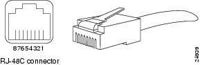
Table 1-2 lists the signal pinouts and descriptions for the RJ-48C connector.
|
|
|
|---|---|
1 |
RX tip |
2 |
RX ring |
3 |
No connection |
4 |
TX tip |
5 |
TX ring |
6 |
No connection |
7 |
No connection |
8 |
No connection |
Port Adapter Slot Locations on the Cisco 7507 and Cisco 7513
This section describes port adapter slot locations on the Cisco 7507 and Cisco 7513 platforms and summarize the slot location conventions on those platforms.
Cisco 7507 Router Slot Numbering
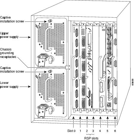
On a Cisco 7507 router, the VIP with the SS7 Port Adapter can be installed in any slot except slot 2 or 3.
Figure 1-4 shows a Cisco 7507 with an SS7 port adapter installed on the VIP in slot 5.
Figure 1-4 SS7 Port Adapter in the Cisco 7507
Cisco 7513 Router Slot Numbering
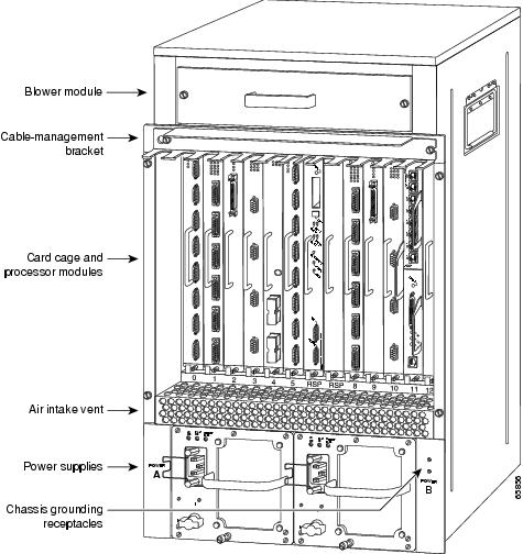
On a Cisco 7513 router, the VIP with the SS7 Port Adapter can be installed in any slot except slot 6 or 7.
Figure 1-5 shows a Cisco 7513 with an SS7 port adapter installed on the VIP in slot 11.
Figure 1-5 SS7 Port Adapter in the Cisco 7513
Identifying Interface Addresses
This section describes how to identify interface addresses for the SS7 Port Adapter in the supported platforms. Interface addresses specify the actual physical location of each interface on a router or switch.
Interfaces on a port adapter maintain the same address regardless of whether other port adapters are installed or removed. However, if you move a port adapter to a different slot, the system recognizes it as a new device. In that case the port adapter would have to be reconfigured.
Note ![]() Interface ports are numbered from left to right starting with 0.
Interface ports are numbered from left to right starting with 0.
Table 1-3 explains how to identify interface addresses for the SS7 Port Adapter on a VIP in the supported platforms.
 Feedback