Cisco 3310 Mobility Services Engine Getting Started Guide, OL-17304-01
Bias-Free Language
The documentation set for this product strives to use bias-free language. For the purposes of this documentation set, bias-free is defined as language that does not imply discrimination based on age, disability, gender, racial identity, ethnic identity, sexual orientation, socioeconomic status, and intersectionality. Exceptions may be present in the documentation due to language that is hardcoded in the user interfaces of the product software, language used based on RFP documentation, or language that is used by a referenced third-party product. Learn more about how Cisco is using Inclusive Language.
- Updated:
- March 17, 2015
Chapter: Hardware Installation
Hardware Installation
This chapter includes procedures for installing and removing the rack handles of the mobility services engine system.

Note ![]() The mobility services engine does not contain user serviceable internal components.
The mobility services engine does not contain user serviceable internal components.
This chapter contains the following sections:
•![]() Installing and Removing the Rack Handles
Installing and Removing the Rack Handles
Before You Begin
Before you begin the installation, read the Regulatory Safety and Compliance Information for the Cisco 3310 Mobility Services Engine document that shipped with your device.
This section contains the following topics:

Warning ![]() Read the installation instructions before connecting the system to the power source. Statement 1004
Read the installation instructions before connecting the system to the power source. Statement 1004
Tools and Supplies Needed
•![]() Phillips* (cross head) screwdriver, #1 bit and #2 bit
Phillips* (cross head) screwdriver, #1 bit and #2 bit
•![]() Antistatic wrist strap and conductive foam pad
Antistatic wrist strap and conductive foam pad
System References
All references to left, right, front, top, and bottom assume the reader is facing the front of the mobility services engine system as it would be positioned for normal operation.
Installing and Removing the Rack Handles
The mobility services engine is shipped with rack handles pre-installed, so that the product can be easily affixed to an equipment rack. This section includes procedures for removing and reinstalling the rack handles.
This section contains the following topics:
Removing the Rack Handles
To remove rack handles from a mobility services engine:
Step 1 ![]() Review the information in the "Safety Warnings" section on page 2-1 and the "Safety Guidelines" section on page 2-3.
Review the information in the "Safety Warnings" section on page 2-1 and the "Safety Guidelines" section on page 2-3.
Step 2 ![]() Power down the mobility services engine and unplug all peripheral devices and the AC power cable.
Power down the mobility services engine and unplug all peripheral devices and the AC power cable.
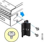
Step 3 ![]() Remove the two screws that hold the rack handle and the bezel in place, and remove the rack handle from the mobility services engine as shown in Figure 3-1.
Remove the two screws that hold the rack handle and the bezel in place, and remove the rack handle from the mobility services engine as shown in Figure 3-1.
Step 4 ![]() Reattach the bezel with the screws.
Reattach the bezel with the screws.
Figure 3-1 Removing the Rack Handle
Step 5 ![]() Repeat Step 3 and Step 4 on the opposite side of the system.
Repeat Step 3 and Step 4 on the opposite side of the system.
Step 6 ![]() Plug all peripheral devices and the AC power cable into the mobility services engine.
Plug all peripheral devices and the AC power cable into the mobility services engine.
Installing the Rack Handles
To reinstall the rack handles on a mobility services engine:
Step 1 ![]() Review the information in the "Safety Warnings" section on page 2-1 and the "Safety Guidelines" section on page 2-3.
Review the information in the "Safety Warnings" section on page 2-1 and the "Safety Guidelines" section on page 2-3.
Step 2 ![]() Power down the device and all attached devices. Disconnect the power cord and all external cables.
Power down the device and all attached devices. Disconnect the power cord and all external cables.
Step 3 ![]() Remove the two screws that attach the bezel to the chassis.
Remove the two screws that attach the bezel to the chassis.
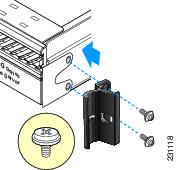
Step 4 ![]() Attach the rack handle to the mobility services engine with the two screws as shown in Figure 3-2.
Attach the rack handle to the mobility services engine with the two screws as shown in Figure 3-2.
Figure 3-2 Installing the Rack Handle
Step 5 ![]() Repeat Step 3 and Step 4 on the opposite side of the mobility services engine.
Repeat Step 3 and Step 4 on the opposite side of the mobility services engine.
Step 6 ![]() Plug all peripheral devices and the AC power cable into the mobility services engine.
Plug all peripheral devices and the AC power cable into the mobility services engine.
 Feedback