- Cisco Unified Wireless Network Solution Overview
- Cisco Unified Wireless Technology and Architecture
- WLAN RF Design Considerations
- Cisco Unified Wireless Network Architecture—Base Security Features
- Cisco Unified Wireless QoS and AVC
- Cisco Unified Wireless Multicast Design
- FlexConnect
- Cisco Wireless Mesh Networking
- VoWLAN Design Recommendations
- Cisco Unified Wireless Network Guest Access Services
- 802.11r, 802.11k, 802.11v, 802.11w Fast Transition Roaming
Enterprise Mobility 8.1 Design Guide
Bias-Free Language
The documentation set for this product strives to use bias-free language. For the purposes of this documentation set, bias-free is defined as language that does not imply discrimination based on age, disability, gender, racial identity, ethnic identity, sexual orientation, socioeconomic status, and intersectionality. Exceptions may be present in the documentation due to language that is hardcoded in the user interfaces of the product software, language used based on RFP documentation, or language that is used by a referenced third-party product. Learn more about how Cisco is using Inclusive Language.
- Updated:
- October 26, 2015
Chapter: Cisco Unified Wireless Multicast Design
Cisco Unified Wireless Multicast Design
Introduction
This chapter describes the Cisco Unified Wireless Multicast in IP multicast forwarding and provides information on how to deploy multicast in a wireless environment. A prerequisite for using the multicast performance functionality is that a multicast-enabled network must be configured on all routers between the controllers and the Access Points (APs). To accommodate networks that do not support multicast, the controller continues to support the original unicast packet forwarding mechanism.
IP multicast is a delivery protocol for information to a group of destinations. It uses the most efficient strategy to deliver the information over each link of the network. It sends only one copy of the information at each hop of the network, creating copies only when the links to the destinations split. Typically, many of today’s networks applications use unicast packets i.e., from one source to one destination. However, when multiple receivers require the same data, replicating the data from the source to all the receivers as individual unicast packets increases the network load. IP multicast enables efficient transfer of data from a set of sources to a dynamically formed set of receivers.
IP multicast is typically used today for one way streaming media, such as video to large groups of receivers. Many cable TV operators, educational institutions and large enterprises have deployed IP multicast for their content delivery needs. Additionally, there have been some uses of audio and video conferencing using multicast. Another widespread use of multicast within campus and commercial networks is for file distribution, particularly to deliver operating system images and updates to remote hosts. IP multicast has also seen deployment within the financial sector for applications such as stock tickers and hoot-n-holler systems.
Overview of IPv4 Multicast Forwarding
With Cisco Unified Wireless Network Software Releases, significant enhancements were made to support the effective use of multicast in a wireless network.
With the current Cisco Unified Wireless multicast support, each multicast frame received by the controller from a VLAN on the first hop router is copied and sent to the multicast group configured on the controller for the AP that is associated, as shown in Figure 6-1. The multicast CAPWAP packet containing the multicast packet uses a WLAN bitmap, which tells the receiving AP which WLAN it must forward the packet to. When the AP receives the CAPWAP packet, it strips off the outer CAPWAP encapsulation and transmits the multicast packet to the WLAN (on all radios associated to the WLAN) identified in the CAPWAP WLAN ID bitmask.
Figure 6-1 Multicast Forwarding Mechanism
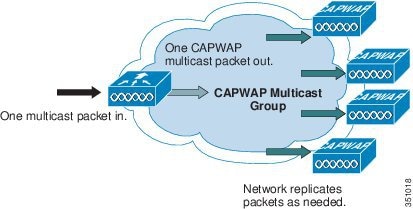
Effectively, enabling Global Multicast mode delivers the multicast packet to each access point. This allows the routers in the network to use standard multicast techniques to replicate and deliver multicast packets to the APs. For the CAPWAP multicast group, the controller becomes the multicast source and the APs become the multicast receivers.

Note![]() A prerequisite for using the multicast performance functionality is that a multicast enabled network is configured on all routers between the controllers and the APs. To accommodate networks that do not support multicast, the controller continues to support the original unicast packet forwarding mechanism.
A prerequisite for using the multicast performance functionality is that a multicast enabled network is configured on all routers between the controllers and the APs. To accommodate networks that do not support multicast, the controller continues to support the original unicast packet forwarding mechanism.
Note![]() With multicast enabled, any kind of multicast packet received on the VLAN from the first hop router is transmitted over the wireless including HSRP hellos, all router, routing protocol, and PIM multicast packets.
With multicast enabled, any kind of multicast packet received on the VLAN from the first hop router is transmitted over the wireless including HSRP hellos, all router, routing protocol, and PIM multicast packets.
After the administrator enables multicast (multicast mode is disabled by default), configures a CAPWAP multicast group, and enables IGMP snooping, the access point downloads the controller’s CAPWAP multicast group address during the normal join process (at boot time) to the controller. After an access point joins a controller and downloads its configuration, the AP issues an Internet Group Management Protocol (IGMP) join request to join the controller’s CAPWAP multicast group. This triggers the normal setup for the multicast state in the multicast-enabled routers between the controller and APs. The source IP address for the multicast group is the controller’s management interface IP address, not the AP-manager IP address used for Layer 3 mode. Once the AP has joined the controllers CAPWAP multicast group, the multicast algorithm for client multicast traffic works as described below.
When the source of the multicast group is on the wired LAN:
- When the controller receives a multicast packet from any of the client VLANs on the first hop router, it transmits the packet to the CAPWAP multicast group via the management interface at the best effort QoS classification. The QoS bits for the CAPWAP multicast packet are hard coded at the lowest level and are not user changeable.
- The multicast-enabled network delivers the CAPWAP multicast packet to each of the access points that have joined the CAPWAP multicast group, using the normal multicast mechanisms in the routers to replicate the packet along the way as needed so that the multicast packet reaches all APs (Figure 6-1). This relieves the controller from replicating the multicast packets.
- Access points may receive other multicast packets but will only process the multicast packets that are sourced from the controller they are currently joined to; any other copies are discarded. If more than one WLAN is associated to the VLAN interface where the original multicast packet was sourced, the AP transmits the multicast packet over each WLAN (following the WLAN bitmap in the CAPWAP header). Additionally, if that WLAN is on both radios (802.11g and 802.11a), both radios transmit the multicast packet on the WLAN if there are clients associated, even if those clients did not request the multicast traffic.
When the source of the multicast group is a wireless client:
- The multicast packet is unicast (CAPWAP encapsulated) from the AP to the controller similar to standard wireless client traffic.
- The controller makes two copies of the multicast packet. One copy is sent out the VLAN associated with the WLAN it came on, enabling receivers on the wired LAN to receive the multicast stream and the router to learn about the new multicast group. The second copy of the packet is CAPWAP-encapsulated and is sent to the CAPWAP multicast group so that wireless clients may receive the multicast stream.
Wireless Multicast Roaming
A major challenge for a multicast client in a wireless environment is maintaining its multicast group membership when moving about the WLAN. Drops in the wireless connection moving from AP-to-AP can cause a disruption in a client’s multicast application. Internet Group Management Protocol (IGMP) plays an important role in the maintenance of dynamic group membership information.
A basic comprehension of IGMP is important for understanding what happens to a client’s multicast session when it roams about the network. In a Layer 2 roaming case, sessions are maintained simply because the foreign AP, if configured properly, already belongs to the multicast group and traffic is not tunneled to a different anchor point on the network. Layer 3 roaming environments are a little more complex in this manner and depending on what tunneling mode you have configured on your controllers, the IGMP messages sent from a wireless client will be affected. The default mobility tunneling mode on a controller is asymmetrical. As discussed in the “Cisco Unified Wireless Technology and Architecture,” this means that return traffic to the client is sent to the anchor WLC then forwarded to the foreign WLC where the associated client connection resides. Outbound packets are forwarded out the foreign WLC interface. In symmetrical mobility tunneling mode, both inbound and outbound traffic are tunneled to the anchor controller. For more information on mobility tunneling, see Chapter2, “Cisco Unified Wireless Technology and Architecture”
Asymmetric Multicast Tunneling
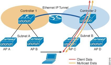
In asymmetric multicast tunneling, when a client roams to a new AP associated to a different WLC and on a different subnet, it is queried for its multicast group memberships by the foreign WLC and send out an IGMP group membership report. This is forwarded out the foreign WLC dynamic interface assigned to the VLAN and the client rejoins the multicast stream through the foreign subnet. Figure 6-2 illustrates the traffic flow for normal data and multicast data.
Figure 6-2 Asymmetric Tunneling
Note![]() In the event of a client roam, there is a slight disruption in the multicast session; in some applications it might be considered unsuitable for use.
In the event of a client roam, there is a slight disruption in the multicast session; in some applications it might be considered unsuitable for use.
Multicast Enabled Networks
A prerequisite for using this new multicast performance functionality is that a multicast enabled network is configured on all routers between the controllers and the APs. A multicast-enabled network allows for an efficient way to deliver a packet to many hosts across the network. IP multicast is a bandwidth-conserving technology that reduces traffic by simultaneously delivering a single stream of information to thousands of corporate recipients. Packets are replicated as necessary at each Layer 3 point in the network. A multicast routing protocol, such as PIM, is required if there is more than one router between the controllers and APs. For more information on setting up a multicast-enabled network, refer to the following URL: http://www.cisco.com/go/multicast.
CAPWAP Multicast Reserved Ports and Addresses
The controller blocks all multicast packets sent to any multicast group that have a destination port of 5246, 5247, and 5248. Additionally, all packets with a multicast group address equal to the controller’s CAPWAP multicast group address are blocked at the controller. This is to prevent fragmented CAPWAP encapsulated packets from another controller being retransmitted (see the Fragmentation and CAPWAP Multicast Packets section for more information). Ensure that the multicast applications on your network do not use these reserved ports or CAPWAP multicast group addresses.
Enabling IPv4 Multicast Forwarding on the Controller
IP Multicast traffic through the controller is disabled by default. WLAN clients cannot receive multicast traffic when it is disabled. If you wish to turn on multicast traffic to the WLAN clients, follow these steps:
Enabling IPv4 Multicast Mode (GUI)
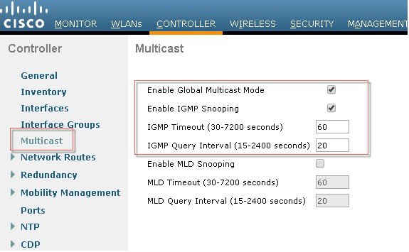
Step 1![]() Choose Controller > Multicast to open the Multicast page.
Choose Controller > Multicast to open the Multicast page.
Step 2![]() Check the Enable Global Multicast Mode check box to configure sending multicast packets. The default value is disabled.
Check the Enable Global Multicast Mode check box to configure sending multicast packets. The default value is disabled.
Note![]() FlexConnect supports unicast mode only.
FlexConnect supports unicast mode only.
Step 3![]() If you want to enable IGMP snooping, check the Enable IGMP Snooping check box. If you want to disable IGMP snooping, leave the check box unchecked. The default value is disabled.
If you want to enable IGMP snooping, check the Enable IGMP Snooping check box. If you want to disable IGMP snooping, leave the check box unchecked. The default value is disabled.
Step 4![]() To set the IGMP timeout, enter a value between 30 and 7200 seconds in the IGMP Timeout text box. The controller sends three queries in one timeout value at an interval of timeout/ 3 to see if any clients exist for a particular multicast group. If the controller does not receive a response through an IGMP report from the client, the controller times out the client entry from the MGID table. When no clients are left for a particular multicast group, the controller waits for the IGMP timeout value to expire and then deletes the MGID entry from the controller. The controller always generates a general IGMP query (that is, to destination address 224.0.0.1) and sends it on all WLANs with an MGID value of 1.
To set the IGMP timeout, enter a value between 30 and 7200 seconds in the IGMP Timeout text box. The controller sends three queries in one timeout value at an interval of timeout/ 3 to see if any clients exist for a particular multicast group. If the controller does not receive a response through an IGMP report from the client, the controller times out the client entry from the MGID table. When no clients are left for a particular multicast group, the controller waits for the IGMP timeout value to expire and then deletes the MGID entry from the controller. The controller always generates a general IGMP query (that is, to destination address 224.0.0.1) and sends it on all WLANs with an MGID value of 1.
Step 5![]() Enter the IGMP Query Interval (seconds).
Enter the IGMP Query Interval (seconds).
When IGMP snooping is disabled, the following is true:
- The controller always uses Layer 2 MGID when it sends multicast data to the access point. Every interface created is assigned with one Layer 2 MGID. For example, the management interface has an MGID of 0, and the first dynamic interface created is assigned an MGID of 8, which increments as each dynamic interface is created.
- The IGMP packets from clients are forwarded to the router. As a result, the router IGMP table is updated with the IP address of the clients as the last reporter.
When IGMP snooping is enabled, the following is true:
- The controller always uses Layer 3 MGID for all Layer 3 multicast traffic sent to the access point. For all Layer 2 multicast traffic, it continues to use Layer 2 MGID.
- IGMP report packets from wireless clients are consumed or absorbed by the controller, which generates a query for the clients. After the router sends the IGMP query, the controller sends the IGMP reports with its interface IP address as the listener IP address for the multicast group. As a result, the router IGMP table is updated with the controller IP address as the multicast listener.
- When the client that is listening to the multicast groups roams from one controller to another, the first controller transmits all the multicast group information for the listening client to the second controller. As a result, the second controller can immediately create the multicast group information for the client. The second controller sends the IGMP reports to the network for all multicast groups to which the client was listening. This process aids in the seamless transfer of multicast data to the client.
- If the listening client roams to a controller in a different subnet, the multicast packets are tunneled to the anchor controller of the client to avoid the reverse path filtering (RPF) check. The anchor then forwards the multicast packets to the infrastructure switch. The MGIDs are controller specific. The same multicast group packets coming from the same VLAN in two different controllers may be mapped to two different MGIDs.
Note![]() The number of multicast addresses supported per VLAN for a Cisco WLC is 100.
The number of multicast addresses supported per VLAN for a Cisco WLC is 100.
Step 6![]() If you have a multicast enabled network, choose Multicast from the AP Multicast Mode drop-down list to use the method where the network replicates the packets.
If you have a multicast enabled network, choose Multicast from the AP Multicast Mode drop-down list to use the method where the network replicates the packets.
Step 7![]() If you do not have a multicast enabled network, choose Unicast from the AP Multicast Mode drop-down list to use the method where the controller replicates the packets.
If you do not have a multicast enabled network, choose Unicast from the AP Multicast Mode drop-down list to use the method where the controller replicates the packets.
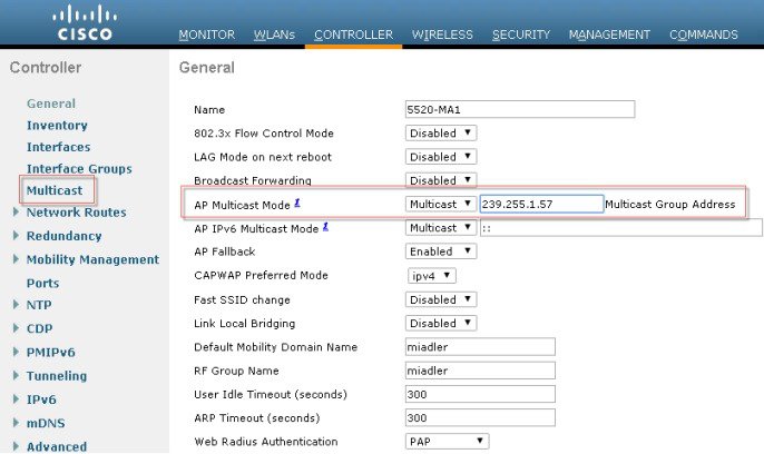
Step 8![]() Choose Multicast from the AP Multicast Mode drop-down list and enter a multicast group address. This option is shown in Figure 6-3.
Choose Multicast from the AP Multicast Mode drop-down list and enter a multicast group address. This option is shown in Figure 6-3.
Figure 6-3 Commands to turn on Ethernet Multicast Mode via the GUI.
Information About Multicast Mode
If your network supports packet multicasting, you can configure the multicast method that the controller uses.
The controller performs multicasting in two modes:
Unicast mode—In this mode, the controller unicasts every multicast packet to every access point associated to the controller. This mode is inefficient but might be required on networks that do not support multicasting.
Multicast mode—In this mode, the controller sends multicast packets to a CAPWAP multicast group. This method reduces overhead on the controller processor and shifts the work of packet replication to your network, which is much more efficient than the unicast method.
When you enable multicast mode and the controller receives a multicast packet from the wired LAN, the controller encapsulates the packet using CAPWAP and forwards the packet to the CAPWAP multicast group address. The controller always uses the management interface for sending multicast packets. Access points in the multicast group receive the packet and forward it to all the BSSIDs mapped to the interface on which clients receive multicast traffic. From the access point perspective, the multicast appears to be a broadcast to all SSIDs.
Multicast Deployment Considerations
Recommendations for Choosing a CAPWAP Multicast Address

Cisco recommends that multicast addresses be assigned from the administratively scoped block 239/8. IANA has reserved the range of 239.0.0.0-239.255.255.255 as administratively scoped addresses for use in private multicast domains (see the note below for additional restrictions). These addresses are similar in nature to the reserved private IP unicast ranges (such as 10.0.0.0/8) defined in RFC 1918. Network administrators are free to use the multicast addresses in this range inside of their domain without fear of conflicting with others elsewhere in the Internet. This administrative or private address space should be used within the enterprise and blocked from leaving or entering the autonomous domain (AS).
Note![]() Do not use the 239.0.0.X address range or the 239.128.0.X address range. Addresses in these ranges overlap with the link local MAC addresses and will flood out all switch ports even with IGMP snooping turned on.
Do not use the 239.0.0.X address range or the 239.128.0.X address range. Addresses in these ranges overlap with the link local MAC addresses and will flood out all switch ports even with IGMP snooping turned on.
Cisco recommends that enterprise network administrators further subdivide this address range into smaller geographical administrative scopes within the enterprise network to limit the “scope” of particular multicast applications. This is used to prevent high-rate multicast traffic from leaving a campus (where bandwidth is plentiful) and congesting the WAN links. It also allows for efficient filtering of the high bandwidth multicast from reaching the controller and the wireless network.
For more information on multicast address guidelines, refer to the document at the following URL:
http://www.cisco.com/en/US/tech/tk828/technologies_white_paper09186a00802d4643.shtml
Fragmentation and CAPWAP Multicast Packets
When a controller receives a multicast packet, it encapsulates the packet inside of CAPWAP using the CAPWAP multicast group as a destination address and forwards it to the APs via the management interface (source address). If the packet exceeds the MTU of the link, the controller fragments the packet and send out both packets to the CAPWAP multicast group. If another controller were to receive this CAPWAP encapsulated multicast packet via the wired network, it would re-encapsulate it again, treating it as a normal multicast packet and forward it to its APs.
There are two different options to prevent this from happening, either of which is effective by itself. One, you may assign all controllers to the same CAPWAP multicast group address. Or two, you can apply standard multicast filtering techniques to ensure that CAPWAP encapsulated multicast packets do not reach any other controller. If all controllers have the same CAPWAP multicast group or different groups, Table 6-1 lists the pros and cons of these two techniques.
All Controllers have the Same CAPWAP Multicast Group
To prevent the second controller from retransmitting these CAPWAP encapsulated packets, the controller blocks incoming multicast packets to the CAPWAP multicast group and the CAPWAP reserved ports. By blocking the reserved ports, the controller blocks the first part of a fragmented packet in an encapsulated CAPWAP multicast packet. However, the second packet does not contain port numbers and can only be blocked by filtering it on the multicast group address (destination address). The controller blocks any packets where the destination address is equal to the CAPWAP multicast group address assigned to the controller.
However, assigning every controller to the same CAPWAP multicast group creates other problems. IGMP version 1 and 2 used by the APs to join the CAPWAP multicast group use Any Source Multicast (ASM) and the APs will receive multicast traffic from all sources of the multicast group in the network. This means the APs will receive multicast packets from all of the controllers on the network if the controllers are configured with the same multicast group address, and no multicast boundaries have been applied. One controller’s multicast traffic will flood out to all of the APs across the network and every APs receive (and drop it if the source address is not equal to its controller’s management address) the multicast traffic that is being received from any wireless multicast client in the entire network. Additionally, locally sourced multicast packets from any client VLAN such as HSRP, PIM, and EIGRP and OSPF multicast packets will also be flooded throughout the network.
Controlling Multicast on the WLAN Using Standard Multicast Techniques
Normal boundary techniques should be used in your multicast enabled network. These include using the ip multicast boundary interface mode command, which filters IP multicast traffic and also Auto-RP messages.
Note![]() A wired client anywhere in the network may request the CAPWAP multicast stream and receive it from all sources (if multicast boundaries are not applied). Multicast streams are not encrypted when they are encapsulated in the CAPWAP multicast packet. Therefore, it is recommended that multicast boundaries be implemented to block this type of access.
A wired client anywhere in the network may request the CAPWAP multicast stream and receive it from all sources (if multicast boundaries are not applied). Multicast streams are not encrypted when they are encapsulated in the CAPWAP multicast packet. Therefore, it is recommended that multicast boundaries be implemented to block this type of access.
In the past, Time To Live field in the IP Multicast datagram was used for creating Auto-RP administrative boundaries using the ttl-threshold command. This has been superseded by the ip multicast boundary interface mode command, which filters IP multicast traffic and also Auto-RP messages. Cisco recommends using the new command.
Other useful commands include the ip multicast rate-limit interface command. This command enforces low rates on the wireless VLANs. Without it, even if the network engineer filters the high rate multicast addresses, a low rate multicast address cannot exceed its rate.
A typical example on a wireless client VLAN is given below. For more information on other multicast commands for a multicast enabled network refer to http://www.cisco.com/go/multicast. Filtering for multicast-enabled traffic also allows you to prevent propagation of certain worms like the sasser worm which relied on the TCP and ICMP transports with multicast addresses. Blocking these types of traffic with multicast group addresses does not affect most applications since they typically use UDP or TCP for streaming.
In the following example, packets to the multicast group range 239.0.0.0 to 239.127.255.255 from any source will have their packets rate-limited to 128 kbps. The example also sets up a boundary for all multicast addresses not in the lower administratively scoped addresses. In addition, hosts serviced by Vlan40 can only join the lower administrative groups 239.0.0.0 to 239.127.255.255.
How Controller Placement Impacts Multicast Traffic and Roaming
Note![]() The multicast stream in either deployment, distributed or collocated, is not rate-limited and there is no way to put ACLs on it. Once enabled, all multicast traffic is forwarded to the wireless LAN including HSRP, EIGRP, OSPF, and PIM packets.
The multicast stream in either deployment, distributed or collocated, is not rate-limited and there is no way to put ACLs on it. Once enabled, all multicast traffic is forwarded to the wireless LAN including HSRP, EIGRP, OSPF, and PIM packets.
We look at two different deployments (distributed and centralized) and how they impact roaming with multicast clients. In a centralized deployment, WLC WLAN interfaces are attached to the same VLANs/ subnets, the multicast streams is uninterrupted when a multicast client roams from APs on one WLC to an AP on another WLC. The centralized deployment creates a flat WLC client multicast network. The reason centralized WLCs do not affect multicast roaming is because once the multicast stream is requested from a single multicast client on a WLAN, it streams out all APs on that WLAN, on all radios (802.11g and 802.11a), on all WLCs, even if that access point WLAN has no clients associated with it that have requested the multicast traffic. If you have more than one WLAN associated to the VLAN, the AP transmits the multicast packet over each WLAN. Both the unicast mode CAPWAP packet and the multicast mode CAPWAP packet contain a WLAN bitmap that tells the receiving AP which WLAN it must forward the packet over.
The distributed deployment does not have this problem because while the WLANs are the same, the WLCs are attached to different VLANs. This means that when the multicast client roams to a new WLC, the WLC will first query the client for its multicast group memberships. At this point the client responds with its group membership report and the WLC forwards this message to the appropriate multicast group address through the VLAN associated with its local VLAN. This allows the client to resume its multicast session through the foreign WLC.
The distributed deployment reduces the amount of multicast traffic on the APs because, although the WLAN SSIDs are the same, the WLCs are attached to different VLANs. WLAN multicast traffic depends on a client request on the VLAN of that WLC. Table 6-2 lists the advantages and disadvantages of distributed and collocated deployments.
Additional Considerations
Two areas for additional consideration in multicast deployment are when implementing AP groups, and FlexConnect and APs. AP groups allow APs on the same controller to map the same WLAN (SSID) to different VLANs. If a client is roaming between APs in different groups, the multicast session will not function properly as this is currently not supported. Currently, the WLC forwards multicast only for the VLAN configured on the WLAN and does not take into consideration VLANs configured in AP groups.
FlexConnect APs allow the local termination of WLANs at the network edge rather than at the WLC, and the multicast behavior is controlled at that edge. If a FlexConnect WLAN is terminated on a WLC and multicast is enabled on that WLC, multicast is delivered to that FlexConnect WLAN, if the CAPWAP multicast group is allowed to extend to the FlexConnect network location.
Even if the CAPWAP multicast packets are not able to transit the network to the FlexConnect AP, WLAN clients on that FlexConnect AP are able to send IGMP joins to the network connected to the WLC, as these are unicast messages.
Information About 802.11v and Directed Multicast
From Release 8.1, controller supports 802.11v amendment for wireless networks, which describes numerous enhancements to wireless network management.
One such enhancement is Network assisted Power Savings which helps clients to improve battery life by enabling them to sleep longer. As an example, mobile devices typically use a certain amount of idle period to ensure that they remain connected to access points and therefore consume more power when performing the following tasks while in a wireless network.
Another enhancement is Network assisted Roaming which enables the WLAN to send requests to associated clients, advising the clients to choose better APs to associate. This is useful for both load balancing and for directing poorly connected clients.
Enabling 802.11v Network Assisted Power Savings
Wireless devices consume battery to maintain their connection to the clients, in several ways:
- By waking up at regular intervals to listen to the access point beacons containing a DTIM, which indicates buffered broadcast or multicast traffic that the access point will deliver to the clients.
- By sending null frames to the access points, in the form of keepalive messages to maintain connection with access points.
- Devices also periodically listen to beacons (even in the absence of DTIM fields) to synchronize their clock to that of the corresponding access point.
All these processes consume battery and this consumption particularly impacts devices (such as Apple), because these devices use a conservative session timeout estimation, and therefore, wake up often to send keepalive messages. The 802.11 standard, without 802.11v, does not include any mechanism for the controller or the access points to communicate to wireless clients about the session timeout for the local client.
To save the power of clients due to the mentioned tasks in wireless network, the following features in the 802.11v standard are used:
Directed Multicast Service
Using Directed Multicast Service (DMS), the client requests the access point to transmit the required multicast packet as unicast frames. This allows the client to receive the multicast packets it has ignored while in sleep mode and also ensures Layer 2 reliability. Also, the unicast frame will be transmitted to the client at a potentially higher wireless link rate, which enables the client to receive the packet quickly by enabling the radio for a shorter duration, thus saving battery power. As the wireless client does not have to wake up at each DTIM interval to receive multicast traffic, longer sleeping intervals are allowed.
BSS Max Idle Period
The BSS Max Idle period is the timeframe during which an access point (AP) does not disassociate a client due to non-receipt of frames from the connected client. This ensures that the client device does not send keepalive messages frequently. The idle period timer value is transmitted using the association and reassociation response frame from the access point to the client. The idle time value indicates the maximum time a client can remain idle without transmitting any frame to an access point. As a result, the clients remain in sleep mode for a longer duration without transmitting the keepalive messages often. This in turn contributes to saving battery power.
Configuring 802.11v Network Assisted Power Savings (CLI)
–![]() config wlan usertimeout wlan-id
config wlan usertimeout wlan-id
Overview of IPv6 Multicast
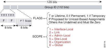
A multicast address is defined as an identifier for a set of interfaces that belong to different nodes. Multicast addresses are normally used to identify groups of interfaces that are interested in receiving similar content (for example, video). The conversation model in this case is a one-to-many model. Multicast addresses are all assigned out of the FF00::/8 block.
Multicast addresses also have a scope associated with them. The scopes are very similar to the scopes defined for unicast addresses:
- Link local—Link local multicast addresses are only intended for systems on a link and must not be forwarded by network equipment off that link. This behavior is the same as link local unicast addresses.
- Organization—Organizational multicast addresses are intended for use within an organization. These addresses are similar to the unicast unique local addresses.
- Global—Global multicast addresses are usable across the Internet similar to the unicast globally unique addresses.
There are some additionally defined scopes for IPv6 multicast addresses:
- Interface local—Interface local multicast addresses are intended for transmission of multicast within a node.
- Site local—Site local multicast addresses are intended for use within a single site.
Figure 6-4 lays out the format of an IPv6 multicast address.
Similar to the unicast address space, there are some reserved or special use multicast addresses. A couple of the more common multicast groups and their intended use are mentioned below. For a more comprehensive list of currently assigned multicast addresses, see: http://www.iana.org/assignments/ipv6-multicast-addresses
Some of the more common multicast addresses seen on IPv6 systems include:
- FF02::1—Link local, all nodes address
- FF02::2—Link local, all routers address
- FF02:0:0:0:0:1:FFXX:XXXX—Link local, solicited-node address
Figure 6-4 Multicast Address Representation
Multicast Listener Discover – MLD
Cisco software supports the following protocols to implement IPv6 multicast routing:
- MLD for IPv6. MLD is used by IPv6 routers and controllers to discover multicast listeners (nodes that want to receive multicast packets destined for specific multicast addresses) on directly attached links. There are two versions of MLD: MLD version 1 is based on version 2 of the Internet Group Management Protocol (IGMP) for IPv4, and MLD version 2 is based on version 3 of the IGMP for IPv4. IPv6 multicast for Cisco software uses both MLD version 2 and MLD version 1.
MLD version 2 is fully backward compatible with MLD version 1 (described in RFC 2710). Hosts that support only MLD version 1 will interoperate with a router running MLD version 2. Mixed LANs with both MLD version 1 and MLD version 2 hosts are likewise supported. - PIM-SM is used between routers so that they can track which multicast packets to forward to each other and to their directly connected LANs.
- PIM in Source Specific Multicast (PIM-SSM) is similar to PIM-SM with the additional ability to report interest in receiving packets from specific source addresses (or from all but the specific source addresses) to an IP multicast address.
IPV6 Multicast Support on Wireless LAN Controllers
Beginning with release 8.0, the wireless LAN controller supports MLDv1 snooping for IPv6 multicast allowing it to intelligently keep track of and deliver multicast flows to clients that request them.
Note![]() Unlike previous versions of releases, IPv6 Unicast traffic support does not mandate for Global Multicast Mode to be enabled on the controller. IPv6 Unicast traffic support is enabled automatically.
Unlike previous versions of releases, IPv6 Unicast traffic support does not mandate for Global Multicast Mode to be enabled on the controller. IPv6 Unicast traffic support is enabled automatically.
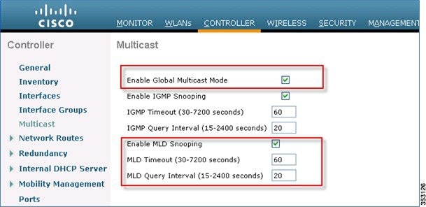
To configure Multicast for IPv6, perform the following steps:
Step 1![]() For IPv6 Multicast to be enabled, check the Enable Global Multicast Mode check box.
For IPv6 Multicast to be enabled, check the Enable Global Multicast Mode check box.
Step 2![]() Check the Enable MLD Snooping check box to support IPv6 forwarding decisions.
Check the Enable MLD Snooping check box to support IPv6 forwarding decisions.
Note![]() To enable MLD Snooping, you must enable Global Multicast Mode of the controller.
To enable MLD Snooping, you must enable Global Multicast Mode of the controller.
Step 3![]() Configure Multicast Mode:
Configure Multicast Mode:
a.![]() In the MLD Timeout text box, enter a value between 30 and 7200 seconds to set the MLD timeout.
In the MLD Timeout text box, enter a value between 30 and 7200 seconds to set the MLD timeout.
b.![]() In the MLD Query Interval text box, enter a value between 15 and 2400 seconds.
In the MLD Query Interval text box, enter a value between 15 and 2400 seconds.
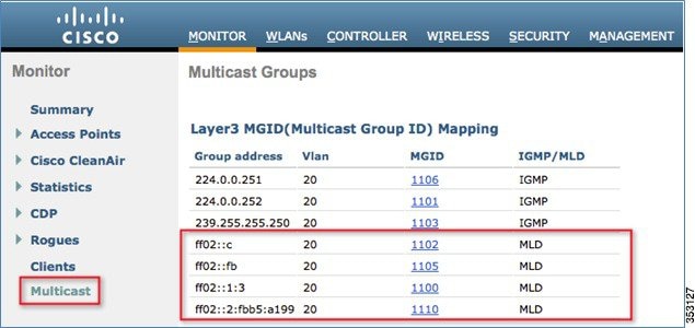
Step 4![]() To verify that IPv6 multicast traffic is being snooped, go to Monitor > Multicast. Note that both IPv4 (IGMP) and IPv6 (MLD) multicast groups are listed. Click MGID to view the wireless clients joined to that group address.
To verify that IPv6 multicast traffic is being snooped, go to Monitor > Multicast. Note that both IPv4 (IGMP) and IPv6 (MLD) multicast groups are listed. Click MGID to view the wireless clients joined to that group address.
Multicast Domain Name System – mDNS/Bonjour
Table 6-3 lists the Bonjour features from release 7.4 through 8.1.
Information About Multicast Domain Name System
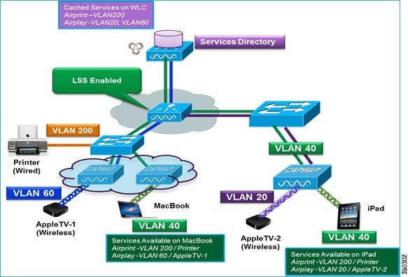
Multicast Domain Name System (mDNS) service discovery provides a way to announce and discover the services on the local network. The mDNS service discovery enables wireless clients to access Apple services such as Apple Printer and Apple TV advertised in a different Layer 3 network. mDNS performs DNS queries over IP multicast. mDNS supports zero-configuration IP networking.
Bonjour protocol operates on service announcements and service queries, which allow devices to ask and advertise specific applications such as:
- Printing Services
- File Sharing Services
- Remote Desktop Services
- iTunes File Sharing
- iTunes Wireless iDevice Syncing (in Apple iOS v5.0+)
- AirPlay offering the following streaming services:
–![]() Music broadcasting in iOS v4.2+
Music broadcasting in iOS v4.2+
–![]() Video broadcasting in iOS v4.3+
Video broadcasting in iOS v4.3+
–![]() Full screen mirroring in iOS v5.0+ (iPad2, iPhone4S or later)
Full screen mirroring in iOS v5.0+ (iPad2, iPhone4S or later)
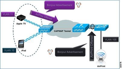
Each query or advertisement is sent to the Bonjour multicast address for delivery to all clients on the subnet. Apple’s Bonjour protocol relies on mDNS operating at UDP port 5353 and sent to the following reserved group addresses:
The addresses used by the Bonjour protocol are link-local multicast addresses, and thus are only forwarded to the local L2 domain. Routers cannot use multicast routing to redirect the traffic because the time to live (TTL) is set to one, and link-local multicast is meant to stay local by design.
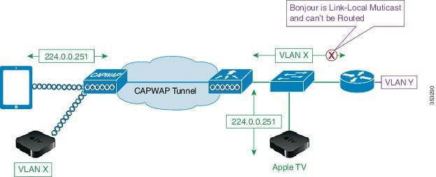
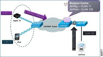
To address this issue, Cisco WLC acts as a Bonjour Gateway. The WLC listens for Bonjour services and by caching those Bonjour advertisements (AirPlay, AirPrint, and so on) from the source/host, for example AppleTV, it responds back to Bonjour clients when a request for service is initiated. The following illustrates this process:
Step 1![]() The controller listens for the bonjour services.
The controller listens for the bonjour services.
Step 2![]() The controller cache those bonjour services.
The controller cache those bonjour services.
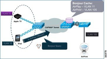
Step 3![]() The controller listens for the client queries for services.
The controller listens for the client queries for services.
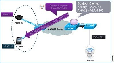
Step 4![]() The controller sends a unicast response to the client queries for bonjour services.
The controller sends a unicast response to the client queries for bonjour services.
Location Specific Services
The processing of mDNS service advertisements and mDNS query packets support Location Specific Services (LSS). All the valid mDNS service advertisements that are received by the controller are tagged with the MAC address of the AP that is associated with the service advertisement from the service provider while inserting the new entry into the service provider database. The response formulation to the client query filters the wireless entries in the service provider database using the MAC address of the AP associated with the querying client. The wireless service provider database entries are filtered based on the AP-NEIGHBOR-LIST if LSS is enabled for the service. If LSS is disabled for any service, the wireless service provider database entries are not filtered when they respond to any query from a wireless client for the service.
LSS applies only to wireless service provider database entries. There is no location awareness for wired service provider devices.
The status of LSS cannot be enabled for services with ORIGIN set to wired and vice versa.
mDNS AP
The mDNS AP feature allows the controller to have visibility of wired service providers that are on VLANs not visible to the controller. You can configure any AP as an mDNS AP and enable the AP to forward mDNS packets to the controller. VLAN visibility on the controller is achieved by APs that forward the mDNS advertisements to the controller. The mDNS packets between the AP and the controller are forwarded in Control and Provisioning of Wireless Access Points (CAPWAP) data tunnel that is similar to the mDNS packets from a wireless client. Only CAPWAP v4 tunnels are supported. APs can be in either the access port or the trunk port to learn the mDNS packets from the wired side and forward them to the controller. You can use the configurable knob that is provided on the controller to start or stop mDNS packet forwarding from a specific AP. You can also use this configuration to specify the VLANs from which the AP should snoop the mDNS advertisements from the wired side. The maximum number of VLANs that an AP can snoop is 10.
If the AP is in the access port, you should not configure any VLANs on the AP to snoop. The AP sends untagged packets when a query is to be sent. When an mDNS advertisement is received by the mDNS AP, the VLAN information is not passed on to the controller. The service provider's VLAN that is learned through the mDNS AP's access VLAN is maintained as 0 in the controller.
By default, the mDNS AP snoops in native VLAN. When an mDNS AP is enabled, native VLAN snooping is enabled by default and the VLAN information is passed as 0 for advertisements received on the native VLAN.
The mDNS AP feature is supported only on local mode and monitor mode APs. The mDNS AP configuration is retained on those mDNS APs even if global mDNs snooping is disabled. If an mDNS AP is reset or associated with the same controller or another controller, one of the following occurs:
- If the global snooping is disabled on the controller, a payload is sent to the AP to disable mDNS snooping.
- If the global snooping is enabled on the controller, the configuration of the AP before the reset or the association procedure is retained.
The process flow for the mDNS AP feature is as follows:
Uplink (Wired infrastructure to AP to Controller)
1.![]() Receives the 802.3 mDNS packet on configured VLANs.
Receives the 802.3 mDNS packet on configured VLANs.
2.![]() Forwards the received mDNS packet over CAPWAP.
Forwards the received mDNS packet over CAPWAP.
3.![]() Populates multicast group ID (MGID) based on the received VLAN.
Populates multicast group ID (MGID) based on the received VLAN.
Downlink (Controller to AP to Wired Infrastructure)
1.![]() Receives an mDNS query over CAPWAP from the controller.
Receives an mDNS query over CAPWAP from the controller.
2.![]() Forwards the query as 802.3 packet to wired infrastructure.
Forwards the query as 802.3 packet to wired infrastructure.
3.![]() The VLAN is identified from dedicated MGIDs.
The VLAN is identified from dedicated MGIDs.
Restrictions for Configuring Multicast DNS
- mDNS over IPv6 is not supported.
- mDNS is not supported on access points in FlexConnect mode in a locally switched WLAN and mesh access points.
- mDNS is not supported on remote LANs.
- mDNS is not supported on Cisco AP 1240 and AP 1130.
- Third party mDNS servers or applications are not supported on the Cisco WLC using the mDNS feature. Devices that are advertised by the third party servers or applications are not populated on the mDNS service or device table correctly on the Cisco WLC.
- In a Layer2 network, if Apple servers and clients are in the same subnet, mDNS snooping is not required on the Cisco WLC. However, this relies on the switching network to work. If you use switches that do not work as expected with mDNS snooping, you must enable mDNS on the Cisco WLC.
- Video is not supported on Apple iOS 6 with WMM in enabled state.
- mDNS APs cannot duplicate the same traffic for the same service or VLAN.
- DLSS filtering is restricted to only wireless services.
- The LSS, mDNS AP, Priority MAC address, and origin-based discovery features cannot be configured using the controller GUI.
- mDNS-AP feature is not supported in CAPWAP V6.
- DISE dynamic mDNS policy mobility is not supported.
- mDNS user profile mobility is not supported in guest anchors.
- Apple devices such as iPads and iPhones can discover Apple TV through Bluetooth. This might result in Apple TVs being visible to end users. Because Apple TVs are not supported on mDNS access policy, Cisco recommends you to disable Bluetooth on Apple TVs.
Introduction to Bonjour Policies and New Requirements
Bonjour gateway snoops and caches Bonjour services across VLANs and periodically refreshes the services. WLC acts as a proxy for all Bonjour services published by wireless and wired devices. Prior to release 8.0, Bonjour gateway had inadequate capabilities to filter cached wired / wireless service instances based on the credentials of the querying client and its location.
With introduction of the Bonjour policies in the release 8.0, the administrator can configure to identify who uses the Bonjour service instances and in what location (all this applies to the same WLAN). With introduction of the Bonjour policies, the administrator does not need to create multiple WLANs to select which services are allowed or should be used on specific WLAN. Based on user 802.1x authentication, the AAA server or ISE can be configured to return USER-ROLE or BONJOUR-PROFILE in the form of the “CISCO-AV-PAIR”. This value gets plumbed into the policy created on the wireless controller. Based on the user authentication, a configured policy and profile are applied to a specific user on the same WLAN.
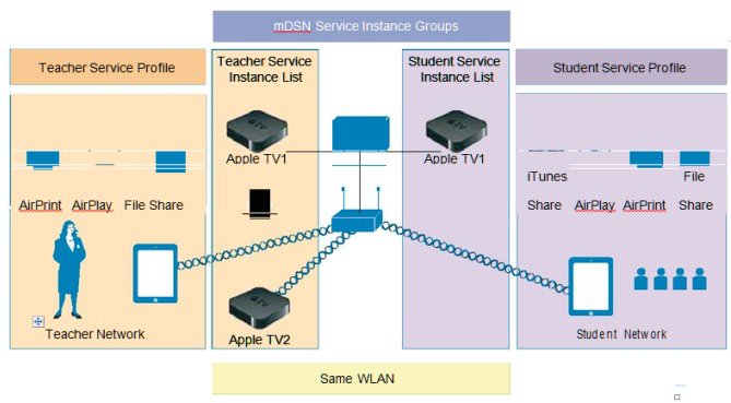
As mentioned in the figure above, improvements to Bonjour services are made. Bonjour policies are introduced to allow per service instance (MAC address) configuration that mandates how the service instance is shared, which is articulated as follows:
- Service instance is shared with whom (user-id).
- Service instance is shared with which role/s (client-role).
- Location where the Service Instance allowed to be accessed (Client Location)
This configuration can be applied to wired and wireless service instances, and the response to any query will solely be based on the policy configured for each service instance. This allows selective sharing of service instances based on the location, user-id, or role. As most service publishing devices are wired, this allows filtering of wired services at par with wireless service instances. While mDNS profile associated with the client checks for service type being queried before responding to the query, the access policy further allows filtering of specific service instances based on querying client location, role, or user-id.
With Bonjour access policy, there are two levels of filtering the client queries, which are as follows:
- At the service type level by using the mDNS profile.
- At the service instance level using the access policy associated with the service instance.
A service instance or a set of service instances discovered and cached by the WLC can be associated with an access policy filter, which acts like a lens that determines which clients and what kind of client context (role or user-id) can see and access the service instance.
Note![]() Service instances that are not configured with any access policy will be mapped to the default access policy, which allows only the administrator user role, by default, to receive the service instances. Additional users can be configured and added in the default policy.
Service instances that are not configured with any access policy will be mapped to the default access policy, which allows only the administrator user role, by default, to receive the service instances. Additional users can be configured and added in the default policy.
- Bonjour access policy filters can be configured for specific service instances identified by the MAC address of the devices publishing the services.
- Bonjour access policy is associated with a service group name that contains one or more MAC addresses of the devices publishing the Bonjour services.
- The service group name is then attached to the service instance when it is discovered and cached at the WLC.
- While traversing the list of service instances in response to a client query, each instance will be evaluated to verify if the querying client location, role, or user-id are allowed access to the service instance before including the same in the response.
If the same MAC address is configured in multiple service groups, it means the service instance will be associated with all the service group names that are configured with this MAC address. All the access policies associated with the MAC addressee’s service group names will be evaluated until the decision is to include the service instance. Currently, a maximum of five service groups are supported for a single MAC address. Service group configurations can be done even when mDNS snooping is disabled or offline, and the access policy comes into effect when the services are discovered. It can also be done dynamically when snooping is already enabled.
Bonjour Service Groups
A service group name can be associated with a set of MAC addresses. The maximum MAC addresses that can be configured for any service group is limited by the platform dependent global maximum number of service instances that can be discovered:
- In release 8.0, service limit: 6400 services on 2500, 5508, WiSM2, and vWLC and 16000 services on 7510 and 8510 UC controllers.
- In release 8.1, the service limit has changed to be more reflective of number of the AP licenses and clients supported and will change accordingly on 5508 and WiSM-2 controllers.
|
|
|
|
|---|---|---|
As shown in the table above, in release 8.1, 5508 controller is scaled down to support only 1000 services at full scale (500 APs and 7000 clients). With 80% scale (400 APs and 5400 users), the same 5508 controller supports 2400 services. Similarly, WiSM-2 supports 2000 services at full scale (1000 APs and 15000) and 4800 services at 80% scale. Number of Bonjour services remains unchanged on the 7500 and vWLC controllers. 5520 and 8500 series controllers support 16,000 services in release 8.1. On 2504 controller, the number of services drop significantly due to memory limitation. Therefore, Bonjour deployment should be limited to testing or very limited number of services. At full scale, it is not recommended to run Bonjour services on the 2504 controller with 8.1 software.
Wired and Wireless Location Specific Services
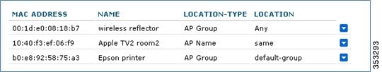
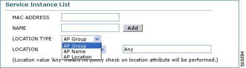
Each MAC address is configured with a unique name, which can be the service instance name, and the location of the MAC address for both wired and or wireless.
1.![]() Since flexibility is desired when configuring the location using the AP-NAME, AP-GROUP, or AP-LOCATION, the administrator has to configure the type of location that is desired. This configuration implies that only clients from the same location as that of the device publishing the service can access the service. As long as the global maximum limit of MAC addresses is not exceeded, any service group can configure as many MAC addresses as desired.
Since flexibility is desired when configuring the location using the AP-NAME, AP-GROUP, or AP-LOCATION, the administrator has to configure the type of location that is desired. This configuration implies that only clients from the same location as that of the device publishing the service can access the service. As long as the global maximum limit of MAC addresses is not exceeded, any service group can configure as many MAC addresses as desired.
In case of wireless service instances, the device location can change. Yet, if you want only those devices whose location is same as that of the service instance, the keyword “same” could be configured for such wireless service providers.
In case of wired services, the same location does not apply because wired clients do not get associated to the AP.
2.![]() If the keyword “Any” is configured for location, it implies that there is no location based filtering for the clients trying to access the device. This means the clients from any location can access the service subject to role and user-id credentials being allowed by the policy associated with the service group for that MAC address.
If the keyword “Any” is configured for location, it implies that there is no location based filtering for the clients trying to access the device. This means the clients from any location can access the service subject to role and user-id credentials being allowed by the policy associated with the service group for that MAC address.
3.![]() If the keyword “ap-name” is used, only clients associated to that AP can access the service instance.
If the keyword “ap-name” is used, only clients associated to that AP can access the service instance.
Note![]() Location validation is implicit and will be the first level of access policy filtering even before ROLE and USER-ID credentials of the client are verified.
Location validation is implicit and will be the first level of access policy filtering even before ROLE and USER-ID credentials of the client are verified.
Table 6-4 depicts a possible policy configuration with the service group named AppleTV-teachers.
|
|
|
|
|
|
|---|---|---|---|---|
Device Access Policy Constructs and Rules
This section explains the access policy in terms of the client context attributes, its constructs, the rule components that make up of the policy, and how the rules and hence the policies are evaluated. This helps in deciding whether the given service instance should be included or not in the mDNS response for the client that made the mDNS query. Further, if multiple service instances are mapped to the same access policy, for a given mDNS query, the policy will be evaluated only once for all those instances which have the same access policy mapping to optimize the policy evaluation overhead for a given query.
Client Context Attributes in an mDNS Policy
Any client initiating an mDNS query can be associated with a set of attributes that describe the context of the client. The attributes, for example location, can change dynamically when the clients move to a different location. Only these enumerated attributes will be used to articulate a Bonjour access policy rule. The list of attributes and how they are fetched are detailed in Table 6-5. The user can formulate a rule by combining these attributes with logical OR operations and attach the rule to the policy. A policy is composed of a single rule, even though multiple rules can be provisioned.
Access Policy Rules
An access policy service group is identified by a name and is associated with just one rule.
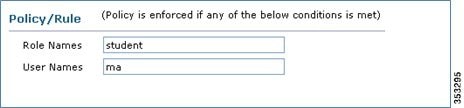
The rule is defined using the role or user-id (comma separated list). It implies that, a client, making an mDNS query, whose role is one of those listed in the policy roles or the client user-id is one of those listed in the user-id list, then access to the service instances is granted.
[ROLE=teacher, student] AND [USER-ID = John, Mike]
 Feedback