Quick Start Guide: Ceiling Mount Bezels for Cisco Aironet 1000 Series Lightweight Access Points
Bias-Free Language
The documentation set for this product strives to use bias-free language. For the purposes of this documentation set, bias-free is defined as language that does not imply discrimination based on age, disability, gender, racial identity, ethnic identity, sexual orientation, socioeconomic status, and intersectionality. Exceptions may be present in the documentation due to language that is hardcoded in the user interfaces of the product software, language used based on RFP documentation, or language that is used by a referenced third-party product. Learn more about how Cisco is using Inclusive Language.
- Updated:
- June 29, 2007
Chapter: Installation and Configuration
Installation and Configuration
This guide is designed to provide you with the information needed to mount Cisco Aironet 1000 Series 802.11a/b/g lightweight access points using the optional Ceiling-Mount Bezel Kit. These access points are part of the innovative Cisco Wireless LAN Solution (Cisco WLAN Solution), and require no manual configuration after they are mounted.
This document assumes that a site survey has been performed as described in the Deployment Guide: Cisco Aironet 1000 Series Lightweight Access Points, that access point locations and mounting options have been selected, and that you have one access point for each selected location.
After the site survey is done, you should have a map indicating the following:
•![]() Access point locations.
Access point locations.
•![]() Access point mounting options: hanging from a ceiling, in the ceiling plenum, projecting away from the wall, flat against the wall, or using the Ceiling-Mount Bezel Kit.
Access point mounting options: hanging from a ceiling, in the ceiling plenum, projecting away from the wall, flat against the wall, or using the Ceiling-Mount Bezel Kit.
•![]() Access point power options: power supplied by the AC-to-DC power supply orderable from the factory, or PoE from a network device or a PoE injector/hub (usually located in a wiring closet).
Access point power options: power supplied by the AC-to-DC power supply orderable from the factory, or PoE from a network device or a PoE injector/hub (usually located in a wiring closet).

When you do not have a map, make one so you can record the MAC addresses from each location and return them to the person who is planning or managing this wireless network.

Note ![]() When mounting these access points, be sure to maintain a 20 cm (8 in.) separation between the access point and bystanders to comply with FCC RF exposure regulations. Refer to "FCC Statements for Cisco Aironet 1000 Series Lightweight Access Points" section in the appropriate Cisco Aironet 1000 Series Lightweight Access Point Quick Start Guide.
When mounting these access points, be sure to maintain a 20 cm (8 in.) separation between the access point and bystanders to comply with FCC RF exposure regulations. Refer to "FCC Statements for Cisco Aironet 1000 Series Lightweight Access Points" section in the appropriate Cisco Aironet 1000 Series Lightweight Access Point Quick Start Guide.
For more details about access point installations, refer to the "Planning Notes" section in the appropriate Cisco Aironet 1000 Series Lightweight Access Point Quick Start Guide.
Important Guidelines
Note ![]() For information on planning and safety considerations, refer to Quick Start Guide: Cisco Aironet 1000 Series Lightweight Access Points with Internal Antennas or Quick Start Guide: Cisco Aironet 1000 Series Lightweight Access Points with External Antennas as appropriate.
For information on planning and safety considerations, refer to Quick Start Guide: Cisco Aironet 1000 Series Lightweight Access Points with Internal Antennas or Quick Start Guide: Cisco Aironet 1000 Series Lightweight Access Points with External Antennas as appropriate.
While these access points have been engineered for easy installation, there are some very important guidelines for installation:
•![]() Place the access points no more than 140 feet apart from each other. Placing access points farther apart almost always results in poor coverage.
Place the access points no more than 140 feet apart from each other. Placing access points farther apart almost always results in poor coverage.
•![]() Do not mount access points outside buildings.
Do not mount access points outside buildings.
•![]() Do not mount access points on building perimeter walls unless the operator wants to provide coverage outside the building.
Do not mount access points on building perimeter walls unless the operator wants to provide coverage outside the building.
•![]() Be sure that plenum-mounted access points are powered using Power over Ethernet (PoE) and use only the metal brackets (not the Ceiling-Mount Base or the Hanging-Ceiling Clips) to comply with safety regulations.
Be sure that plenum-mounted access points are powered using Power over Ethernet (PoE) and use only the metal brackets (not the Ceiling-Mount Base or the Hanging-Ceiling Clips) to comply with safety regulations.
•![]()

Be sure that access points are installed vertically. installing access points vertically either standing up in a plenum or hanging from a ceiling, creates the largest coverage area per access point. Hanging access points from the ceiling provides the best RF coverage.
•![]()
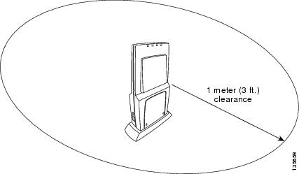
Do not mount access point antennas within one meter (3 ft.) of any metal obstructions. the rf waves from access points are blocked and/or reflected by metal objects such as metal HVAC ducts, conduit, pipes, bookcases, elevator shafts, stairwells, and metal walls. Refer to the Deployment Guide: Cisco Aironet 1000 Series Lightweight Access Point Before mounting access points near metal obstructions.
•![]() When mounting access points in the corner of a right-angle hallway intersection, mount the access point at a 45-degree angle to the two hallways. the access point internal antennas are not omnidirectional and cover a larger area when mounted this way.
When mounting access points in the corner of a right-angle hallway intersection, mount the access point at a 45-degree angle to the two hallways. the access point internal antennas are not omnidirectional and cover a larger area when mounted this way.
When access point is configured with an IP address and is moved to a different IP segment, it attempts to join a Cisco Wireless LAN Controller. If it is unable to join a Cisco Wireless LAN Controller after a number of attempts, it does an arp for the default configured gateway. If the Cisco Aironet 1000 Series lightweight access point is on the wrong subnet, it will not be able to resolve the gateway arp and it will attempt to contact a DHCP server. This is the access point IP address fallback feature. However, if the destination IP segment does not have a DHCP server, the access point retains its original IP address and can never join the network.
Collecting Required Tools and Supplies
•![]() One access point per location.
One access point per location.
•![]() One optional access point Ceiling-Mount Bezel Kit for each location.
One optional access point Ceiling-Mount Bezel Kit for each location.
•![]() Optional AC-to-DC external power supplies, factory-orderable. Note that this option requires the power cable to be run through the plenum in a metal conduit to meet safety requirements.
Optional AC-to-DC external power supplies, factory-orderable. Note that this option requires the power cable to be run through the plenum in a metal conduit to meet safety requirements.
•![]() Map showing access point locations and mounting and power options.
Map showing access point locations and mounting and power options.
•![]() Large razor knife or keyhole saw for cutting ceiling tile.
Large razor knife or keyhole saw for cutting ceiling tile.
•![]() Screwdrivers and ladder.
Screwdrivers and ladder.
•![]() CAT-5 (or higher) cables to connect the access point locations and any other network device.
CAT-5 (or higher) cables to connect the access point locations and any other network device.
•![]() Optional wire to secure each access point inside the ceiling.
Optional wire to secure each access point inside the ceiling.
Continue with "Pre Installation Configuration."
Pre Installation Configuration
Following these procedures will ensure that your installation and initial operation go smoothly.
Refer to the appropriate Cisco Aironet 1000 Series Lightweight Access Point Quick Start Guide for instructions.
Continue with "Installing the Ceiling-Mount Bezel Kit and Access Point."
Installing the Ceiling-Mount Bezel Kit and Access Point
On your map, you should have the Cisco Aironet 1000 Series lightweight access point locations, mounting options, and power options.
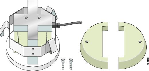
The Ceiling-Mount Bezel kit consists of the following components:
•![]() Installation Bracket with attached tension adjusters
Installation Bracket with attached tension adjusters
•![]() Bezel (left and right halves)
Bezel (left and right halves)
•![]() Bezel installation screws (2)
Bezel installation screws (2)
Figure 1 Factory-Orderable Ceiling-Mount Bezel Kit Components
Step 1 ![]() Find the required mounting locations.
Find the required mounting locations.
Step 2 ![]() When possible, remove the ceiling tile in which the kit is to be mounted.
When possible, remove the ceiling tile in which the kit is to be mounted.
Step 3 ![]() Using the bracket as a template, trace the round shape of the Installation Bracket onto the plenum side of the tile or drywall. It is a circle with a diameter of 7 inches (19 cm).
Using the bracket as a template, trace the round shape of the Installation Bracket onto the plenum side of the tile or drywall. It is a circle with a diameter of 7 inches (19 cm).
Step 4 ![]() Using the large razor knife or keyhole saw, cut out the hole you have just traced.
Using the large razor knife or keyhole saw, cut out the hole you have just traced.
Step 5 ![]() Insert the Installation Bracket into the hole from the plenum side. Be sure the three tension holders grip the tile or drywall, as shown in the following figure.
Insert the Installation Bracket into the hole from the plenum side. Be sure the three tension holders grip the tile or drywall, as shown in the following figure.
Step 6 ![]()
Step 7 ![]() From the room side of the tile, slip the Cisco Aironet 1000 Series lightweight access point into the center of the bezel.
From the room side of the tile, slip the Cisco Aironet 1000 Series lightweight access point into the center of the bezel.
Note ![]() When there are external antenna connectors, be sure they fit into the cutout on the mounting bracket.
When there are external antenna connectors, be sure they fit into the cutout on the mounting bracket.
Step 8 ![]() Using the screws provided with the access point, secure the access point to the Installation Bracket the from the plenum side of the tile or drywall. If the screw holes on the access points are not aligned, remove the access point, turn it, and re-insert it into the bracket.
Using the screws provided with the access point, secure the access point to the Installation Bracket the from the plenum side of the tile or drywall. If the screw holes on the access points are not aligned, remove the access point, turn it, and re-insert it into the bracket.
Step 9 ![]()
Step 10 ![]() From the ceiling side of the tile or drywall, use one of the provided screws to attach one half of the cover bezel. Do not tighten the screw.
From the ceiling side of the tile or drywall, use one of the provided screws to attach one half of the cover bezel. Do not tighten the screw.
Step 11 ![]() Snap the other half of the bezel into the first half and attach it with the other provided screw. Do not tighten the screw.
Snap the other half of the bezel into the first half and attach it with the other provided screw. Do not tighten the screw.
Step 12 ![]() Tighten the bezel screws so that the bezel is firmly attached around the access point.
Tighten the bezel screws so that the bezel is firmly attached around the access point.
Note ![]() Be sure that the bracket and bezel are snug, but not so tight that the access point cannot be rotated from the ceiling side.
Be sure that the bracket and bezel are snug, but not so tight that the access point cannot be rotated from the ceiling side.
Figure 2 Cisco Aironet 1000 Series Lightweight Access Point Installed in Bezel
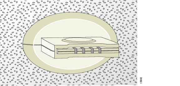
Step 13 ![]() For further adjustment, use the three tension holders on the plenum side of the tile or drywall by loosening the screw, adjusting the tension holder and re-tightening the screw. The following figure shows the tension holder adjustment screw locations.
For further adjustment, use the three tension holders on the plenum side of the tile or drywall by loosening the screw, adjusting the tension holder and re-tightening the screw. The following figure shows the tension holder adjustment screw locations.
Step 14 ![]() Reposition the ceiling tile into which you have installed the Ceiling-Mount Bezel kit and the access point into the ceiling.
Reposition the ceiling tile into which you have installed the Ceiling-Mount Bezel kit and the access point into the ceiling.
Step 15 ![]() To ensure that the access point does not fall from the ceiling, you can attach a wire from the metal installation bracket to any secure part of the building structure.
To ensure that the access point does not fall from the ceiling, you can attach a wire from the metal installation bracket to any secure part of the building structure.
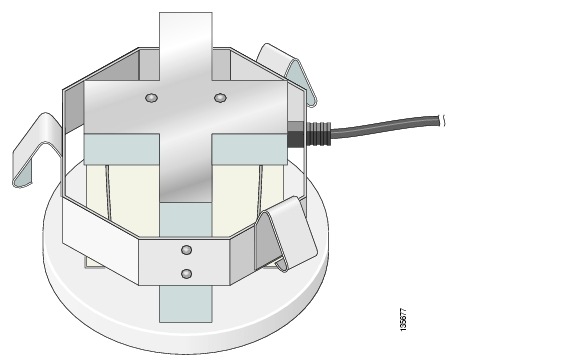
Step 16 ![]() Route the CAT-5, Ethernet cable and optional power supply to where they can plug into the access point. Be sure to leave about 6 inches (15 cm) of slack in the cables for future modifications. Note that using an optional External Power Supply instead of PoE requires that the power supply cable be fully enclosed in a metal conduit to meet safety requirements.
Route the CAT-5, Ethernet cable and optional power supply to where they can plug into the access point. Be sure to leave about 6 inches (15 cm) of slack in the cables for future modifications. Note that using an optional External Power Supply instead of PoE requires that the power supply cable be fully enclosed in a metal conduit to meet safety requirements.
Figure 3 Cable Plugged into the Cisco Aironet 1000 Series Lightweight Access Point as Viewed from the Plenum Side.
Note ![]() Be sure the cables are routed away from the access point antennas.
Be sure the cables are routed away from the access point antennas.
Note ![]() When the access point is powered up and is associated with a Cisco Wireless LAN Controller (Green Power and Yellow 802.11b/g and/or 802.11a LEDs lit), the access point begins broadcasting its beacon signals. When this happens, complete the installation as quickly as possible to remove yourself from within 8 inches (20 cm) of the access point to comply with FCC RF radiation exposure guidelines.
When the access point is powered up and is associated with a Cisco Wireless LAN Controller (Green Power and Yellow 802.11b/g and/or 802.11a LEDs lit), the access point begins broadcasting its beacon signals. When this happens, complete the installation as quickly as possible to remove yourself from within 8 inches (20 cm) of the access point to comply with FCC RF radiation exposure guidelines.
You have installed the access point and Ceiling-Mount Bezel Kit.
Repeat "Installing the Ceiling-Mount Bezel Kit and Access Point" for each access point location, and then continue with the appropriate Cisco Aironet 1000 Series Lightweight Access Point Quick Start Guide.
 Feedback