Cisco SRST SNMP MIB Release 3.4 Guide
Bias-Free Language
The documentation set for this product strives to use bias-free language. For the purposes of this documentation set, bias-free is defined as language that does not imply discrimination based on age, disability, gender, racial identity, ethnic identity, sexual orientation, socioeconomic status, and intersectionality. Exceptions may be present in the documentation due to language that is hardcoded in the user interfaces of the product software, language used based on RFP documentation, or language that is used by a referenced third-party product. Learn more about how Cisco is using Inclusive Language.
- Updated:
- July 12, 2010
Chapter: Cisco SRST SNMP MIB Support
- Overview
- Limitations
- Prerequisites
- Configuration
- SNMP Overview
Cisco SRST SNMP MIB Support
Survivable Remote Site Telephony (SRST) Cisco IOS feature is used for the remote office routers that support from 24 to 720 users in a centralized CallManager processing environment, to back up IP phone calls and provide 911 emergency access by the public switched telephone network (PSTN). Any SRST user can leverage SRST MIBs for better management with Simple Network Management Protocol (SNMP) support.
Feature History of the Cisco SRST MIB Feature
|
|
|
12.4(4)T |
This feature was introduced on the 12.4(4)T |
Finding Support Information for Platforms and Cisco IOS Software Images
Use Cisco Feature Navigator to find information about platform support and Cisco IOS software image support. Access Cisco Feature Navigator at http://www.cisco.com/go/fn. You must have an account on Cisco.com. If you do not have an account or have forgotten your username or password, click Cancel at the login dialog box and follow the instructions that appear.
Overview
The SRST 3.4 component of Cisco IOS is not capable of participating in network management using SNMP. The SRST 3.4 effort is to make these components SNMP visible and provide necessary network management functions. This Cisco IOS feature can be used in the deployed customer scenarios that use SNMP managers. The Cisco IOS SNMP Agent can provide the following features for the SRST modules:
•![]() Generate notifications/traps for various functionality failures
Generate notifications/traps for various functionality failures
•![]() Provide objects that help monitor performance/load of some of the key features
Provide objects that help monitor performance/load of some of the key features
•![]() Provide detailed configurations for help in fault isolation.
Provide detailed configurations for help in fault isolation.
•![]() Provide the active registrations of IP phones and Session Initiation Protocol (SIP) phones
Provide the active registrations of IP phones and Session Initiation Protocol (SIP) phones
•![]() Publish statistics on Ephone lines and SIP phone lines
Publish statistics on Ephone lines and SIP phone lines
•![]() Provide ability to mask/unmask notification
Provide ability to mask/unmask notification
SRST 3.4 does not have product-specific network management capabilities. The SRST MIB addresses SNMP Management Information Base (MIB) development for generating asynchronous exception notifications/traps, displaying configurations, and monitoring performance for IP telephony management purposes.
The SRST feature provides emergency back up IP phone call capabilities, as shown in Figure 1-1.
Figure 1-1 SRST Router Deployment with Network Management Components
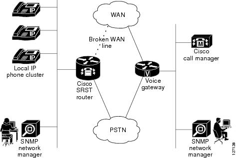
SRST provides backup redundancy for broadband deployment of IP telephony to small branch offices. It can be used if Cisco CallManager is no longer in service due to a loss of WAN connectivity. SRST continues to provide basic call processing and IP telephony service to phones that fall back to SRST.
The CISCO-SRST-MIB defines managed objects that pertain to SRST, SIP Registrar, and SIP phones.
The CISCO-SRST-MIB has dependency on existing Cisco IOS MIBs, especially on the CISCO-CCME-MIB and the CISCO-VOICE-DIAL-CONTROL-MIB.
All of these MIBs are accessible from SNMP management software running on external SNMP managers.
Design of the CISCO-SRST-MIB
The CISCO-SRST-MIB enables you to display configurations and monitor and send traps and asynchronous notifications to the SNMP management applications.
The CISCO-SRST-MIB approach offers the following advantages over the CLI command approach:
•![]() A more efficient use of network bandwidth
A more efficient use of network bandwidth
•![]() Greater interoperability among vendors because standard SNMP protocols are used
Greater interoperability among vendors because standard SNMP protocols are used
The following paragraphs describe the CISCO-SRST-MIB structure.
Structure
The Structure of Management Information (SMI) is represented conceptually by a tree hierarchy. Branches along the tree have short text strings and integers to identify them. Text strings describe object names, and integers allow computer software to encode compact representations of the names.
The CISCO-SRST-MIB is part of the Cisco management group, which is part of private.enterprise.cisco.ciscoMgmt.
The CISCO-SRST-MIB structure is further divided into the following groups:
SRST MIB Groups
ciscoSrstMIBNotifications
ciscoSrstMIBObjects
ciscoSrstMIBConformance
The CISCO-SRST-MIB structure further is divided into the following subgroups:
SRST MIB object groups
csrstConf
csrstNotifInfo
csrstSipConf
csrstActiveStats
csrstMIBNotifs
CISCO-SRST-MIB, which is uniquely identified by the number 441
Therefore the ciscoSrstMIB is1.3.6.1.4.1.9.9.441
Objects in the CISCO-SRST-MIB can be identified by either of the following methods.
•![]() The object identifier is 1.3.6.1.4.1.9.9.441<SRST MIB-variable>
The object identifier is 1.3.6.1.4.1.9.9.441<SRST MIB-variable>
•![]() The object name is iso(1).org(3).dod(6).internet(1).private(4).enterprise(1).cisco(9).ciscoMgmt(9)
The object name is iso(1).org(3).dod(6).internet(1).private(4).enterprise(1).cisco(9).ciscoMgmt(9)
.ciscoSrstMIB(441).<MIB-variable>
Figure 1-2 shows the position of the CISCO-SRST-MIB in the Internet MIB hierarchy.
Figure 1-2 CISCO-SRST-MIB Tree Structure

CISCO-SRST-MIB Features
The SRST 3.4 features that are supported by the CISCO-SRST-MIB are:
•![]() SRST configuration
SRST configuration
•![]() Ephone registrations
Ephone registrations
•![]() Ephone directory number (DN) (multiple lines per phone, multiple-line appearance per phone)
Ephone directory number (DN) (multiple lines per phone, multiple-line appearance per phone)
•![]() Huntstop (alias, SIP number list, between DNs)
Huntstop (alias, SIP number list, between DNs)
•![]() Class of Restriction (COR)
Class of Restriction (COR)
•![]() Translation Rule
Translation Rule
•![]() Music on Hold (MoH) (flash, multicast)
Music on Hold (MoH) (flash, multicast)
•![]() Call-forward
Call-forward
•![]() Phone number alias
Phone number alias
•![]() Voicemail number
Voicemail number
•![]() Dial-plan pattern
Dial-plan pattern
•![]() User-locale information
User-locale information
•![]() Secondary-dial tone
Secondary-dial tone
•![]() Ringing timeout
Ringing timeout
•![]() Date format
Date format
•![]() Dual-line mode
Dual-line mode
•![]() Customized system message
Customized system message
•![]() Consultative call transfer
Consultative call transfer
•![]() Interactive Voice Response (IVR) Application
Interactive Voice Response (IVR) Application
Table 1-1 lists the objects provided in the CISCO-SRST-MIB. Table 1-2 lists the notifications/traps provided in the CISCO-SRST-MIB.
Common Tables
The following tables are common to both the CCME and SRST MIBs:
•![]() ccmeCorConfTable
ccmeCorConfTable
•![]() ccmeDialplanPatternTable
ccmeDialplanPatternTable
•![]() ccmeTransferPatternTable
ccmeTransferPatternTable
•![]() ccmeEphoneBtnDNAssocConfTable
ccmeEphoneBtnDNAssocConfTable
•![]() ccmeEphoneActTable
ccmeEphoneActTable
•![]() ccmeEphoneDnChStatsHistoryTable
ccmeEphoneDnChStatsHistoryTable
•![]() ccmeEphoneConfTable
ccmeEphoneConfTable
Common Notifications/Traps
The following notifications/traps are common to both the CCME and SRST MIBs:
•![]() ccmeEphoneUnRegistrationThresholdExceed
ccmeEphoneUnRegistrationThresholdExceed
•![]() ccmeEPhoneRegFailed
ccmeEPhoneRegFailed
•![]() ccmeEPhoneDeceased
ccmeEPhoneDeceased
Common Objects
The following objects are common to both the CCME and SRST MIBs:
•![]() ccmeEphoneUnRegistrationThreshold
ccmeEphoneUnRegistrationThreshold
•![]() ccmeEphoneTot
ccmeEphoneTot
•![]() ccmeEphoneTotalRegistered
ccmeEphoneTotalRegistered
•![]() ccmeEphoneCallLegs
ccmeEphoneCallLegs
Common Tables
The tables listed in Table 1-3 are common to both the CCME and SRST MIBs.
Dependencies of the SRST MIB
When using an SRST router, you can get information regarding Ephones, Ephone-dns, and related statistics from the CCME MIB. For example:
•![]() To retrieve the total number of SCCP phones registered (EphoneTotalRegistered) to the SRST router, get the total number of SCCP registered from the CCME MIB.
To retrieve the total number of SCCP phones registered (EphoneTotalRegistered) to the SRST router, get the total number of SCCP registered from the CCME MIB.
•![]() To retrieve the total number of SCCP call legs (EphoneCallLegs) accumulated on the SRST router, get the total number of SCCP call legs from the CCME MIB.
To retrieve the total number of SCCP call legs (EphoneCallLegs) accumulated on the SRST router, get the total number of SCCP call legs from the CCME MIB.
•![]() To monitor the SCCP phone activities, retrieve the ccmeEphoneActTable from the CCME MIB.
To monitor the SCCP phone activities, retrieve the ccmeEphoneActTable from the CCME MIB.
Limitations
Be aware of the following design limitations when implementing the CISCO-SRST-MIB:
•![]() Configuring objects is not provided through SNMP.
Configuring objects is not provided through SNMP.
•![]() No password or encrypted objects are provided.
No password or encrypted objects are provided.
•![]() Objects that are not part of the CISCO-SRST-MIB are out of the scope of this MIB.
Objects that are not part of the CISCO-SRST-MIB are out of the scope of this MIB.
•![]() SIP phone details that cannot be seen by underlying Cisco IOS SRST layers, such as the Ethernet address, are not provided.
SIP phone details that cannot be seen by underlying Cisco IOS SRST layers, such as the Ethernet address, are not provided.
Performance Impact
The performance characteristics of the SRST SNMP module vary significantly depending on how often bulk data is requested by the SNMP managers.
SNMP bulk data can consume significant CPU and DRAM resources, and even network bandwidth. We recommend that management stations are to minimize the statistical sampling intervals as much as possible. Even though CISCO-SRST-MIB objects are grouped to reduce the unnecessary bulk data that can be fetched at a burst, the Cisco IOS SNMP agent does not enforce the data volume or the frequency at which SNMP managers make requests to the SNMP agent.
To reduce performance impact, the SRST gateway managers can use the traps provided by these MIBs by using asynchronous fault notification and traps to help isolate a fault.
There are few leaf objects, and they are light weighted and important (specified in active Group of the MIBs). They can be sampled at relatively short intervals, which would help gather the load on the CISCO-SRST-MIB components.
The Cisco IOS software supports SNMP versions 1, 2c, and 3 (SNMPv1, SNMPv2c, and SNMPv3). The SRST MIB is compliant with SNMPv2c and SNMPv3.
External SNMP managers are required; they issue SNMP queries and also accept SNMP notifications and traps. The SNMP managers include tools, such as basic Scotty command line tools, HP-OpenView, SunNet managers, IBM Netview, Tivoli, NetIQ, and so on.
To provide complete monitoring solutions, the SNMP managers can interface with existing Cisco IOS MIBs that address individual components and build a "schema" (or view) that helps monitor objects that suit their configuration or needs. For SRST related scenarios, the CISCO-VOICE-DIAL-CONTROL-MIB, various hardware interface MIBs, and the CISCO-CCM-MIB are available.
Prerequisites
The following must be configured for the CISCO-SRST-MIB to function:
•![]() Cisco CallManager Fallback must be configured on your system.
Cisco CallManager Fallback must be configured on your system.
•![]() An SNMP manager must be available on the network. For more information on configuring an SNMP server for use with a MIB, refer to the "Configuring SNMP Support" chapter of the Cisco IOS Configuration Fundamentals and Network Management Configuration Guide, Release 12.3. at the following URL:
An SNMP manager must be available on the network. For more information on configuring an SNMP server for use with a MIB, refer to the "Configuring SNMP Support" chapter of the Cisco IOS Configuration Fundamentals and Network Management Configuration Guide, Release 12.3. at the following URL:
http://www.cisco.com/univercd/cc/td/doc/product/software/ios122/122cgcr/ffun_c/fcfprt3/fcf014.htm
•![]() An SNMP Agent must be configured for the router on which the CISCO-SRST-MIB feature is to be used. Refer to the "Enabling the SNMP Agent" section in this document for more information.
An SNMP Agent must be configured for the router on which the CISCO-SRST-MIB feature is to be used. Refer to the "Enabling the SNMP Agent" section in this document for more information.
•![]() Ensure the traps are defined in the NMS software.
Ensure the traps are defined in the NMS software.
•![]() Ensure the alarm events are not put into "log only" mode and come up as an Alarm.
Ensure the alarm events are not put into "log only" mode and come up as an Alarm.
Supported Platforms for SRST 3.4
The SRST 3.4 feature is supported on the platforms listed in the following sections.
Cisco Voice Gateways
The SRST 3.4 feature is supported on the following voice gateways:
•![]() Cisco IAD24xx
Cisco IAD24xx
•![]() Cisco 17xx: 1751V and 1760
Cisco 17xx: 1751V and 1760
•![]() Cisco 2600XM: 261x XM, 262x XM, 265x XM, and 2691
Cisco 2600XM: 261x XM, 262x XM, 265x XM, and 2691
•![]() Cisco 3600: 3640, 3640A, and 3660
Cisco 3600: 3640, 3640A, and 3660
•![]() Cisco 37xx: 3725 and 3745
Cisco 37xx: 3725 and 3745
•![]() Catalyst 4500 with AGM
Catalyst 4500 with AGM
•![]() Cisco 7200
Cisco 7200
Cisco IP Phones
The SRST 3.4 feature is supported on the following Cisco IP phones:
•![]() Cisco IP Phone 7905 and 7905G
Cisco IP Phone 7905 and 7905G
•![]() Cisco IP Phone 7910G
Cisco IP Phone 7910G
•![]() Cisco IP Phone 7902G
Cisco IP Phone 7902G
•![]() Cisco IP Phone 7912G
Cisco IP Phone 7912G
•![]() Cisco IP Expansion Module 7914
Cisco IP Expansion Module 7914
•![]() Cisco IP Conference Station 7935
Cisco IP Conference Station 7935
•![]() Cisco IP Phone 7940 and 7940G
Cisco IP Phone 7940 and 7940G
•![]() Cisco IP Phone 7960 and 7960G
Cisco IP Phone 7960 and 7960G
•![]() Cisco VG248 Analog Phone Gateway Version 1.2(1) and higher
Cisco VG248 Analog Phone Gateway Version 1.2(1) and higher
•![]() Cisco VG224 Analog phone gateway
Cisco VG224 Analog phone gateway
Licenses
The following licences are required for SRST operation:
•![]() A base SRST feature license
A base SRST feature license
•![]() A phone seat license for each phone
A phone seat license for each phone
Depending on the platform used, the maximum number of ePhone licenses supported ranges from 24 to 240.
Configuration
To configure the SRST/CCME MIB feature, you should understanding the following concept.
Using SNMP and MIBs to Extract CISCO-SRST-MIB Information
SNMP has historically been used to collect network information. SNMP permits retrieval of critical information from network elements such as routers, switches, and workstations. The CISCO-SRST-MIB feature uses SNMP to gather remote site status information.
The CISCO-SRST-MIB feature allows remote site status data for the managed devices on your system to be retrieved by SNMP. You can specify retrieval of CISCO-SRST-MIB information from a managed device (for example, a router) either by entering commands on that managed device or by entering SNMP commands from the NMS workstation to configure the router by the MIB. If the CISCO-SRST-MIB information is configured from the network management system (NMS) workstation, no access to the router is required and all configuration can be performed by SNMP. The CISCO-SRST-MIB request for information is sent from an NMS workstation by SNMP to the router and is retrieved from the router. This information can then be stored or viewed, thus allowing CISCO-SRST-MIB information to be easily accessed and transported across a multivendor programming environment.
How to Configure the CISCO-SRST-MIB
This section contains the following procedures:
•![]() Enabling the SNMP Agent (required)
Enabling the SNMP Agent (required)
•![]() Verifying the Enabling of the SNMP Agent (optional)
Verifying the Enabling of the SNMP Agent (optional)
Enabling the SNMP Agent
The SNMP Agent for the SRST/CCME MIB is disabled by default. To enable the SNMP agent for the CISCO-SRST-MIB, perform the following steps:
|
|
|
|
|---|---|---|
Step 1 |
Prompt# telnet xxx.xxx.xxx.xxx |
Telnets to the router identified by the specified IP address |
Step 2 |
Router# enable |
Enters the enable mode. |
Step 3 |
Router# show running-config |
Displays the running configuration to determine if an SNMP agent is already running. If no SNMP information is displayed, continue with Step 4. If any SNMP information is displayed, you can modify the information or change it as needed. |
Step 4 |
Router# config terminal |
Enters global configuration mode. |
Step 5 |
Router(config)# snmp-server community xxxxxx RO |
Enables the read-only (RO) community string, where xxxxxx represents the read-only community string |
Step 6 |
Router(config)# snmp-server community xxxxxx RW |
Enables the read-write (RW) community string, where xxxxxx represents the read-write community string. |
Step 7 |
Router(config)# exit |
Exits global configuration mode and returns you to privileged EXEC mode. |
Step 8 |
Router# write memory |
Writes the modified configuration to nonvolatile memory (NVRAM), permanently saving the settings. |
Verifying the Enabling of the SNMP Agent
To verify that the SNMP agent has been enabled on a given network device, perform the following steps:
Step 1 ![]() Telnet to the target device:
Telnet to the target device:
Router# telnet xxx.xxx.xxx.xxx
where xxx.xxx.xxx.xxx represents the IP address of the target device.
Step 2 ![]() Establish the enable mode on the device:
Establish the enable mode on the device:
Router# enable
Step 3 ![]() Display the running configuration on the device and examine the output for any displayed SNMP information:
Display the running configuration on the device and examine the output for any displayed SNMP information:
Router# show running-config
...
...
snmp-server community public RO
snmp-server community private RW
Any "snmp-server" statement appearing in the output that takes the form shown above verifies that SNMP has been enabled on the specified device.
Configuration Examples
Configuration examples are provided in the following sections:
•![]() Complete SRST Configuration Example
Complete SRST Configuration Example
•![]() Monitoring SCCP Phone Statistics
Monitoring SCCP Phone Statistics
•![]() Retrieving SIP Phone Registrations
Retrieving SIP Phone Registrations
Complete SRST Configuration Example
The following is a complete configuration example for SRST. It is provided to give you an example of the commands used when configuring SRST.
SRST-Router#sh run
•![]()
•![]()
•![]()
!
hostname SRST-Router
!
•![]()
•![]()
•![]()
ip subnet-zero
ip cef
!
!
voice service voip
sip
registrar server expires max 600 min 60
!
!
voice class codec 1
codec preference 1 g711ulaw
codec preference 2 g729br8
!
!
!
!
!
!
!
voice register pool 1
id network 1.4.196.0 mask 255.255.255.0
proxy 1.4.196.1 monitor probe rtr
!
voice register pool 3
id network 1.4.4.1 mask 255.255.255.0
number 2 2020 preference 2
number 4 4040 preference 4
alias 2 2211 to 2222 preference 2
alias 4 4411 to 4444 preference 4
!
voice register pool 4
id network 1.4.199.1 mask 255.255.255.255
proxy 1.4.100.1
!
voice register pool 7
id mac 0002.0002.0002
number 3 3030 preference 3
number 10 10 preference 10
cor incoming eng 1 1000
cor incoming eng 3 3000
cor outgoing eng 4 4000
proxy 1.4.196.7 monitor probe rtr
alias 1 1012 to 1013 preference 2
alias 5 5012 to 5013 preference 4
!
!
!
!
!
!
!
!
interface FastEthernet0/0
ip address 1.4.196.1 255.255.0.0
no ip route-cache cef
no ip route-cache
no ip mroute-cache
duplex auto
speed auto
no cdp enable
!
interface FastEthernet0/1
ip address 3.0.0.1 255.255.255.0
no ip mroute-cache
duplex auto
speed auto
no keepalive
no cdp enable
!
interface Serial0/2:1
ip address 12.12.12.1 255.255.255.0
!
ip classless
ip route 0.0.0.0 0.0.0.0 1.4.0.1
ip route 4.0.0.0 255.255.255.0 FastEthernet0/0
ip route 223.255.254.0 255.255.255.0 1.4.0.1
ip route 223.255.254.254 255.255.255.255 FastEthernet0/0
!
no ip http server
!
snmp-server community public RW
snmp-server community test RW
snmp-server contact helloall
snmp-server host 1.4.198.78 SNMP
snmp-server host 1.4.198.78 SNMPv2c
no cdp run
arp 3.3.3.3 0000.0000.001a ARPA
!
!
tftp-server flash:P0S30202.bin
tftp-server flash:SIP000F23AD6FBC.cnf
tftp-server flash:SIPDefault.cnf
tftp-server flash:OS79XX.TXT
tftp-server flash:P0S3-04-1-00.bin
tftp-server flash:P00305000300.bin
!
control-plane
!
!
!
voice-port 0/3:2
no ignore rx-c-bit
no ignore rx-d-bit
condition tx-a-bit off
condition tx-b-bit invert
condition tx-c-bit on
!
voice-port 0/3:3
!
voice-port 4/0/0
!
voice-port 4/0/1
!
!
!
!
!
dial-peer cor custom
name test_shanmukh_member
name liz
!
!
dial-peer cor list test
!
dial-peer cor list name
!
dial-peer cor list eng
member liz
!
dial-peer cor list hr
!
!
dial-peer voice 2001 pots
destination-pattern 2001
!
dial-peer voice 9002 voip
corlist incoming eng
destination-pattern ....
session target ipv4:1.4.196.77
dtmf-relay h245-alphanumeric
ip qos dscp cs5 media
!
dial-peer voice 9003 voip
destination-pattern ....
session target ipv4:1.4.196.78
dtmf-relay h245-alphanumeric
ip qos dscp cs5 media
!
dial-peer voice 9001 voip
!
gateway
timer receive-rtp 1200
security password 1511021F0725 level endpoint
!
sip-ua
sip-server ipv4:1.4.196.1
!
!
call-manager-fallback
max-conferences 8 gain -6
limit-dn 7960 20
ip source-address 1.4.196.1 port 2000
max-ephones 10
max-dn 10
dialplan-pattern 2 2222 extension-length 2 extension-pattern 20 no-reg
dialplan-pattern 4 4444 extension-length 4 extension-pattern 4040
dialplan-pattern 5 5555 extension-length 2 extension-pattern 50
transfer-pattern 111 blind
transfer-pattern 202
transfer-pattern 301 blind
access-code bri 333 direct-inward-dial
access-code pri 44 direct-inward-dial
alias 1 1234 to 9988 huntstop
alias 2 2222 to 5552222
alias 4 4444 to 5554444
alias 8 8888 to 5558888
time-format 24
date-format yy-mm-dd
cor incoming eng default
cor incoming eng 1 2000
cor incoming eng 2 2000 - 2010
cor outgoing hr 1 1000
cor outgoing hr 2 2000
!
!
line con 0
exec-timeout 0 0
line aux 0
line vty 0 4
login
!
!
end
Configuring SRST Mode
Perform the following steps to configure SRST mode.
Step 1 ![]() Have Ephones registered to CME or CallManager before enabling SRST.
Have Ephones registered to CME or CallManager before enabling SRST.
Step 2 ![]() Have an Ephone-dn assigned to each Ephone.
Have an Ephone-dn assigned to each Ephone.
Step 3 ![]() Have a button associated with each Ephone-dn.
Have a button associated with each Ephone-dn.
Step 4 ![]() Configure and show call-manager-fallback.
Configure and show call-manager-fallback.
Step 5 ![]() Verify the response to show call-manager-fallback is similar to the following:
Verify the response to show call-manager-fallback is similar to the following:
SRST-Router#sh call-manager-fallback
CONFIG (Version=3.3)
=====================
Version 3.3
For on-line documentation please see:
www.cisco.com/univercd/cc/td/doc/product/access/ip_ph/ip_ks/index.htm
ip source-address 1.4.196.1 port 2000
max-ephones 10
max-dn 10
max-conferences 8 gain -6
dspfarm units 0
dspfarm transcode sessions 0
huntstop
dialplan-pattern 2 2222 extension-length 2 extension-pattern 20 no-reg
dialplan-pattern 4 4444 extension-length 4 extension-pattern 4040
dialplan-pattern 5 5555 extension-length 2 extension-pattern 50
access-code bri 333 direct-inward-dial
access-code pri 44 direct-inward-dial
time-format 24
date-format yy-mm-dd
timezone 0 Greenwich Standard Time
transfer-pattern 111 blind
transfer-pattern 202
transfer-pattern 301 blind
cor incoming eng default
cor incoming eng 1 2000
cor outgoing hr 1 1000
cor incoming eng 2 2000-2010
cor outgoing hr 2 2000
alias 1 1234 to 9988 huntstop
alias 2 2222 to 5552222
alias 4 4444 to 5554444
alias 8 8888 to 5558888
keepalive 30
timeout interdigit 10
timeout busy 10
timeout ringing 180
caller-id name-only: enable
Limit number of DNs per phone:
7910: 34
7935: 34
7936: 34
7940: 34
7960: 20
7970: 34
Log (table parameters):
max-size: 150
retain-timer: 15
local directory service: enabled.
Step 6 ![]() Simulate a link failure for Ephones to fall back to SRST mode.
Simulate a link failure for Ephones to fall back to SRST mode.
Step 7 ![]() Issue the following command to check call-manager-fallback configuration:
Issue the following command to check call-manager-fallback configuration:
getmany -v2c <ip addr> test csrstConf
Step 8 ![]() Verify the response to getmany is similar to the following:
Verify the response to getmany is similar to the following:
moki:1929> getmany -v2c 1.4.196.1 test csrstConf
csrstEnabled.0 = true(1)
csrstVersion.0 = 3.3
csrstIPAddressType.0 = ipv4(1)
csrstIPAddress.0 = 1.4.196.1
csrstPortNumber.0 = 2000
csrstMaxConferences.0 = 8
csrstMaxEphones.0 = 10
csrstMaxDN.0 = 10
csrstSipPhoneUnRegThreshold.0 = 480
csrstCallFwdNoAnswer.0 =
csrstCallFwdNoAnswerTo.0 = 180
csrstCallFwdBusy.0 =
csrstMohFilename.0 =
csrstMohMulticastAddrType.0 = ipv4(1)
csrstMohMulticastAddr.0 = 0.0.0.0
csrstMohMulticastPort.0 = 0
csrstVoiceMailNumber.0 =
csrstSystemMessagePrimary.0 =
csrstSystemMessageSecondary.0 =
csrstScriptName.0 =
csrstSecondaryDialTone.0 =
csrstTransferSystem.0 = blind(1)
csrstUserLocaleInfo.0 = us(11)
csrstDateFormat.0 = yymmdd(4)
csrstTimeFormat.0 = twentyFourHour(2)
csrstInterdigitTo.0 = 10
csrstBusyTo.0 = 10
csrstAlertTo.0 = 180
csrstXlateCalledNumber.0 = 0
csrstXlateCallingNumber.0 = 0
csrstAliasTag.0 = 1
csrstAliasTag.1 = 2
csrstAliasTag.2 = 4
csrstAliasTag.3 = 8
csrstAliasTag.4 = 2
csrstAliasTag.5 = 4
csrstAliasTag.6 = 1
csrstAliasTag.7 = 5
csrstAliasNumPattern.0 = 9988
csrstAliasNumPattern.1 = 5552222
csrstAliasNumPattern.2 = 5554444
csrstAliasNumPattern.3 = 5558888
csrstAliasNumPattern.4 = 2222
csrstAliasNumPattern.5 = 4444
csrstAliasNumPattern.6 = 1013
csrstAliasNumPattern.7 = 5013
csrstAliasAltNumber.0 = 1234
csrstAliasAltNumber.1 = 2222
csrstAliasAltNumber.2 = 4444
csrstAliasAltNumber.3 = 8888
csrstAliasAltNumber.4 = 2211
csrstAliasAltNumber.5 = 4411
csrstAliasAltNumber.6 = 1012
csrstAliasAltNumber.7 = 5012
csrstAliasPreference.0 = 0
csrstAliasPreference.1 = 0
csrstAliasPreference.2 = 0
csrstAliasPreference.3 = 0
csrstAliasPreference.4 = 2
csrstAliasPreference.5 = 4
csrstAliasPreference.6 = 2
csrstAliasPreference.7 = 4
csrstAliasHuntStopEnabled.0 = true(1)
csrstAliasHuntStopEnabled.1 = false(2)
csrstAliasHuntStopEnabled.2 = false(2)
csrstAliasHuntStopEnabled.3 = false(2)
csrstAliasHuntStopEnabled.4 = false(2)
csrstAliasHuntStopEnabled.5 = false(2)
csrstAliasHuntStopEnabled.6 = false(2)
csrstAliasHuntStopEnabled.7 = false(2)
csrstAccessCodeType.3 = bri(3)
csrstAccessCodeType.4 = pri(4)
csrstAccessCode.3 = 333
csrstAccessCode.4 = 44
csrstAccessCodeDIDEnabled.3 = true(1)
csrstAccessCodeDIDEnabled.4 = true(1)
csrstLimitDNType.1 = ipPhone7910(1)
csrstLimitDNType.2 = ipPhone7935(2)
csrstLimitDNType.3 = ipPhone7940(3)
csrstLimitDNType.4 = ipPhone7960(4)
csrstLimitDN.1 = 34
csrstLimitDN.2 = 34
csrstLimitDN.3 = 34
csrstLimitDN.4 = 20
csrstNotificationEnabled.0 = false(2)
Enabling Traps in SRST Mode
To enable traps in SRST mode, perform the following steps:
Step 1 ![]() Issue the following command:
Issue the following command:
Setany -v2c <ip addr> test csrstNotificationEnabled.0 -i 1
Step 2 ![]() When the SRST has at least 1 SCCP phone with DN associated with it, an "SRST system state change up" trap is generated.
When the SRST has at least 1 SCCP phone with DN associated with it, an "SRST system state change up" trap is generated.
*Mar 10 23:13:15.632: SNMP: V1 Trap, ent ciscoMgmt.441, addr 1.4.196.1, gentrap 6,
spectrap 1
ciscoMgmt.441.2.2.2.1.2.1 = 2
ciscoMgmt.441.1.3.1.2.1 = 1
ciscoMgmt.441.2.2.2.2.2.1 = SRST system state change up
Monitoring SCCP Phone Statistics
To monitor SCCP phone statistics, perform the following steps:
Step 1 ![]() Register the Ephones to the SRST router.
Register the Ephones to the SRST router.
Step 2 ![]() Issue the following CLI command:
Issue the following CLI command:
Show ephone summary
Step 3 ![]() Verify the response to show Ephone summary is similar to the following:
Verify the response to show Ephone summary is similar to the following:
SRST-Router#sh ephone summary
ephone-1 Mac:000F.24BA.2C37 TCP socket:[1] activeLine:0 REGISTERED
mediaActive:0 offhook:0 ringing:0 reset:0 reset_sent:0 debug:0
IP:1.4.196.42 7912 keepalive 2 1:1 2:2 CM Fallback
ephone-2 Mac:0011.BBEF.7554 TCP socket:[2] activeLine:0 REGISTERED
mediaActive:0 offhook:0 ringing:0 reset:0 reset_sent:0 debug:0
IP:1.4.196.2 Telecaster 7960 keepalive 2 CM Fallback
ephone-3 Mac:000D.2808.427F TCP socket:[3] activeLine:0 REGISTERED
mediaActive:0 offhook:0 ringing:0 reset:0 reset_sent:0 debug:0
IP:1.4.196.3 Telecaster 7960 keepalive 1 CM Fallback
Max 10, Registered 3, Unregistered 0, Deceased 0, Sockets 3
ephone_send_packet process switched 0
Max Conferences 8 with 0 active (8 allowed)
Skinny Music On Hold Status
Active MOH clients 0 (max 480), Media Clients 0
No MOH file loaded
Step 4 ![]() Issue the following SNMP request:
Issue the following SNMP request:
Getmany -v2c <ip addr> test ccmeActiveStats
Step 5 ![]() Verify the response for the getmany request is similar to the following:
Verify the response for the getmany request is similar to the following:
moki:1931> getmany -v2c 1.4.196.1 test ccmeActiveStats
ccmeEphoneCallLegs.0 = 0
ccmeEphoneTot.0 = 3
ccmeEphoneTotRegistered.0 = 3
ccmeEphoneTotKeyPhConfigured.0 = 0
ccmeEphoneTotKeyPhRegistered.0 = 0
ccmeEphoneDeviceName.1 = SEP000F24BA2C37
ccmeEphoneDeviceName.2 = SEP000D2808427F
ccmeEphoneDeviceName.3 = SEP0011BBEF7554
ccmeEphoneRegState.1 = registered(1)
ccmeEphoneRegState.2 = registered(1)
ccmeEphoneRegState.3 = registered(1)
ccmeEphoneActiveDN.1 = 0
ccmeEphoneActiveDN.2 = 0
ccmeEphoneActiveDN.3 = 0
ccmeEphoneActivityStatus.1 = onhook(1)
ccmeEphoneActivityStatus.2 = onhook(1)
ccmeEphoneActivityStatus.3 = onhook(1)
ccmeEphoneKeepAliveCnt.1 = 3
ccmeEphoneKeepAliveCnt.2 = 4
ccmeEphoneKeepAliveCnt.3 = 3
ccmeEphonePendingReset.1 = false(2)
ccmeEphonePendingReset.2 = false(2)
ccmeEphonePendingReset.3 = false(2)
ccmeEphoneRegTime.1 =
ccmeEphoneRegTime.2 =
ccmeEphoneRegTime.3 =
ccmeEphoneCurrentFirmwareRev.1 = CP7912010200SCCP031023
ccmeEphoneCurrentFirmwareRev.2 = 7.0(2.0)
ccmeEphoneCurrentFirmwareRev.3 = 7.0(2.0)
ccmeEphonePreviousFirmwareRev.1 =
ccmeEphonePreviousFirmwareRev.2 =
ccmeEphonePreviousFirmwareRev.3 =
ccmeEphoneLastError.1 = Initialized
ccmeEphoneLastError.2 = CM-closed-TCP
ccmeEphoneLastError.3 = CM-closed-TCP
ccmeEphoneObservedType.1 = 7912
ccmeEphoneObservedType.2 = Telecaster 7960
ccmeEphoneObservedType.3 = Telecaster 7960
ccmeEphoneLoginStatus.1 = false(2)
ccmeEphoneLoginStatus.2 = false(2)
ccmeEphoneLoginStatus.3 = false(2)
ccmeEphoneDnDStatus.1 = false(2)
ccmeEphoneDnDStatus.2 = false(2)
ccmeEphoneDnDStatus.3 = false(2)
ccmeEphoneDebugStatus.1 = false(2)
ccmeEphoneDebugStatus.2 = false(2)
ccmeEphoneDebugStatus.3 = false(2)
ccmeEphoneMediaActive.1 = false(2)
ccmeEphoneMediaActive.2 = false(2)
ccmeEphoneMediaActive.3 = false(2)
ccmeEphoneTAPIClient.1 = false(2)
ccmeEphoneTAPIClient.2 = false(2)
ccmeEphoneTAPIClient.3 = false(2)
ccmeEphoneMediaCapability.1 = audioOnly(1)
ccmeEphoneMediaCapability.2 = audioOnly(1)
ccmeEphoneMediaCapability.3 = audioOnly(1)
ccmeEphoneRemote.1 = true(1)
ccmeEphoneRemote.2 = true(1)
ccmeEphoneRemote.3 = true(1)
ccmeMohSource.0 = liveFeed(2)
ccmeNightServiceEnabled.0 = false(2)
Retrieving SIP Phone Registrations
To retrieve SIP phone registrations, perform the following steps:
Step 1 ![]() Register the SIP phones to the SRST router.
Register the SIP phones to the SRST router.
Step 2 ![]() Issue the following CLI command:
Issue the following CLI command:
Show voice register pool <pool #>
Step 3 ![]() Verify the show voice register response is similar to the following:
Verify the show voice register response is similar to the following:
SRST-Router#sh voice regi pool 1
Pool Tag 1
Config:
Network address is 1.4.196.0, Mask is 255.255.255.0
Proxy Ip address is 1.4.196.1
DTMF Relay is disabled
Dialpeers created:
dial-peer voice 40001 voip
destination-pattern 5001
redirect ip2ip
session target ipv4:1.4.196.41:25672
session protocol sipv2
dial-peer voice 40002 voip
destination-pattern 5001
redirect ip2ip
session target ipv4:1.4.196.1:5060
session protocol sipv2
monitor probe rtr 1.4.196.1
dial-peer voice 40003 voip
destination-pattern 5002
redirect ip2ip
session target ipv4:1.4.196.41:25672
session protocol sipv2
dial-peer voice 40004 voip
destination-pattern 5002
redirect ip2ip
session target ipv4:1.4.196.1:5060
session protocol sipv2
monitor probe rtr 1.4.196.1
Statistics:
Active registrations : 4
Total Registration Statistics
Registration requests : 4
Registration success : 4
Registration failed : 0
unRegister requests : 0
unRegister success : 0
unRegister failed : 0
Step 4 ![]() Issue the following SNMP request:
Issue the following SNMP request:
Getmany -v2c <ip addr> test csrstSipEndpointTable
Step 5 ![]() Verify the response for the getmany request is similar to the following:
Verify the response for the getmany request is similar to the following:
moki:1919> getmany -v2c 1.4.196.1 test csrstSipEndpointTable
csrstSipVoRegPoolEdptTag.0 = 1
csrstSipVoRegPoolEdptTag.1 = 1
csrstSipVoRegPoolEdptTag.2 = 1
csrstSipVoRegPoolEdptTag.3 = 1
csrstSipEndpointIpAddrType.0 = ipv4(1)
csrstSipEndpointIpAddrType.1 = ipv4(1)
csrstSipEndpointIpAddrType.2 = ipv4(1)
csrstSipEndpointIpAddrType.3 = ipv4(1)
csrstSipEndpointIpAddress.0 = ipv4:1.4.196.41:26057
csrstSipEndpointIpAddress.1 = ipv4:1.4.196.1:5060
csrstSipEndpointIpAddress.2 = ipv4:1.4.196.41:26057
csrstSipEndpointIpAddress.3 = ipv4:1.4.196.1:5060
csrstSipEndpointDN.0 = 5001
csrstSipEndpointDN.1 = 5001
csrstSipEndpointDN.2 = 5002
csrstSipEndpointDN.3 = 5002
Receiving Notifications/Traps
Notifications and traps are asynchronously generated by SRST to pass information about certain device status changes. Table 1-4 lists the SRST notifications/traps and additional information regarding each notification or trap.
There is no reason string or severity sent with the following traps:
•![]() csrstSipPhoneUnRegThresholdExceed
csrstSipPhoneUnRegThresholdExceed
•![]() csrstSipPhoneRegFailed
csrstSipPhoneRegFailed
•![]() csrstConferenceFailed
csrstConferenceFailed
The following list contains all the CISCO-SRST-MIB traps.
•![]() csrstStatusChange - SRST status change trap (Up)
csrstStatusChange - SRST status change trap (Up)
*Mar 7 20:56:23.207: SNMP: V1 Trap, ent ciscoMgmt.441, addr 1.4.196.10, gentrap
6, spectrap 1
ciscoMgmt.441.2.2.2.1.2.1 = 2
ciscoMgmt.441.1.3.1.2.1 = 1
ciscoMgmt.441.2.2.2.2.2.1 = SRST system state change up
•![]() csrstStateChange - SRST status change trap (Down)
csrstStateChange - SRST status change trap (Down)
*Mar 7 20:57:23.199: SNMP: V1 Trap, ent ciscoMgmt.441, addr 1.4.196.10, gentrap
6, spectrap 1
ciscoMgmt.441.2.2.2.1.2.1 = 2
ciscoMgmt.441.1.3.1.2.1 = 2
ciscoMgmt.441.2.2.2.2.2.1 = SRST system state change down
•![]() csrstStateChange - SIP-SRST status change trap (Up)
csrstStateChange - SIP-SRST status change trap (Up)
*Mar 7 20:56:23.459: SNMP: V1 Trap, ent ciscoMgmt.441, addr 1.4.196.10, gentrap
6, spectrap 1
ciscoMgmt.441.2.2.2.1.2.2 = 2
ciscoMgmt.441.1.3.1.2.2 = 1
ciscoMgmt.441.2.2.2.2.2.2 = SIP SRST system state change up
•![]() csrstStateChange - SIP-SRST status change trap (Down)
csrstStateChange - SIP-SRST status change trap (Down)
*Mar 7 20:57:23.451: SNMP: V1 Trap, ent ciscoMgmt.441, addr 1.4.196.10, gentrap
6, spectrap 1
ciscoMgmt.441.2.2.2.1.2.2 = 2
ciscoMgmt.441.1.3.1.2.2 = 2
ciscoMgmt.441.2.2.2.2.2.2 = SIP SRST system state change down
•![]() csrstSipPhoneUnRegThresholdExceeded Trap - SIP phone unregistration threshold exceeded
csrstSipPhoneUnRegThresholdExceeded Trap - SIP phone unregistration threshold exceeded
*Mar  8 23:53:01.480: SNMP: V1 Trap, ent ciscoMgmt.441, addr 1.4.196.1, gentrap 6,
spectrap 3
ciscoMgmt.441.1.2.9.1.1 = 1
ciscoMgmt.441.1.3.2.1.1 = 1
•![]() csrstFailNotif - SRST System Failure Notification
csrstFailNotif - SRST System Failure Notification
*Mar  6 01:53:58.957: SNMP: V1 Trap, ent ciscoMgmt.441, addr 1.4.196.1, gentrap 6,
spectrap 2
ciscoMgmt.441.2.2.2.1.1 = 1
ciscoMgmt.441.2.2.2.2.1 = Skinny listening socket setup error
•![]() csrstMaxConferenceExceeded - SRST maximum number of conferences exceeded
csrstMaxConferenceExceeded - SRST maximum number of conferences exceeded
*Mar 10 19:16:56.165: SNMP: V1 Trap, ent ciscoMgmt.441, addr 1.4.196.1, gentrap 6,
spectrap 5
ciscoMgmt.441.1.2.6.0 = 8
•![]() csrstSipPhoneRegFailed - SIP phone failed to register
csrstSipPhoneRegFailed - SIP phone failed to register
*Mar 11 19:25:00.663: SNMP: V1 Trap, ent ciscoMgmt.441, addr 1.4.196.1, gentrap 6,
spectrap 4
ciscoMgmt.441.1.4.7.1.4.0 = 1.4.196.41
Command Reference
This section documents new or modified CLI commands applicable to this Cisco IOS release. All other CLI commands used with the CISCO-SRST-MIB feature are documented in the Cisco IOS Release 12.2 command reference publications.
SNMP Overview
The following sections provide an overview of the SNMP.
Network Management Overview
Network management takes place between two major types of systems: those in control (called managing systems) and those observed and controlled (called managed systems). The most common managing system is called a network management system (NMS). Managed systems can include hosts, servers, or network components such as routers or intelligent repeaters.
To promote interoperability, the cooperating systems must adhere to a common framework and a common language, called a protocol. In the Internet network management framework, that protocol is the Simple Network Management Protocol (SNMP). SNMP is an application-layer protocol designed to facilitate the exchange of network management information between network devices. The SNMP system consists of three parts:
•![]() SNMP manager
SNMP manager
•![]() SNMP agent
SNMP agent
•![]() MIB
MIB
The Internet network management framework is based on the idea of a managing the system interfacing to a managed system. The managing system (called a manager) runs a network management application (called an agent). The managed system runs an agent that answers status requests from the manager. The manager and the managed system exchange information using SNMP.
The information exchanged between the manager and the managed system is about the Management Information Base (MIB), which defines all the information that can be seen or changed by the manager. The MIB may be either standard or proprietary, and a similar concept of the MIB must be shared by both the manager and the agent.
SNMP and its MIBs are defined in a combination of system-specific language and Abstract Syntax Notation 1 (ASN.1) Although ASN.1 is a rich definition language, SNMP uses only a subset of ASN.1, which is defined in the SNMP Structure of Management Information (SMI). For transmission, SNMP is encoded according to the ASN.1 basic encoding rules (BER).
SNMP may be carried over a wide choice of transport protocols. The most common combination is the User Datagram Protocol over the Internet Protocol, UDP/IP. Other possibilities include AppleTalk, Netware, and Ethernet.
SNMP has facilities for identifying the requester and the operational context in which a request is to be performed by the agent, such as read-only or read-write, a MIB subset for a particular group of users, or a subset that may be elsewhere or obtained through other mechanisms (proxy). These are the facilities concerned with security.
SNMP has a small number of MIB management operations it can perform for observation and control of MIB information, comprising various ways of reading (get operations), and one way of modifying (set operations).
The following topics are included as part of the network management overview:
•![]() SNMP
SNMP
MIB Overview
In a managed device, specialized low-impact software modules, called agents access information about the device and make it available to the network management system (NMS). Managed devices maintain values for a number of variables and report those, as required, to the NMS. For example, an agent can report data such as the number of bytes and packets in and out of the device, or the number of broadcast messages sent and received. In the Internet network management framework, each variable, which is a managed object, is any information that an agent can access and report back to the NMS.
All managed objects are contained in the MIB database. The managed objects can be set or read to provide information on network devices and interfaces. An NMS can control a managed device by sending a message to an agent of that managed device requiring the device to change the value of one or more of its managed objects.
MIB Source
MIBs come from various sources:
•![]() Standard—On the Internet Engineering Task Force (IETF) standards track at Proposed, Draft, or full standard. A Proposed Standard can change somewhat due to implementation experience. A Draft Standard changes somewhat less, with more attention to backward compatibility. A full Internet Standard doesn't change much. At all levels these are published as Requests for Comment (RFCs).
Standard—On the Internet Engineering Task Force (IETF) standards track at Proposed, Draft, or full standard. A Proposed Standard can change somewhat due to implementation experience. A Draft Standard changes somewhat less, with more attention to backward compatibility. A full Internet Standard doesn't change much. At all levels these are published as Requests for Comment (RFCs).
•![]() Internet Draft—IETF work in progress. Sometimes the best way to instrument technology is with an Internet Draft MIB, which is typically being worked on by an IETF working group. Such MIBs are somewhat unstable, so it is necessary to capture the specific Internet Draft and to place the MIB within the Cisco Enterprise MIB space (not in the Experimental branch).
Internet Draft—IETF work in progress. Sometimes the best way to instrument technology is with an Internet Draft MIB, which is typically being worked on by an IETF working group. Such MIBs are somewhat unstable, so it is necessary to capture the specific Internet Draft and to place the MIB within the Cisco Enterprise MIB space (not in the Experimental branch).
•![]() Cisco—Cisco enterprise-specific (also called proprietary or private, even though publicly documented). Such MIBs add instrumentation not covered by standard MIBs. As of Cisco IOS Release 10.2, Cisco has old MIBs and new MIBs. The old MIBs are from older software versions and often have somewhat unconventional features.
Cisco—Cisco enterprise-specific (also called proprietary or private, even though publicly documented). Such MIBs add instrumentation not covered by standard MIBs. As of Cisco IOS Release 10.2, Cisco has old MIBs and new MIBs. The old MIBs are from older software versions and often have somewhat unconventional features.
•![]() Other companies—Non-Cisco enterprise-specific. It is occasionally appropriate to implement a MIB defined by some other company, especially for technology they originated and instrumented. This presents problems like these associated with Internet Drafts in that a version of the MIB definition must be captured, but the MIB itself should remain wherever in the MIB space the originating company put it so as to easily support existing applications.
Other companies—Non-Cisco enterprise-specific. It is occasionally appropriate to implement a MIB defined by some other company, especially for technology they originated and instrumented. This presents problems like these associated with Internet Drafts in that a version of the MIB definition must be captured, but the MIB itself should remain wherever in the MIB space the originating company put it so as to easily support existing applications.
MIB Objects
A MIB is conceptually a tree (as shown in Figure 1-4), where the leaves are the individual data objects. An object can be, for example, a counter or a protocol status. The SNMP framework uses the term "object" in a way different from the way OSI management uses it. An OSI object is a network entity, such as a router or a protocol, which has attributes. These OSI attributes and SNMP objects are essentially the same concept, that is, individual data values. A MIB object consists of the following values:
•![]() Object type—Identifies the type of MIB object.
Object type—Identifies the type of MIB object.
•![]() Syntax—Identifies the data type which models the object.
Syntax—Identifies the data type which models the object.
•![]() Access—Identifies the maximum level of access and can have one of five values (listed from highest to lowest level of access):
Access—Identifies the maximum level of access and can have one of five values (listed from highest to lowest level of access):
–![]() Read-create—Indicates that instances of the object may be read, written, and created
Read-create—Indicates that instances of the object may be read, written, and created
–![]() Read-write—Indicates that instance of the object may be read or written, but not created
Read-write—Indicates that instance of the object may be read or written, but not created
–![]() Read-only—Indicates that instances of the object may be read but not written or created
Read-only—Indicates that instances of the object may be read but not written or created
–![]() Accessible-for-notify—Indicates that instances of the object may only appear in notifications
Accessible-for-notify—Indicates that instances of the object may only appear in notifications
–![]() Not-accessible—Indicates that instances of the object may not be directly read, written, or created
Not-accessible—Indicates that instances of the object may not be directly read, written, or created
•![]() Status—The status of a managed object can be:
Status—The status of a managed object can be:
–![]() Mandatory—Indicates that the definition is required and should be implemented
Mandatory—Indicates that the definition is required and should be implemented
–![]() Current—Indicates that the definition is current
Current—Indicates that the definition is current
–![]() Deprecated—Indicates that the definition will soon be made obsolete and need no longer be implemented
Deprecated—Indicates that the definition will soon be made obsolete and need no longer be implemented
–![]() Obsolete—Indicates that managed nodes should not implement the object
Obsolete—Indicates that managed nodes should not implement the object
•![]() Description—Provides a textual description of the managed object
Description—Provides a textual description of the managed object
The following is an example of a MIB object:
tpTDMIfCollectTimeInterval OBJECT-TYPE
SYNTAX Counter32
MAX-ACCESS read-only
STATUS current
DESCRIPTION
This object shows measurement time interval seconds.
::= {tpTDMIfStatTableEntry 1}
For descriptions of supported MIBs and how to use MIBs, see the Cisco MIB web site on CCO at http://www.cisco.com/public/sw-center/netmgmt/cmtk/mibs.shtml.
MIB Archive
Cisco MIBs are archived in the Cisco FTP server and are accessible by anonymous FTP at the following location: ftp://ftpeng.cisco.com/pub/mibs
SNMP
Cisco MIB variables are accessible through SNMP, which is an application-layer protocol designed to facilitate the exchange of management information between network devices.
Instead of defining a large set of commands, SNMP places all operations in a get-request, get-next-request, or set-request format. For example, an SNMP manager can get a value from an SNMP agent or store a value in that SNMP agent. The SNMP manager can be part of an NMS, and the SNMP agent can reside on a networking device such as a router. You can compile the Cisco MIB with your network management software. If SNMP is configured on a Catalyst Switch, the SNMP agent can respond to MIB-related queries being sent by the NMS.
An example of an NMS is the CiscoWorks network management software. CiscoWorks uses the Cisco MIB variables to set device variables and to poll devices on the internetwork for specific information. The results of a poll can be displayed as a graph and analyzed for the troubleshooting of internetwork problems. Results can also be used to increase network performance, verify the configuration of devices, monitor traffic loads, and so on.
As shown in Figure 1-3, the SNMP agent gathers data from the MIB, which is the repository for information about device parameters and network data. The agent can send traps, or notifications of events of interest, to the manager. The Cisco trap file, mib.traps, which documents the format of the Cisco traps, is available on the Cisco host ftp.cisco.com.
Figure 1-3 Simple Network Management Protocol Network
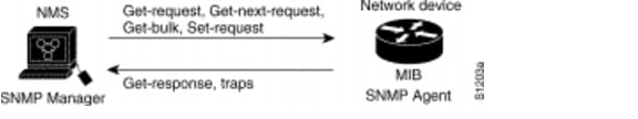
The SNMP manager uses information in the MIB to perform the operations described in Table 1-5.
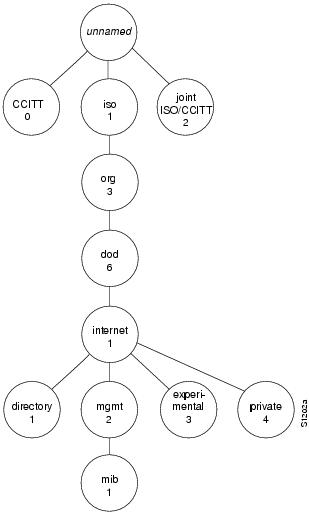
Internet MIB Hierarchy
The MIB structure is logically represented by a tree hierarchy (see Figure 1-4). The structure uses branches and the branches that fall below each category have short text strings and integers to identify them. Text strings describe object names, and integers allow computer software to create compact, encoded representations of the names. For example, the Cisco MIB variable authAddr is an object name and is denoted by number 5, which is listed at the end of its object identifier number 1.3.6.1.4.1.9.2.1.5.
The object identifier in the Internet MIB hierarchy is the sequence of numeric labels on the nodes along a path from the root to the object. The Internet standard MIB is represented by the object identifier 1.3.6.1.2.1. It also can be expressed as iso.org.dod.internet.mgmt.mib. (See Figure 1-4.)
Figure 1-4 Internet MIB Hierarchy
SNMP MIB
An SNMP MIB is an abstract database, that is, a conceptual specification for information that a management application may read and modify in a certain form. This does not imply that the information is kept in the managed system in that same form. The SNMP agent translates between the internal data structures and formats of the managed system and the external data structures and formats defined for the MIB.
The SNMP MIB is conceptually a tree structure with conceptual tables, described in more detail in the following sections. Relative to this tree structure, the term "MIB" is used in two ways. In one way, it is actually a MIB branch, usually containing information for a single aspect of technology, such as a transmission medium or a routing protocol. A MIB used in this way is more accurately called a MIB module, and is usually defined in a single document.
In the other way, a MIB is a collection of such branches. Such a collection of MIB branches might comprise, for example, all of the MIB modules implemented by a given agent, or the entire collection of MIB modules defined for SNMP.
MIBs can be standard or enterprise. Internet standard MIBs are defined by working groups of the IETF and published as RFCs. Enterprise MIBs are defined by other organizations, which are usually individual companies. Done properly, enterprise MIBs instrument technology not covered by standard MIBs, either completely or as an extension to a standard MIB.
The prototypical standard MIB is MIB-II, the second revision of the original SNMP MIB. MIB-II contains branches for the basic areas of instrumentation, such as the system, its network interfaces, IP, and TCP. All of these started out in a single MIB module, but as SNMPv2 evolves, they are being split into separate modules.
Compliance
Cisco MIBs are a set of variables that are private extensions to the Internet standard MIB-II. The MIB-II is documented in RFC 1213 (Management Information Base for Network Management of TCP/IP-based Internets: MIB-II). This RFC includes information on the benefits of the new feature, supported platforms, related documents, troubleshooting tips, configuration examples, and a detailed command reference.
Cisco Compliance
At present, Cisco implementations of standard MIBs are often read-only or have some objects or object groups missing because of security concerns or time requirements for implementation. Since Cisco IOS Release 10.2, developers must document such specifics with AGENT-CAPABILITIES from RFC 1904.
Implementation
To find what MIBs Cisco implements, start at ftp-eng.cisco.com with ftp://ftp-eng.cisco.com/pub/mibs/README.
This contains a list of MIBs available for various software versions. The MIB list cannot account for MIBs not included in a particular software subset or because a feature is turned off. Whether or not the MIB is included is the function of AGENT-CAPABILITIES descriptions and the snmpORTable (RFC 1907) in later software versions.
SNMP MIB Tables
Tables are a powerful and often confusing aspect of SNMP MIBs. Architectural purists say SNMP has conceptual tables, not real tables. This is because every object, whether in a table or not, is a leaf of the tree, identified by an object identifier (OID) that includes an instance. So, in an abstract sense, all objects are alike. But practically speaking, SNMP has tables, and using or implementing them gets somewhat more complex than implementing scalars, which are single object instances.
Tables have a rigid structure, defined in the SMI. Tables can contain only simple objects, not other tables, although multiple indexes can represent the concept of tables in tables. An entry, or row, in a table is uniquely identified by one or more table indexes, also called auxiliary objects. The OID of an object from a table is the OID for that object's position in the MIB tree concatenated with a representation of all the table indexes for an entry in the table.
For example, the Interface MIB (RFC 1573) has a key table called the ifTable. Its index object is ifIndex, an integer. Minus the instance, the OID for a counter from that table is:
iso.internet.mgmt.mib-2.interfaces.ifTable.ifEntry.ifInOctets
Or, numerically:
1.3.6.1.2.1.2.2.1.10
For the interface with ifIndex 7, the full OID is:
iso.internet.mgmt.mib-2.interfaces.ifTable.ifEntry.ifInOctets.7
1.3.6.1.2.1.2.2.1.10.7
Observe that row selection (instance) comes after column selection. This can be particularly confusing when you are applying the principle of lexical order to a table. Using the GetNext protocol operation to walk a table, you can proceed by column, that is, all instances for a column are returned before the next column is started.
Table indexes can be much more complex than tables. Here is an example from the Cisco VINES MIB. The INDEX clause from the ASN.1 definition is:
INDEX { cvForwNeighborHost,
ifIndex,
cvForwNeighborPhysAddress }
The first two indexes are simple integers, with ifIndex being imported from the standard ifTable. The final index is a variable length octet string. Including the integers is simple and obvious. The variable-length index object gets more complex. RFC 1212 includes rules for encoding variable length index objects as instances. The general rule is that the value is preceded by a length, and the length and each part of the value are separate subidentifiers.
So, for example, if we have neighbor host number 9, ifIndex 3, and an Ethernet neighbor physical address 0000.0c03.1ef0, the instance portion of an object for that row is 9.3.6.0.0.12.3.30.240.
In RFC 1902, SNMPv2 extends the instance encoding rules to include an "IMPLIED" keyword that can be used on the final instance object if it is variable length. When "IMPLIED" is present, the string instance cannot have a zero length in front of it.
Because lexical ordering for variable length instance objects effectively sorts them by length, your ASCII text index will not come out naturally in alphabetical order.
CISCO-SRST-MIB Object Groups
Table 1-6 lists the CISCO-SRST-MIB objects, which are presented according to their group.
The CISCO-SRST-MIB is organized by the following groups listed in Table 1-6
•![]() csrstConf
csrstConf
•![]() csrstNotifInfo
csrstNotifInfo
•![]() csrstActiveStats
csrstActiveStats
•![]() csrstSipConf
csrstSipConf
•![]() CiscoSrstMIBNotifs
CiscoSrstMIBNotifs
SRST Traps
SRST traps are SNMP traps, which are unsolicited notifications of an unusual or a catastrophic system event sent to the system administrator.
SRST traps or alerts are sent for the following:
•![]() Notification (alarm/trap): SRST SCCP port is down.
Notification (alarm/trap): SRST SCCP port is down.
•![]() Threshold (trap and event correlation) on phones registering back and forth between CM and SRST router due to flapping WAN link.
Threshold (trap and event correlation) on phones registering back and forth between CM and SRST router due to flapping WAN link.
•![]() Threshold (trap and event correlation) on phones registering back and forth between SIP server/proxy and SIP SRST router due to flapping WAN link.
Threshold (trap and event correlation) on phones registering back and forth between SIP server/proxy and SIP SRST router due to flapping WAN link.

Note ![]() Send traps by modem or ISDN dial backup links to a secondary NMS when the primary NMS is down. (Do this through the configuration in the SRST router.)
Send traps by modem or ISDN dial backup links to a secondary NMS when the primary NMS is down. (Do this through the configuration in the SRST router.)
Cisco-SRST-MIB Object Mappings
Table 1-7 lists the CISCO-SRST-MIB OID mappings.
Glossary
The following terms are used in this document.
ATA — Analog Telephone Adaptor
BRI — Basic Rate Interface
ccb — Call Control Block
CCME — Cisco CallManager Express
COR — Class of Restriction
CTI — Computer Telephony Integration
CUE — Cisco Unity Express
DN — directory number
DnD — do-not-disturb
E&M — ear and mouth (also recEive and transMit)
Ephone — Ethernet phone
FXO — foreign exchange office
GUI — Graphical User Interface
IETF — Internet Engineering Task Force
IVR — Interactive Voice Response
MIB — Management Information Base
MoH — Music on hold
MWI — message-waiting indicator
OID — Object Identifier
PLAR — private line, automatic ringdown
PRI — Primary Rate Interface
rcb — Registrar Control Block
RFC — Requests for Comment
SCCP — Skinny Client Control Protocol
SIP — Session Initiated Protocol
SNMP — Simple Network Management Protocol
SRST — Survivable Remote Site Telephony
TCL — Tool Command Language
VoFR — Voice over Frame Relay
 Feedback