Setting Up an HTTPS Network
Setting Up an HTTPS Network
This section describes the prerequisites for setting up an HTTPS network of Unity Connection servers, and provides a high-level task list of all of the tasks that you need to complete for the setup, and the order in which they should be completed. If you are unfamiliar with HTTPS networking concepts, you should first read the Overview of HTTPS Networking chapter and then review the task list and procedures before beginning the setup.
Prerequisites
Before starting the setup, verify that the following prerequisites have been met on each server that join the HTTPS network (for clusters, verify these prerequisites for the publisher server):
-
The server meets the requirements listed in the “Requirements for HTTPS Networking” section of the System Requirements for Cisco Unity Connection Release 15, available at https://www.cisco.com/c/en/us/td/docs/voice_ip_comm/connection/15/requirements/b_15cucsysreqs.html.
-
Unity Connection is already installed.
-
The servers networked together are directly accessible through TCP/IP port 25 (SMTP), or SMTP messages are routable through an SMTP smart host. In addition, both locations must be able to route to each other via HTTP on port 8081 or HTTPS on port 8444.
-
In order for directory synchronization and message exchange to occur between the two locations in a HTTPS network, the locations must have the following connectivity with each other:
-
HTTPS (if you choose to encrypt the connection) or HTTP connectivity, for directory synchronization.
-
SMTP connectivity, for voice message exchange.
-
-
For Unity Connection clusters, you must have a smart host available to resolve the SMTP domain of the cluster to both the publisher and subscriber servers in order for message traffic to reach the cluster subscriber server in the event that the publisher server is down.
In addition, before setting up an HTTPS network of Unity Connection servers, you should be familiar with the concepts in the “ Dial Plan” section of the “Call Management” chapter in the System Administration Guide for Cisco Unity Connection Release 15, available at https://www.cisco.com/c/en/us/td/docs/voice_ip_comm/connection/15/administration/guide/b_15cucsag.html.
Task List for Setting Up an HTTPS Network
Use this task list to set up an HTTPS network between Unity Connection servers or clusters. The cross-references take you to detailed procedures.
If you have a Unity Connection cluster, do the following tasks only on the publisher server.
-
Determine the network topology and the arrangement of the locations in the network depending upon the number of Cisco Unity Connection servers. See the “Deciding the Network Topology, page 2-4” section.
-
Make decisions about your networking deployment approach and gather information needed to configure the network. See the “Making Deployment Decisions and Gathering Needed Information for Setting Up an HTTPS Network, page 2-6 section.
-
Determine how messages are routed between the locations. See the “Determining SMTP Routing Between Locations, page 2-7” section.
-
Check the display name of each server that you are joining to the network, and modify it if it is not unique, or if you want to select a more descriptive name. Also check the SMTP domain of each server that you are joining to the network, and modify it if it is not unique. See the “Verifying Each Unity Connection Server has a Unique Display Name and SMTP Domain, page 2-7” section.

Caution
If the display name of a server matches the display name of another server in the network, the server cannot join the network. Similarly, if the SMTP domain matches the SMTP domain of another server in the network, the server cannot join the network.
-
Now start creating an HTTPS network by linking two Unity Connection servers together as per hub and spoke topology and top-down approach. See the “Linking Unity Connection Servers with HTTPS Link, page 2-9” section.
-
If any servers in the network require a smart host to transmit and receive SMTP messages from other servers (for example, because a firewall separates the servers, or because the servers are part of a Unity Connection cluster), configure the smart host, and configure the applicable locations to route through the host. See the “Configuring a Smart Host, page 2-11” section.

Note
For each Unity Connection cluster that you have added to the network, you must configure all other locations to route to the cluster through a smart host in order for message traffic to reach the cluster subscriber server in the event that the publisher server is down. (You also configure the smart host to resolve the SMTP domain of the cluster to both the publisher and subscriber servers.)
-
For each cluster that you have added to the network, add the IP address of the subscriber server to the IP address access list on every other location on the network. This ensures that the other locations can receive message traffic from the subscriber server if the publisher server is down. See the “Configuring SMTP Access for Cluster Subscriber Servers, page 2-12” section.
-
Verify that replication is complete among locations. See the “Checking Replication Status Within the Network, page 2-14” section.
-
Configure search spaces at each location to allow users that are homed at the location to address the users at other locations. See the “Configuring Search Spaces for HTTPS Network, page 2-15” section.
-
Secure the network so that message transmissions are not misdirected. See the “Securing the HTTPS Network, page 2-16” section.
-
Optionally, set up cross-server features. See the “Cross-Server Sign-In, Transfers, and Live Reply in HTTPS Networking ” chapter.
-
Test the network. See the “Testing the HTTPS Network Setup, page 2-16” section.
-
Optionally, set up a network-wide All Users distribution list. See the “Creating a Network-Wide All Voicemail Users Distribution List, page 2-18” section.
-
If you have not already done so, set up VPIM Networking to connect the Unity Connection locations to any other VPIM-compatible voice messaging systems. See the “VPIM Networking” chapter of the Networking Guide for Cisco Unity Connection Release 15, at https://www.cisco.com/c/en/us/td/docs/voice_ip_comm/connection/15/networking/guide/b_15cucnetx.html.
-
Optionally, create a mapping of which users are homed on which location. See the “Mapping Users to Home Locations, page 2-18” section.
Procedures for Setting Up an HTTPS Network
See the following sections:
Deciding the Network Topology
Before you start setting up a network, you need to create an HTTPS network map based on the following considerations:
-
Number of locations
-
Depth of the HTTPS network must be less than or equal to two
-
Configuration of the locations
-
Number of direct HTTPS links to any location must be less than or equal to five.
-
Number of homed subscribers on each server
In an HTTPS network, the Unity Connection locations are joined together as per hub and spoke topology. However, the number of hubs and spokes and the depth of the network depend upon the number of locations that we need to connect in the network. It is required to maintain the depth of an HTTPS network map to only second level. Following are the different types of recommended HTTPS network maps based on the number of Unity Connection locations:
-
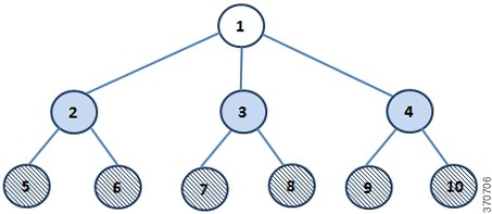
Network Map of 10 Unity Connection Locations
-
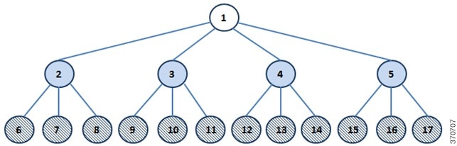
Network Map of 17 Unity Connection Locations
-
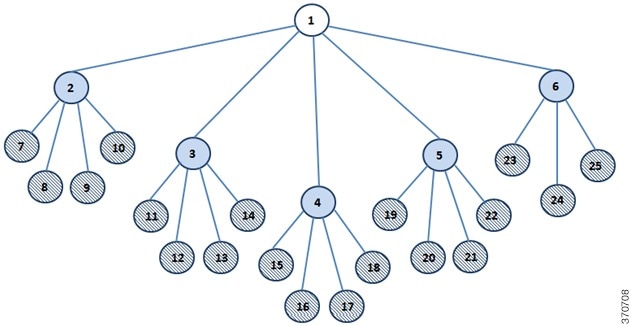
Network Map of 25 Unity Connection Locations
In the above network maps :
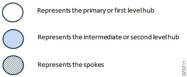
While deciding the number of hubs and spokes as per the network maps shown above, try to associate equal number of HTTPS links with every location (except spokes) in the network.
Now after deciding the number of hubs and spokes, you need to determine which location should act as hub and which location should act as spoke based on the configuration of the locations. First of all, arrange all the locations in the network in the descending order of their OVA size. Now the location that has the highest OVA should act as primary or first level hub. However, if the two or more locations have same OVAs then the location that has the least number of homed subscribers should act as primary or first level hub. Similarly, from the rest of the locations, the locations that have the highest OVA and least number of homed subscribers (if the OVA size of two or more locations is same) should act as intermediate or second level hub(s) depending upon the number of second level hubs, The remaining locations should act as spokes connected to the intermediate hubs.
For example, if you have 10 locations that need to be connected in an HTTPS network, then the recommended network map is shown in Figure 1, which decides the number of hubs and spokes in the network. It also decides the depth of the network as second level. As per the network map shown in Figure 1, for 10 locations, you need one primary hub, three intermediate hubs and six spokes. Now, you need to decide which location should act as hub and which location should act as spoke. To determine the hubs and spokes, arrange the locations in the descending order of their OVA size and increasing order of their homed subscribers (if the OVA size is same for two or more locations), as shown in Table 1:
|
Location Name |
OVA Size |
Number of Homed Subscribers |
|---|---|---|
|
1 |
7 vCPU |
10 K |
|
2 |
7 vCPU |
15 K |
|
3 |
4 vCPU |
8 K |
|
4 |
4 vCPU |
10 K |
|
5 |
4 vCPU |
10 K |
|
6 |
2 vCPU |
4 K |
|
7 |
2 vCPU |
5 K |
|
8 |
2 vCPU |
5 K |
|
9 |
2 vCPU |
5 K |
|
10 |
2 vCPU |
5 K |
As shown in Table 1, location 1 and location 2 has the highest and the same OVA size but the number of homed subscribers is less on location 1 as compared to location 2. Therefore, location 1 should act as primary hub. Now, from the rest of the locations, three locations should act as intermediate hub. The locations 2 and 3 have the highest OVA size and least number of the homed subscribers (if the OVA size is same). Therefore, locations 2 and 3 should act as intermediate hubs. For third intermediate location, you can treat either location 4 or location 5 as intermediate hub as both the locations have same configuration. The remaining locations, which are 5, 6, 7, 8, 9, and 10 act as spokes connected to the intermediate hubs.
In an HTTPS network, the directory synchronization between two locations occurs through the connecting hub(s) locations whereas the voice message exchange occurs point to point. For example, in the network topology of 10 locations shown above, if spoke 5 needs to synchronize directory information with spoke 6, it occurs through hub 2. However, if the spoke 5 needs to send voice message to spoke 6, it directly sends the message to spoke 6.
Directory Size Scaling
With the release of Cisco Unity Connection 14SU3 and later, the directory size limit for users has been increased to 160k in a network. Following is the recommended HTTPS network map based on the number of Unity Connection locations supporting 160k users:

In the above network map:
|
Location Name |
OVA Size |
Number of Homed Subscribers |
|---|---|---|
|
1 |
7 vCPU |
10 K |
|
2 |
7 vCPU |
10 K |
|
3 |
7 vCPU |
10 K |
|
4 |
7 vCPU |
20 K |
|
5 |
7 vCPU |
20 K |
|
6 |
7 vCPU |
20 K |
|
7 |
7 vCPU |
20 K |
|
8 |
7 vCPU |
20 K |
|
9 |
7 vCPU |
20 K |
|
10 |
7 vCPU |
10 K |
For more information on hub and spoke topology see the Overview of HTTPS Networking chapter.
Making Deployment Decisions and Gathering Needed Information for Setting Up an HTTPS Network
After creating the network map, be sure to plan for the following, and gather the applicable information:
-
If your network includes voice messaging servers that do not meet the prerequisites for joining a HTTPS network but support the Voice Profile for Internet Mail (VPIM) protocol (for example, Cisco Business Edition, Unity Connection 2.x servers, Cisco Unity 4.x and 5.x, or other VPIM-compatible systems), use VPIM Networking to connect them.
-
We recommend the following approaches:
-
Unless your servers are already configured for VPIM, set up rest of the network first, then set up VPIM Networking.
-
Select the Unity Connection locations in the network to handle the configuration of VPIM locations and contacts. These locations are referred to as the “VPIM bridgeheads.” The VPIM location and contact objects are replicated from the VPIM bridgeheads to all other Unity Connection locations in the HTTPS network so that the locations can address VPIM messages; the networked locations then forward the messages to the VPIM bridgehead for delivery to the remote voice messaging server.
Note
It is recommended that the location that has the minimum number of homed subscribers and highest OVA size should act as VPIM bridgehead.
-
If you are migrating a VPIM location to an HTTPS network (for example, because you used VPIM Networking to connect two or more Cisco Unity Connection 2.x servers and have upgraded the servers to Unity Connection 15) set up the HTTPS network first. After the directory is fully replicated and you have tested message exchange between the Unity Connection locations, remove the VPIM locations and VPIM contacts that represent the migrated servers and their users. The task list reminds you when to do this task. For more information on migration from Cisco Unity to Unity Connection, see the “Migrating from Cisco Unity 4.x and Later to Unity Connection 7.x and Later ” section of the “Maintaining Cisco Unity Connection Server” chapter of the Install, Upgrade, and Maintenance Guide for Cisco Unity Connection, Release 15, available at https://www.cisco.com/c/en/us/td/docs/voice_ip_comm/connection/15/install_upgrade/guide/b_15cuciumg.html.
-
-
By default, every Unity Connection location (server or cluster) includes several predefined system distribution lists, which you can modify but not delete. If you have not renamed these lists so that the list names are unique on each location, or if you have added additional lists whose names are identical across locations, during initial replication each location automatically adds the remote server name to the display name of any remote lists whose names overlap with local list names. (The default lists are All Voicemail Users, Undeliverable Messages, and All Voicemail-Enabled Contacts.) This can cause confusion when local users try to address to those remote lists.
-
To solve this problem, you can use one of the following approaches:
-
If you want to maintain separate lists on each location, you can modify the name of each list on its home location so that it is unique (for example "All Voicemail Users on <Location Name>") and notify your users of the new list names for each server. If you choose this approach, you should also modify the recorded name of each list to indicate its source.
-
Alternatively, after setting up the network, you can create a master list that includes all users on all networked locations. The task list includes instructions on when and how to do this task.
-
-
If you want to synchronize Unity Connection user data with user data in an LDAP directory, we recommend that you configure Unity Connection for integration with the LDAP directory prior to setting up the network, to simplify testing and troubleshooting.
-
Make note of the following information about each server that is joining the network:
-
The IP address or fully qualified domain name (FQDN) of the server.
-
The user name and password of a user account that is assigned to the System Administrator role.
-
The dial strings that other servers use to call this server, if cross-server sign-in or transfer are configured on other servers to hand off calls to this server.
-
Determining SMTP Routing Between Locations
In order for directory synchronization and message exchange to occur between the two locations in an HTTPS network, both the locations must have the following connectivity with each other:
-
HTTPS (if you choose to encrypt the connection) or HTTP connectivity, for directory synchronization.
-
SMTP connectivity, for voice message exchange.
In each direction, you can either route messages directly or use an SMTP smart host to route messages to the recipient. It is recommended to use an SMTP smart host in the following situations:
-
The locations are separated by a firewall that blocks SMTP transmissions.
-
Any of the locations is a Cisco Unity Connection cluster.
When a location is a cluster, you must configure the opposite location to route to the cluster through a smart host in order for message traffic to reach the cluster subscriber server in the event that the publisher server is down, and configure the smart host to resolve the SMTP domain of the cluster to the IP addresses of both the publisher and subscriber servers. In this case, we recommend that you route traffic in both directions through the smart host.
Verifying Each Unity Connection Server has a Unique Display Name and SMTP Domain
Each Unity Connection server that you join to an HTTPS network must have a unique display name. The display name must be unique both among Unity Connection locations and among VPIM locations. If the display name is not unique, the server cannot join the network. For new Unity Connection installations, the display name is typically the same as the host name of the server; however, if you changed the display name or upgraded the server from Unity Connection 2.x (which uses "Local VMS" as the default display name), you may need to change the display name so that it does not overlap with other locations on the network.
 Tip |
Choose a display name for each server that is descriptive and that helps you identify the location when it is listed among all locations in the organization in Cisco Unity Connection Administration. |
Each Unity Connection server that you join to the network must also have a unique SMTP domain, both among Unity Connection locations and among VPIM locations. By default, the SMTP domain is configured during installation to include the hostname of the server, in order to insure that it is unique. However, if the SMTP domains of multiple servers have been modified to the same value, you must change the domains to unique values before joining the servers in a network.
If you are migrating a server from VPIM Networking to HTTPS networking, it is likely that the display name or SMTP domain of the server overlaps with the VPIM location configured for the server. If the domain name overlaps, you need to disrupt messaging to the VPIM location while doing the migration-either by changing the SMTP domain of the VPIM location, or by removing the VPIM location.
Steps to Verify Each Cisco Unity Connection Server Has a Unique Display Name and SMTP Domain
Procedure
|
Step 1 |
Check the Display Name of the first server:
|
|
Step 2 |
Check the SMTP domain of the first server:
|
|
Step 3 |
Check the Display Name and SMTP Domain Name of all VPIM locations homed on the local server:
|
|
Step 4 |
Repeat Step 1 through Step 3 on each location joined to the network. |
|
Step 5 |
If the Display Name of a location conflicts with that of another location, or you want to modify a name to be more descriptive, change one of the display names: |
|
Step 6 |
Change the Display Name of the Unity Connection location:
|
|
Step 7 |
To change the Display Name of a VPIM location:
|
|
Step 8 |
If there are any remaining Display Name conflicts, repeat Step 5 as necessary to resolve each conflict. |
|
Step 9 |
If the SMTP domain of a server conflicts with that of another location, change one of the domain names: |
|
Step 10 |
To change the SMTP Domain of a Unity Connection location:
|
|
Step 11 |
To change the SMTP Domain Name of a VPIM location: |
|
Step 12 |
If there are any remaining SMTP domain conflicts, repeat Step 9 as necessary to resolve each conflict. |
Linking Unity Connection Servers with HTTPS Link
To create an HTTPS network of Unity Connection servers, you start by linking two servers together via an HTTPS link. At a single point of time, a particular location can be joined with only one location in the network. After joining one location to another, make sure that the directory synchronization is completed between the two locations before joining another location to the network. Each Unity Connection server becomes a location in the network. When a Unity Connection cluster is linked to a location, the cluster is also counted as one location in the network.
If you are setting up a new HTTPS network, you should follow the bottom-up approach for joining two Unity Connection locations in the network. In the bottom-up approach, you start by joining the spokes with their intermediate hubs and then the intermediate hubs with the primary hub. The main advantage of the bottom-up approach is that you can join multiple intermediate hubs with their spokes simultaneously. However, at a single point of time, a particular intermediate hub can make connection with one spoke only. Similarly, at a particular instance of time, the primary hub can join with only one intermediate hub. For example, if you need to create a network as per network map shown in Figure 2.1, you should start creating network by joining location 5 to location 2, location 7 to location 3, and location 9 to location 4 simultaneously.
Note |
It is not recommended to join two locations to the same location or hub simultaneously. For example, you should not join location 5 and 6 simultaneously to location 2. |
In the next step, you can start joining location 6 with location 2, location 8 with location3, and location 10 with location 4 simultaneously. After joining the spokes with their intermediate hubs, start joining the intermediate hubs with the primary hub one by one to complete the network.
Note |
|
Joining Two Cisco Unity Connection Servers
Procedure
|
Step 1 |
In Cisco Unity Connection Administration (on either server), expand Networking and select HTTPS Links.
|
||
|
Step 2 |
On the Search HTTPS Links page, select Add. |
||
|
Step 3 |
On the New HTTPS Link page, select Link to Cisco Unity Connection Remote Location. |
||
|
Step 4 |
In the Publisher field, enter the IP address or fully-qualified domain name (FQDN) or hostname of the Unity Connection server that you want to connect to create the network. |
||
|
Step 5 |
In the Username field, enter the user name of an administrator at the location specified in the Publisher field. The administrator user account must be assigned the System Administrator role. |
||
|
Step 6 |
In the Password field, enter the password for the administrator specified in the Username field. |
||
|
Step 7 |
For Transfer Protocol settings, enable the SSL to encrypt directory synchronization traffic between the different locations. |
||
|
Step 8 |
By default, two tasks that run on their own schedule for data and recorded name directory synchronization from the remote location are enabled immediately after you create the HTTPS link. To disable either type of directory synchronization until you manually edit and enable the applicable synchronization task, uncheck the Enable task to synchronize directory data after the join or Enable task to synchronize recorded names after the join check boxes. |
||
|
Step 9 |
Select Link. |
||
|
Step 10 |
Select OK to confirm and a success message pops up as “You have successfully linked to the location”.
|
Configuring a Smart Host
SMTP is used to transmit messages between Unity Connection locations in a network.
If any pair of locations in the network cannot transmit and receive SMTP messages directly (for example, because a firewall separates the servers), you must configure these locations to route these messages through an SMTP smart host.
In addition, for each Unity Connection cluster that you add to the network, you must configure all other network locations to route to the cluster through a smart host in order for message traffic to reach the cluster subscriber server in the event that the publisher server is down, and configure the smart host to resolve the SMTP domain of the cluster to the IP addresses of both the publisher and subscriber servers. For example, a network has a single smart host and the following three locations:
-
Server A, which is not a cluster member
-
Cluster 1, which is made up of Server B, a publisher, and Server C, a subscriber
-
Cluster 2, which is made up of Server D, a publisher, and Server E, a subscriber
In order to create an HTTPS network, you would join Server A, Server B and Server D together to form the network. Note the following:
-
On Server A, you would configure the Unity Connection locations for Server B (which represents cluster 1) and Server D (which represents cluster 2) to route through the smart host.
-
On Server B (the cluster 1 publisher), you would configure the Unity Connection location for Server D (which represents cluster 2) to route through the smart host.
-
On Server D (the cluster 2 publisher), you would configure the Unity Connection location for Server B (which represents cluster 1) to route through the smart host.
-
On the smart host, you would configure the SMTP domain name of cluster 1 to resolve to the IP addresses of both Server B and Server C (for example, using DNS MX records). You would also configure the SMTP domain name of cluster 2 to resolve to both Server D and Server E.
Do the following tasks for each server that requires routing to other locations through a smart host:
-
Configure the SMTP smart host to accept messages from the Unity Connection server. If your network includes Unity Connection clusters, also configure the smart host to resolve the SMTP domain of the cluster to the IP addresses of both the publisher and subscriber servers. See the documentation for the SMTP server application that you are using.
-
Configure the Unity Connection server to relay messages to the smart host. See the Configuring the Cisco Unity Connection Server to Relay Messages to a Smart Host procedure .
-
Configure the Unity Connection server to route messages to the other Unity Connection locations through the smart host. See the Configuring the Cisco Unity Connection Server to Route Inter-Location Messages through the Smart Host procedure.
Configuring the Cisco Unity Connection Server to Relay Messages to a Smart Host
Procedure
|
Step 1 |
In Cisco Unity Connection Administration, expand System Settings > SMTP Configuration, then select Smart Host. |
|
Step 2 |
In the Smart Host field, enter the IP address or fully qualified domain name of the SMTP smart host server. (Enter the fully qualified domain name of the server only if DNS is configured.) |
|
Step 3 |
Select Save. |
Configuring the Cisco Unity Connection Server to Route Inter-Location Messages through the Smart Host
Procedure
|
Step 1 |
In Cisco Unity Connection Administration, expand Networking, then select Locations. |
|
Step 2 |
Select the name of a location that requires routing through a smart host. |
|
Step 3 |
Check the Route to This Remote Location Through SMTP Smart Host check box. |
|
Step 4 |
Select Save. |
|
Step 5 |
Repeat Step 1 through Step 4 for each additional location that requires routing through the smart host. |
Configuring SMTP Access for Cluster Subscriber Servers
When you create an HTTPS network that includes a Unity Connection cluster server pair, you join only the publisher server of the pair to the network. In order for all locations in the network to communicate directly with the cluster subscriber server when the subscriber status is Primary, you must configure all network locations (except for the publisher server that is clustered with the subscriber server) to allow SMTP connections from the subscriber server.
Direct SMTP connectivity is needed so that locations can continue to receive user message traffic from the cluster while the publisher server does not have Primary status and the routing from the cluster to other locations is not done via a smart host. Direct SMTP connectivity with the subscriber server does not impact directory updates, because directory updates are only replicated from the publisher server.
For example, a network has the following three locations:
-
Server A, which is not a cluster member
-
Cluster 1, which is made up of Server B, a publisher, and Server C, a subscriber
-
Cluster 2, which is made up of Server D, a publisher, and Server E, a subscriber
In order to create an HTTPS network, you would join Server A, Server B and Server D together. For direct SMTP access, the following steps are required:
-
On Server A, you would need to add the IP addresses of both Server C and Server E (the two subscriber servers) to the IP address access list so that Server A can communicate with either subscriber server if it has Primary status.
-
On Server B (the cluster 1 publisher), you would add the IP address of Server E (the cluster 2 subscriber) to the IP address access list; and on Server D (the cluster 2 publisher), you would add the IP address of Server C (the cluster 1 subscriber) to the IP address access list.
Alternatively, you can configure each cluster location to route messages to every other location through a smart host; when you do this, the other Unity Connection locations do not need to accept SMTP connections directly from the cluster subscriber when it has Primary status, because the cluster subscriber establishes the SMTP connection with the smart host rather than directly with every other location. In the example above, the alternate configuration would entail the following:
-
On Server B (the cluster1 publisher), you would configure a smart host, and configure the Unity Connection locations for Server A and Server D (the cluster 2 publisher) to route through the smart host.
-
On Server D (the cluster 2 publisher), you would configure a smart host, and configure the Unity Connection locations for Server A and Server B (the cluster 1 publisher) to route through the smart host.
For instructions on configuring routing through a smart host, see the Configuring a Smart Host, page 2-11 section. Note that when more than one cluster is joined to a network, you should have already configured each cluster to route messages to other clusters through the smart host; in this case, all you need do in addition is to configure the cluster to route through the smart host to any servers that are not configured as clusters.
Configuring Direct SMTP Access for Cluster Subscriber Servers
Procedure
|
Step 1 |
On a network location, in Cisco Unity Connection Administration, expand System Settings > SMTP Configuration, then select Server. |
||
|
Step 2 |
On the Edit menu, select Search IP Address Access List. |
||
|
Step 3 |
Select Add New. |
||
|
Step 4 |
On the New IP Address page, enter the IP address of a cluster subscriber server at another location on the network.
|
||
|
Step 5 |
Select Save. |
||
|
Step 6 |
On the IP Address page, make sure that the Allow Connection check box is checked. |
||
|
Step 7 |
Select Save. |
||
|
Step 8 |
Repeat Step 2 through Step 7 for each additional subscriber server on the network (other than the subscriber server that is paired with the server you are configuring). |
||
|
Step 9 |
Checking Replication Status Within the Network
When initial replication begins among locations, it can take a few minutes to a few hours for data to be fully replicated between all locations, depending on the size of your directory.
On each location in the network, there are two tasks which control the schedule on which the Reader polls the remote Feeder for directory data and the schedule on which it polls for recorded names. By default, the tasks are enabled and run every 15 minutes. If you have unchecked the Enable Task to Synchronize Directory Data After the Join or Enable Task to Synchronize Recorded Names After the Join check boxes while linking the Unity Connection locations, you must configure the schedule and enable the tasks before synchronization can begin.
You can use the Edit HTTPS Link page and Task Schedule page in Cisco Unity Connection Administration interface to determine whether synchronization is progressing successfully or has completed. Do the following procedure to check synchronization status between locations and to configure schedules for the two synchronization tasks.
Tip |
On Unity Connection 15 locations, you can also use the Voice Network Map tool in Cisco Unity Connection Serviceability to check replication status. With the tool, you can quickly locate replication problems in a network, and get information about the status of replication between any two locations in the network. For more details, select Help > This Page from within the tool, or see the “Using the Voice Network Map Tool in HTTPS Networking” chapter of the Cisco Unified Serviceability Administration Guide Release 15 at https://www.cisco.com/c/en/us/td/docs/voice_ip_comm/connection/15/serv_administration/guide/b_15cucservag.html |
Checking the Status of Synchronization Between Cisco Unity Connection Locations And Configure Task Schedules
Procedure
|
Step 1 |
In Cisco Unity Connection Administration on a location, select Networking and HTTPS Links. |
|
Step 2 |
On the Search HTTPS Links page, select the Display Name of the HTTPS link. |
|
Step 3 |
On the Edit HTTPS Link page, check the values of the following fields:
|
|
Step 4 |
View the Synchronize Directory With Local Network task, and enable it or change the schedule, if necessary:
|
|
Step 5 |
From the Task Definition Basics page, select Task Definition > Task Definitions to go to the list of all tasks. |
|
Step 6 |
View the Synchronize Voice Names With Local Network task, and enable it or change the schedule, if necessary:
|
Configuring Search Spaces for HTTPS Network
When you initially set up a network between locations, users that are homed on one location are not able to address messages to users at other locations, because the users on each location are in separate partitions and use search spaces that do not contain the partitions of users on the other locations. After initial replication completes between the locations, you can reconfigure your search spaces to include partitions that are homed on other servers, and you can change the search scope of users, routing rules, call handlers, directory handlers, and VPIM locations to use a search space that is homed on a remote location. (Note that while both partitions and search spaces are replicated between locations, you cannot assign users or other objects to a partition that is homed on another location.)
Note |
When limit search users to search scope containing users of another location, no users are displayed. |
If you have not made any changes to the default partitions and search spaces on any server, at each location, you can add the default partition of each remote Cisco Unity Connection location to the search space that local users are using. For example, in a network of three servers named Server A, Server B, and Server C with no changes to the system defaults, in Cisco Unity Connection Administration on Server A you would add the “Server B Partition” and “Server C Partition” default partitions as members of the “Server A Search Space” default search space; in Unity Connection Administration on Server B you would add “Server A Partition” and “Server C Partition” to “Server B Search Space,” and so on.
For instructions on adding partitions to search spaces, see the “Dial Plan” section of the “Call Management” chapter in the System Administration Guide for Cisco Unity Connection Release 15, available at https://www.cisco.com/c/en/us/td/docs/voice_ip_comm/connection/15/administration/guide/b_15cucsag.html.
Securing the HTTPS Network
No user credentials are transmitted as part of HTTPS communications. However, in order to protect the security of SMTP addresses that are contained in the messages, make sure that any smart hosts that are involved in SMTP message transmission between Unity Connection locations are configured to route messages properly, as it may be possible to extract SMTP addresses from the messages. See the documentation for the SMTP server application that you are using for instructions.
Testing the HTTPS Network Setup
To test the HTTPS network configuration, create test user accounts or use existing user accounts on each Unity Connection location. When setting up user accounts in Cisco Unity Connection Administration to be used in the tests, be sure to do the following for each account:
-
Record a voice name.
-
Record and enable an internal greeting.
-
On the User Basics page, for Search Scope, select a search space that includes the partitions of remote users.
-
On the User Basics page, check the List in Directory check box.
-
On the Playback Message Settings page, check the Before Playing Each Message, Play the Sender's Information check box.
-
Optionally, if you plan to enable and test cross-server live reply, ensure that the account belongs to a class of service for which the Users Can Reply to Messages from Other Users by Calling Them check box is checked on the Edit Class of Service > Message Options page. (The check box is not checked by default.)
Verifying Messaging Between Users on Different Unity Connection Locations
Procedure
|
Step 1 |
Sign in to a Unity Connection location as a user. |
|
Step 2 |
Follow the prompts to record and send messages to users who are associated with other Unity Connection locations. |
|
Step 3 |
Sign in to the applicable Unity Connection location as the recipient user to verify that the message was received. |
|
Step 4 |
Repeat Step 1 through Step 3 on other Unity Connection locations. |
Verifying Call Transfers from the Automated Attendant to Users on Other Unity Connection Locations
Procedure
|
Step 1 |
From a non-user phone, call a Unity Connection location that has been configured to handle outside callers, and enter the extension of a user who is associated with another Unity Connection location. |
|
Step 2 |
Verify that you reach the correct user phone. |
Verifying Call Transfers from a Directory Handler to Users on Other Cisco Unity Connection Locations
Procedure
|
Step 1 |
From a non-user phone, call a Unity Connection location that has been configured to handle outside callers, and transfer to a directory handler. |
|
Step 2 |
Verify that you can find a user who is associated with another Unity Connection location in the phone directory, and that the directory handler transfers the call to the correct user phone. |
Verifying Identified User Messaging Between Networked Users (When Identified User Messaging Is Enabled)
Procedure
|
Step 1 |
Verify that Unity Connection plays an internal greeting for users who leave messages, by doing the following sub-steps:
|
|
Step 2 |
Verify that users are identified when the recipient listens to a message, by doing the following sub-steps:
|
Verifying Live Reply Between Users on Different Cisco Unity Connection Locations
Procedure
|
Step 1 |
From a user phone, call a user who is associated with another Unity Connection location, and allow the call to be forwarded to voicemail. |
|
Step 2 |
Leave a message. |
|
Step 3 |
Sign in to the applicable Unity Connection location as the recipient user and listen to the test message that you recorded in Step 2. |
|
Step 4 |
After listening to the message, verify that the user conversation allows you to live reply to the message by saying “Call sender” or using the applicable key presses for the user conversation type. (To find the key presses for a particular conversation, see the “Cisco Unity Connection Phone Menus and Voice Commands” chapter of the User Guide for the Cisco Unity Connection Phone Interface, Release 15, available at https://www.cisco.com/c/en/us/td/docs/voice_ip_comm/connection/15/user/guide/phone/b_15cucugphone.html). |
|
Step 5 |
Verify that the live reply call is correctly transferred to the phone of the user who left the message. |
Creating a Network-Wide All Voicemail Users Distribution List
If you would like to create a master distribution list that includes all users on all servers in the network, do the following tasks:
-
On each location in the network, rename the All Voicemail Users list with a unique name (for example All Voicemail Users on <Location Name>). For instructions, see the “Configuring System Distribution Lists” section in the “System Distribution Lists” chapter in the System Administration Guide for Cisco Unity Connection Release 15, available at https://www.cisco.com/c/en/us/td/docs/voice_ip_comm/connection/15/administration/guide/b_15cucsag.html.
-
Create a new All Voicemail Users system distribution list on one location to use as the master list.
-
Add the lists from all locations as members of the master list.
-
Put all lists except the master list in partitions that do not belong to a search space that users use, so that they cannot address to any list except the master. For example, on each location, create a new partition called Hidden DLs on <Location Name> and put the list homed at that location in that partition. (By default, new partitions are not a member of any search space.)
Tip |
To avoid having users generate large amounts of voice message traffic using reply-all to reply to messages sent to the master list, you should use search spaces to restrict access to the master list to a small subset of users. These users can use a search space that is essentially identical to the search space that other users use, except for the addition of the partition containing the master list. |
Mapping Users to Home Locations
Each server or cluster handles a distinct group of users. In large organizations, it is possible that more than one server or cluster is in use at the same physical location. In this case, you need to determine which user accounts to create on each of the servers (the "home" server or location for each user), and keep a record of the mapping. This record is needed for the following reasons:
-
User phones must forward calls to the system on which the users are homed.
-
If user phones have a “Messages” or a speed-dial button that dials the number to access voicemail, the buttons must be configured to call the system on which the users are homed.
-
If you do not configure cross-server sign-in, users must dial the pilot number of the server or cluster that they are associated with to check their messages; in this case, you need to tell the correct number to the users to dial when calling their home server.
To create a record of the mapping, run the Users report on each Uni ty Connection location. The information in this report includes the user name and primary location. For more information, see the “Reports” section of the “Advanced System Settings” chapter in the System Administration Guide for Cisco Unity Connection Release 15, available at https://www.cisco.com/c/en/us/td/docs/voice_ip_comm/connection/15/administration/guide/b_15cucsag.html.
Notable Behavior in Networked Unity Connection Servers
See the following sections:
Networked Broadcast Messages are Not Supported
Broadcast messages cannot be sent to multiple locations within a network.
Networked Dispatch Messages are Not Supported
Dispatch messaging is not supported across locations. Dispatch messages addressed to recipients at other locations within a network are delivered to remote users as regular messages. You should configure dispatch messaging only when the message recipient is a system distribution list that does not include users on other networked locations.
Manual Synchronization and Resynchronization Runs Both Directory and Voice Name Synchronization Tasks
The Sync and Resync All button on the Search HTTPS Links page starts the Synchronize Directory With Local Network task. When that task completes, it automatically starts the Synchronize Voice Names With Local Network task. These tasks normally run independently on separate schedules.
Adding Remote Users as Private Distribution List Members
When creating private lists, users can add members from other locations if allowed by their search scope, in which case the same set of users who are reachable when addressing a message or placing a call can also be added as members of a private list. Private lists are not replicated to other locations; when a user addresses a message to a private list, the home location of the user expands the distribution list and addresses messages to each individual recipient on the list.
Consider notifying users in the event that the following members are inadvertently removed from their lists:
-
When you delete a Unity Connection location, remote users at that location are removed from all private lists.
-
When a VPIM contact becomes a Unity Connection user, the contact is removed from all private lists.
 Feedback