Cisco BTS 10200 Softswitch ISDN Guide, Release 7.0
Bias-Free Language
The documentation set for this product strives to use bias-free language. For the purposes of this documentation set, bias-free is defined as language that does not imply discrimination based on age, disability, gender, racial identity, ethnic identity, sexual orientation, socioeconomic status, and intersectionality. Exceptions may be present in the documentation due to language that is hardcoded in the user interfaces of the product software, language used based on RFP documentation, or language that is used by a referenced third-party product. Learn more about how Cisco is using Inclusive Language.
- Updated:
- June 22, 2010
Chapter: Chapter 1 - ISDN Provisioning
- Introduction
- Description of Backhaul Set, Group, and Session
- Network Side PRI
- User Side PRI
- Cisco BTS 10200 Provisioning
- ISDN Profiles
- ISDN Features and Supplementary Services
- ISDN PRI PBX Variant Setup
- Intertel 256 with NI2
- Intertel 256 with DMS-100
- Intertel 256 with 4ESS
- Intertel 256 with 5ESS
- Lucent Definity G3r with NI2
- Lucent Definity G3r with DMS-100
- Lucent Definity G3r with 5ESS
- Nortel Northstar with NI2
- Nortel Option 11 with NI2
- Nortel Option 11 with DMS-100
- Siemens Hicom 300 with NI2
- Siemens Hicom 300 with DMS-100
- Siemens Hicom 300 with 4ESS
- Siemens Hicom 300 with 5ESS
- Toshiba Strada DK424 with NI2
ISDN Provisioning
Introduction
This chapter describes ISDN provisioning for the Cisco BTS 10200 Softswitch. It provides the procedures to operate, manage, and troubleshoot ISDN signaling on the Cisco BTS 10200 Softswitch and voice gateways.
For Stream Control Transmission Protocol (SCTP)/User Adaptation (IUA)ISDN Provisioning, the basic ISDN network elements and signaling connections are shown in . Standby elements in the figure are omitted for clarity.
Figure 1-1 ISDN Network Elements
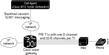

Note ![]() The Cisco BTS 10200 Softswitch Call Agent (CA) supports multiple voice gateways, or PBXs.
The Cisco BTS 10200 Softswitch Call Agent (CA) supports multiple voice gateways, or PBXs.
Description of Backhaul Set, Group, and Session
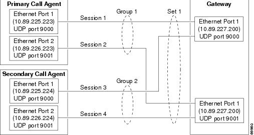
The backhaul session parameters used in provisioning are illustrated in . As shown in the figure, Call Agent Side A is connected to the media gateway (MGW) using the Group A signaling paths (Sessions A1 and A2), and is designated as primary. If one of these sessions goes down, the system uses the other session for signaling between Call Agent Side A and the MGW. There is no need for the Softswitch to switch over to Call Agent Side B. If the primary Call Agent goes down, then the Cisco BTS 10200 switches to the secondary Call Agent.
Figure 1-2 Backhaul Set, Group, and Session

Network Side PRI
The Network Side PRI feature allows the Cisco BTS 10200 Softswitch to communicate with PBXs. This feature provides support for the ISDN PRI Network Side basic call-control procedures as described in Q.931 ISDN Call Control Procedures. The network-side stack has the following PRI variants enabled:
•![]() ISDN US NI2 PRI (TR 1268)
ISDN US NI2 PRI (TR 1268)
•![]() ISDN Q931 PRI
ISDN Q931 PRI
•![]() ISDN DMS
ISDN DMS
•![]() ISDN ATT 4ESS PRI
ISDN ATT 4ESS PRI
•![]() ISDN ATT 5ESS PRI
ISDN ATT 5ESS PRI
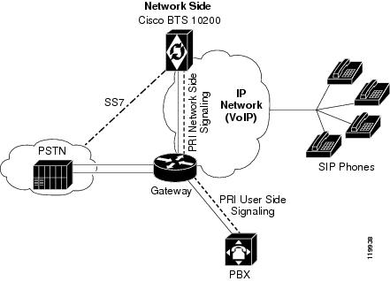
Figure 1-3 shows a sample PRI network-side configuration.
Figure 1-3 PRI Network-Side Configuration
User Side PRI
The User Side PRI feature allows provisioning when the Cisco BTS 10200 Softswitch does not support the SS7 variant of a particular country. This feature provides support for the ISDN PRI User Side basic call-control procedures as described in Q.931 ISDN Call Control Procedures. The user-side stack has the following PRI variants enabled:
•![]() ISDN US NI2 PRI (TR 1268)
ISDN US NI2 PRI (TR 1268)
•![]() ISDN Q931 PRI
ISDN Q931 PRI
•![]() ISDN DMS
ISDN DMS
•![]() ISDN ATT 4ESS PRI
ISDN ATT 4ESS PRI
•![]() ISDN ATT 5ESS PRI
ISDN ATT 5ESS PRI
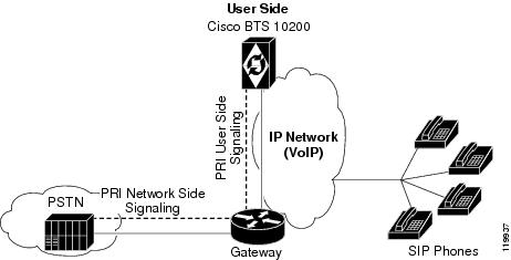
Figure 1-4 shows a sample PRI user-side configuration.
Figure 1-4 PRI User-Side Configuration
Cisco BTS 10200 Provisioning
This section provides an overview of the Cisco BTS 10200 Softswitch provisioning steps. The basic Cisco BTS 10200 provisioning sequence is outlined below.
Note ![]() These steps provision ISDN-specific data in the Cisco BTS 10200 Softswitch database. Referenced data tables, such as Dial Plan and Subscriber Profile must already be provisioned. Additional commands are also necessary to provision routing and translation for ISDN channels (see the Cisco BTS 10200 Softswitch CLI Database for more information).
These steps provision ISDN-specific data in the Cisco BTS 10200 Softswitch database. Referenced data tables, such as Dial Plan and Subscriber Profile must already be provisioned. Additional commands are also necessary to provision routing and translation for ISDN channels (see the Cisco BTS 10200 Softswitch CLI Database for more information).
Provisioning
This section provides the ISDN provisioning steps.
•![]() See the Cisco BTS 10200 Softswitch CLI Database for explanations of each token in the command.
See the Cisco BTS 10200 Softswitch CLI Database for explanations of each token in the command.
•![]() After entering each command, press the Return (Enter) key.
After entering each command, press the Return (Enter) key.
•![]() See the "ISDN Profiles" section for information regarding profiles.
See the "ISDN Profiles" section for information regarding profiles.
•![]() Performing steps 1, 2 and 3 provisions ISDN FAS for ISDN backhaul using RUDP.
Performing steps 1, 2 and 3 provisions ISDN FAS for ISDN backhaul using RUDP.
•![]() Performing steps 1, 2 and 4 provisions ISDN NFAS for ISDN backhaul using RUDP, which includes D channel backup.
Performing steps 1, 2 and 4 provisions ISDN NFAS for ISDN backhaul using RUDP, which includes D channel backup.
•![]() See the "International PRI Setup" section for information on provisioning for International PRI.
See the "International PRI Setup" section for information on provisioning for International PRI.
•![]() See the "ISDN PRI PBX Variant Setup" section for information on provisioning certain specific PBX variants.
See the "ISDN PRI PBX Variant Setup" section for information on provisioning certain specific PBX variants.
•![]() See Chapter 2 "Multiple Trunk Groups on a Single ISDN D Channel" for provisioning multiple trunk groups on a single D channel.
See Chapter 2 "Multiple Trunk Groups on a Single ISDN D Channel" for provisioning multiple trunk groups on a single D channel.
•![]() See Chapter 3 "ISDN Backhaul Support using IUA/SCTP" in Chapter 3 to provision ISDN backhaul for IUA/SCTP.
See Chapter 3 "ISDN Backhaul Support using IUA/SCTP" in Chapter 3 to provision ISDN backhaul for IUA/SCTP.
Note ![]() On a big, fast gateway (BFG), there is no concept of a slot number from a PRI backhaul perspective, although a BFG resides on a particular slot in the chassis. The architecture of a BFG is such that each slot acts as an independent gateway in itself. The Cisco BTS 10200 Softswitch addresses individual BFG cards by the card IP address—so the slot number is zero. Current CLI implementation uses a total of 16 bits with the D channel slot represented by 8 bits and the D channel port represented by 8 bits. To interface with a BFG, set the slot to 0 when the port is greater than 255 (8 bits).
On a big, fast gateway (BFG), there is no concept of a slot number from a PRI backhaul perspective, although a BFG resides on a particular slot in the chassis. The architecture of a BFG is such that each slot acts as an independent gateway in itself. The Cisco BTS 10200 Softswitch addresses individual BFG cards by the card IP address—so the slot number is zero. Current CLI implementation uses a total of 16 bits with the D channel slot represented by 8 bits and the D channel port represented by 8 bits. To interface with a BFG, set the slot to 0 when the port is greater than 255 (8 bits).
Note ![]() The proprietary-supp token must be set to 8 bits when provisioning NI2.
The proprietary-supp token must be set to 8 bits when provisioning NI2.
The following steps provide the commands and examples for ISDN provisioning:
Step 1 ![]() Log on to the active EMS by entering the following commands on a console that can communicate by IP with the active EMS.
Log on to the active EMS by entering the following commands on a console that can communicate by IP with the active EMS.
Note ![]() To verify which EMS is currently active, log on to any EMS or CA/Feature Server (FS) machine as a root user, and enter the command nodestat. This displays the IP address of the active EMS. Then exit.
To verify which EMS is currently active, log on to any EMS or CA/Feature Server (FS) machine as a root user, and enter the command nodestat. This displays the IP address of the active EMS. Then exit.
a. ![]() Open a UNIX shell or XTerm window (or, in Windows, choose Start > Run > Command prompt).
Open a UNIX shell or XTerm window (or, in Windows, choose Start > Run > Command prompt).
b. ![]() At the UNIX shell prompt, enter ssh and the IP address or domain name of the active EMS.
At the UNIX shell prompt, enter ssh and the IP address or domain name of the active EMS.
ssh -l <CLI username> ip address
c. ![]() At the password prompt, enter the password for the CLI username.
At the password prompt, enter the password for the CLI username.
<password for CLI username>
The system responds with a prompt.
Step 2 ![]() Add the MGW and backhaul set. Refer to Figure 1-5 for a sample configuration for backhaul session connections between a CA and a gateway.
Add the MGW and backhaul set. Refer to Figure 1-5 for a sample configuration for backhaul session connections between a CA and a gateway.
a. ![]() Add the MGW profile for the voice gateway. Multiple MGW profiles can be created for different media gateways per your configuration requirements.
Add the MGW profile for the voice gateway. Multiple MGW profiles can be created for different media gateways per your configuration requirements.
add mgw-profile id=mgwprofile2; vendor=Cisco; packet-type=IP; mgcp-variant=NONE;
rbk-on-conn-supp=n; isdn=y; mgcp-erqnt-supp=n; mgcp-hairpin-supp=n;
mgcp-cmd-seq-supp=n; mgcp-version=MGCP_1_0;
b. ![]() Add the MGW using the MGW profile created in Step 2a.
Add the MGW using the MGW profile created in Step 2a.
add mgw ID=mgw-isdn; tsap-addr=10.89.227.200; call-agent-id=CA146;
mgw-profile-id=mgwprofile2; type=TGW;
c. ![]() Add the backhaul session set ID for the gateway using the MGW ID specified in Step 2b with the appropriate values for your system.
Add the backhaul session set ID for the gateway using the MGW ID specified in Step 2b with the appropriate values for your system.
add backhaul-set SET-ID=backset1; MGW-ID=mgw-isdn; SET-NAME=set1;
d. ![]() Add the Reliable User Datagram Protocol (RUDP) backhaul sessions for the gateway using the backhaul session set ID created in Step 2c and appropriate values configured on the gateway:
Add the Reliable User Datagram Protocol (RUDP) backhaul sessions for the gateway using the backhaul session set ID created in Step 2c and appropriate values configured on the gateway:
Information as seen on IOS Gateway
session group group1 10.89.225.223 9000 10.89.227.200 9000 0
session group group1 10.89.226.223 9001 10.89.227.200 9001 0
session group group2 10.89.225.224 9000 10.89.227.200 9000 0
session group group2 10.89.226.224 9001 10.89.227.200 9001 0
CLI associated with information seen on gateway:
add rudp-backhaul-session set-id=backset1; session-name=session1; group-name=group1; call-agent-tsap-addr=10.89.225.223;
call-agent-backhaul-port=9000;mgw-tsap-addr=10.89.227.200; mgw- backhaul-port=9000;
add rudp-backhaul-session set-id=backset1; session-name=session2; group-name=group1;
call-agent-tsap-addr=10.89.226.223; call-agent-backhaul-port=9001;
mgw-tsap-addr=10.89.227.200; mgw-backhaul-port=9001;
add rudp-backhaul-session set-id=backset1; session-name=session3; group-name=group2;
call-agent-tsap-addr=10.89.225.224; call-agent-backhaul-port=9000;
mgw-tsap-addr=10.89.227.200; mgw-backhaul-port=9000;
add rudp-backhaul-session set-id=backset1; session-name=session4; group-name=group2;
call-agent-tsap-addr=10.89.226.224; call-agent-backhaul-port=9001;
mgw-tsap-addr=10.89.227.200; mgw-backhaul-port=9001;
Note ![]() The call-agent-tsap-addr token must be a physical IP address.
The call-agent-tsap-addr token must be a physical IP address.
Figure 1-5 Sample Configuration for Backhaul Session Connections Between a CA and a Gateway
Step 3 ![]() Configure PRI FAS. Figure 1-6 shows a sample configuration for Facility Associated Signaling (FAS).
Configure PRI FAS. Figure 1-6 shows a sample configuration for Facility Associated Signaling (FAS).
Note ![]() To configure PRI NFAS, go to Step 4.
To configure PRI NFAS, go to Step 4.
Figure 1-6 Sample Configuration for FAS

a. ![]() Add an ISDN D channel profile with the nfas-supp token set to N.
Add an ISDN D channel profile with the nfas-supp token set to N.
add isdn-dchan-profile id=NI2; description=dallas isdn dchan profile no.1;
type=swv-us-ni2-pri; interface-type=network; isdn-restart-pri-supp=y;
isdn-restart-interface-supp=y;isdn-service-supp=n; isdn-restart-chan-supp=y;
isdn-farend-init=n;isdn-query-supp=n;nfas-supp=n; bchan-neg-supp=y; t-301=300;
t-302=10; t-303=4; t-305=30;t-308=4; t-309=90;t-310=10; t-316=30; t-321=20;t-322=4;
t-323=30;
Note ![]() See the "ISDN Profiles" section for more information.
See the "ISDN Profiles" section for more information.
b. ![]() Add the ISDN interfaces.
Add the ISDN interfaces.
add isdn-intf isdn-dchan-id=100; intf=0;
c. ![]() Add the ISDN D channels using the backhaul session set ID added in Step 2c and ISDN interfaces added in Step 3b (where dchan-port refers to the DS1 span number used).
Add the ISDN D channels using the backhaul session set ID added in Step 2c and ISDN interfaces added in Step 3b (where dchan-port refers to the DS1 span number used).
add isdn-dchan id=100; backhaul-type=RUDP;SET-ID=backset1; dchan-slot=0;
dchan-port=1; dchan-type=primary; dchan-intf=0;isdn-dchan-profile-id=NI2;
d. ![]() Add an ISDN trunk group profile.
Add an ISDN trunk group profile.
add isdn-tg-profile id=dallas1; chrg-num-supp=Y;
e. ![]() Add the ISDN trunk groups using the ISDN trunk group profile added in Step 3d.
Add the ISDN trunk groups using the ISDN trunk group profile added in Step 3d.
add trunk-grp id=100;call-agent-id=CA146;tg-type=ISDN;tg-profile-id=dallas1;
pop-id=1;glare=all;mgcp-pkg-type=T; dial-plan-id=dp1; isdn-dchan-id=100;
Note ![]() For ISDN trunk groups, the mgcp-pkg-type token must be set to T.
For ISDN trunk groups, the mgcp-pkg-type token must be set to T.
f. ![]() Add the ISDN terminations using the MGW ID added in Step 2b.
Add the ISDN terminations using the MGW ID added in Step 2b.
add termination prefix=S4/DS1-1/; port-start=1; port-end=23; type=trunk;
mgw-id=mgw-isdn;
g. ![]() Add the ISDN trunks using the trunk group profile added in Step 3d, the ISDN interface added in Step 3b, the MGW ID added in Step 2b, and the ISDN termination used in Step 3f.
Add the ISDN trunks using the trunk group profile added in Step 3d, the ISDN interface added in Step 3b, the MGW ID added in Step 2b, and the ISDN termination used in Step 3f.
add trunk cic-start=1; cic-end=23; tgn-id=100; mgw-id=mgw-isdn;
termination-prefix=S4/DS1-1/; termination-port-start=1;termination-port-end=23;intf=0;
h. ![]() Add the subscriber, then link to the trunk group. See the Cisco BTS 10200 Softswitch Provisioning Guide for additional details. In the following example, the subscriber profile ID must already exist:
Add the subscriber, then link to the trunk group. See the Cisco BTS 10200 Softswitch Provisioning Guide for additional details. In the following example, the subscriber profile ID must already exist:
add subscriber id=pbx1@cisco.com; category=pbx; name=pbx1; status=active;
address1=1651 n glenville;address2=Richardson tx 75081; ss-number=643-77-1837;
billing-dn=972-233-9000; dn1=972-233-9000; ring-type-dn1=1;tgn-id=100;
sub-profile-id=dp1; term-type=none;
change trunk-grp id=100; main-sub-id=pbx1@cisco.com;
i. ![]() Go to the "Place MGW, ISDN D Channels, Trunk Groups, and Trunks In Service" section.
Go to the "Place MGW, ISDN D Channels, Trunk Groups, and Trunks In Service" section.
Step 4 ![]() Configure PRI NFAS. Figure 1-7 shows a sample configuration for NFAS.
Configure PRI NFAS. Figure 1-7 shows a sample configuration for NFAS.
Note ![]() To perform an ISDN D channel switchover, refer the Cisco BTS 10200 Softswitch CLI Database for additional information.
To perform an ISDN D channel switchover, refer the Cisco BTS 10200 Softswitch CLI Database for additional information.
This step also creates and provisions a backup ISDN D channel.
Figure 1-7 Sample Configuration for NFAS

a. ![]() Add the ISDN D channel profile with the nfas-supp token set to Y.
Add the ISDN D channel profile with the nfas-supp token set to Y.
add isdn-dchan-profile id=NI2; description=dallas isdn dchan profile no.1;
type=swv-us-ni2-pri; interface-type=network; isdn-restart-pri-supp=y;
isdn-restart-interface-supp=y;isdn-service-supp=n; isdn-restart-chan-supp=y;
isdn-farend-init=n;isdn-query-supp=n;nfas-supp=y; bchan-neg-supp=y; t-301=300;
t-302=10; t-303=4; t-305=30;t-308=4; t-309=90;t-310=10; t-316=30; t-321=20;t-322=4;
t-323=30;
b. ![]() Add the ISDN interfaces.
Add the ISDN interfaces.
add isdn-intf isdn-dchan-id=100; intf=0;
add isdn-intf isdn-dchan-id=100; intf=1;
add isdn-intf isdn-dchan-id=100; intf=2;
c. ![]() Add the primary and backup ISDN D channels using the session set ID added in Step 2c and the ISDN interfaces added in Step 4b.
Add the primary and backup ISDN D channels using the session set ID added in Step 2c and the ISDN interfaces added in Step 4b.
add isdn-dchan id=100; backhaul-type=RUDP; set-id=backset1; dchan-slot=0;
dchan-port=0; dchan-type=primary; dchan-intf=0; isdn-dchan-profile-id=NI2;
add isdn-dchan id=100; backhaul-type=RUDP; set-id=backset1; dchan-slot=0;
dchan-port=1; dchan-type=backup; dchan-intf=1; isdn-dchan-profile-id=NI2;
d. ![]() Add an ISDN trunk group profile.
Add an ISDN trunk group profile.
add isdn-tg-profile id=dallas1; chrg-num-supp=Y;
e. ![]() Add the ISDN trunk groups using the ISDN trunk group profile added in Step 4d.
Add the ISDN trunk groups using the ISDN trunk group profile added in Step 4d.
add trunk-grp id=100;call-agent-id=CA146; tg-type=ISDN; tg-profile-id=ISDN;
pop-id=1;glare=ALL;mgcp-pkg-type=T; dial-plan-id=dp1;isdn-dchan-id=100;
f. ![]() Add the ISDN terminations using the MGW added in Step 2b.
Add the ISDN terminations using the MGW added in Step 2b.
add termination prefix=s0/ds1-0/; port-start=1; port-end=23; type=trunk;
mgw-id=mgw_isdn;
add termination prefix=s0/ds1-1/; port-start=1; port-end=23; type=trunk;
mgw-id=mgw_isdn;
add termination prefix=s0/ds1-2/; port-start=1; port-end=24; type=trunk;
mgw-id=mgw-isdn;
g. ![]() Add the ISDN trunks using the trunk group ID added in Step 4e, the ISDN interfaces added in Step 4b, the MGW added in Step 2b, and the termination prefix added in Step 4f.
Add the ISDN trunks using the trunk group ID added in Step 4e, the ISDN interfaces added in Step 4b, the MGW added in Step 2b, and the termination prefix added in Step 4f.
add trunk cic-start=1; cic-end=23; tgn-id=100; mgw-id=mgw-isdn;
termination-prefix=s0/ds1-0/; termination-port-start=1;
termination-port-end=23;intf=0;
add trunk cic-start=24; cic-end=46; tgn-id=100; mgw-id=mgw-isdn;
termination-prefix=s0/ds1-1/; termination-port-start=1;
termination-port-end=23;intf=1;
add trunk cic-start=47; cic-end=70; tgn-id=100; mgw-id=mgw-isdn;
termination-prefix=s0/ds1-2/; termination-port-start=1;
termination-port-end=24;intf=2;
h. ![]() Add the subscriber, and then link the subscriber to the trunk group.
Add the subscriber, and then link the subscriber to the trunk group.
add subscriber id=pbx1@cisco.com; category=pbx; name=pbx1; status=active;
address1=1651 n glenville suite 200; address2=Richardson tx 75081;
ss-number=643-77-1837; billing-dn=972-233-9000; dn1=972-233-9000;
ring-type-dn1=1;tgn-id=100; sub-profile-id=dp1;
change trunk-grp id=100; main-sub-id=pbx1@cisco.com;
Place MGW, ISDN D Channels, Trunk Groups, and Trunks In Service
This procedure places the MGW and the ISDN trunk groups in service. This does not automatically place the trunk terminations in service. The trunk terminations must be equipped and placed in service separately.
Step 1 ![]() Place the MGW in service.
Place the MGW in service.
control mgw id=mgw-isdn; target-state=INS; mode=forced;
Step 2 ![]() Place the ISDN D channel in service.
Place the ISDN D channel in service.
control isdn-dchan id=100; dchan-type=PRIMARY; target_state=ins;
Step 3 ![]() Place the ISDN trunk group in service.
Place the ISDN trunk group in service.
control trunk-grp id=100; mode=forced; target_state=ins;
Step 4 ![]() Equip the trunk-terminations.
Equip the trunk-terminations.
equip trunk-termination tgn-id=100; cic=all;
Step 5 ![]() Place the trunk-terminations in service.
Place the trunk-terminations in service.
control trunk-termination tgn-id=100; mode=forced; target-state=ins; cic=all;
Verify Status of ISDN Services
This procedure verifies that the MGW, MGW terminations, trunks, ISDN D channels and trunk groups are in service. When the system reports that both the administrative and operational states are in service, it means that ISDN signaling is enabled in the network served by this Cisco BTS 10200 Softswitch. If the system reports any administrative or operational states as out of service (OOS), or not functioning, follow the specified troubleshooting instructions in the "Obtaining Documentation and Submitting a Service Request" section to correct the problem.
Note ![]() For a description of all administrative and operational states reported by the status command, see the Cisco BTS 10200 Softswitch Operations and Maintenance Guide, Release 7.0.
For a description of all administrative and operational states reported by the status command, see the Cisco BTS 10200 Softswitch Operations and Maintenance Guide, Release 7.0.
Verify MGW Status
Perform the following steps to verify the MGW status:
Step 1 ![]() Check the MGW status.
Check the MGW status.
>status mgw ID=mgw-isdn
MGW_ID -> mgw-isdn
RESULT -> ADM configure result in success
REASON -> ADM executed successfully
ADMIN_STATE -> ADMIN_INS
OPER_STATE -> Media gateway in working status
ISDN_BACKHAUL_STATUS -> SG is in service, RUDP backhaul session is up
AGGR_ID -> NULL
CACHED_IP_ADDRESS1 -> 10.89.227.117
CACHED_IP_ADDRESS2 -> 0.0.0.0
CACHED_IP_ADDRESS3 -> 0.0.0.0
CACHED_IP_ADDRESS4 -> 0.0.0.0
Step 2 ![]() If the administrative state is ADMIN_INS and the operational state is working status and the CA-to-MGW connection is functioning properly then ISDN backhaul status shows as "SG is in service, RUDP backhaul session is up". Proceed to the "Verify D Channel Status" section.
If the administrative state is ADMIN_INS and the operational state is working status and the CA-to-MGW connection is functioning properly then ISDN backhaul status shows as "SG is in service, RUDP backhaul session is up". Proceed to the "Verify D Channel Status" section.
Otherwise, stop and perform troubleshooting in accordance with the "Obtaining Documentation and Submitting a Service Request" section.
Verify D Channel Status
Perform the following steps to verify the D channel status:
Step 1 ![]() Verify the D channel status.
Verify the D channel status.
status isdn-dchan id=100; dchan-type=PRIMARY;
Step 2 ![]() If the administrative state is ADMIN_INS and the operational state is in-service, then signaling is functioning properly on this D channel. Proceed to the "Verify Trunk Group Status" section.
If the administrative state is ADMIN_INS and the operational state is in-service, then signaling is functioning properly on this D channel. Proceed to the "Verify Trunk Group Status" section.
Otherwise, stop and perform troubleshooting in accordance with the "Obtaining Documentation and Submitting a Service Request" section.
Verify Trunk Group Status
Perform the following steps to verify the trunk group status:
Step 1 ![]() Verify the trunk group status.
Verify the trunk group status.
status trunk-grp id=100;
Step 2 ![]() If the administrative state is ADMIN_INS and the operational state is in-service, signaling is functioning properly on this trunk group. Proceed to the "Verify Trunk Termination and Trunk Status" section.
If the administrative state is ADMIN_INS and the operational state is in-service, signaling is functioning properly on this trunk group. Proceed to the "Verify Trunk Termination and Trunk Status" section.
Otherwise, stop and perform troubleshooting in accordance with the "Obtaining Documentation and Submitting a Service Request" section.
Verify Trunk Termination and Trunk Status
Perform the following steps to verify the trunk termination and trunk status:
Step 1 ![]() Verify the trunk termination and trunk status. The following command queries both the trunk termination status and trunk (channel) status:
Verify the trunk termination and trunk status. The following command queries both the trunk termination status and trunk (channel) status:
status trunk-termination tgn-id=100; cic=8;
Reply : Success:
RESULT -> ADM configure result in success
REASON -> ADM executed successful
TGN ID -> 100
CIC -> 8
TERM ADMIN STATE -> ADMIN_INS
TERM OPER STATE -> Termination is idle
TERM REASON -> No fault reason available
TRUNK STATIC STATE -> ACTV
TRUNK DYNAMIC STATE -> TRNS
TRUNK REASON -> NON_FAULTY
The command in the following example queries trunk termination status and trunk status for channels 1 to 4:
status trunk-termination tgn-id=100; cic=1-4;
Reply : Success: Entries 1-4 of 4 returned.
TGN_ID -> 100
CIC -> 4
RESULT -> ADM configure result in success
REASON -> ADM executed successful
TERM_ADMIN_STATE -> ADMIN_INS
TERM_OPER_STATE -> Termination is idle
TERM_REASON -> No fault reason available
TRUNK_STATIC_STATE -> ACTV
TRUNK_DYNAMIC_STATE -> IDLE
TRUNK_REASON -> NON_FAULTY
TGN_ID -> 100
CIC -> 3
RESULT -> ADM configure result in success
REASON -> ADM executed successful
TERM_ADMIN_STATE -> ADMIN_INS
TERM_OPER_STATE -> Termination is idle
TERM_REASON -> No fault reason available
TRUNK_STATIC_STATE -> ACTV
TRUNK_DYNAMIC_STATE -> IDLE
TRUNK_REASON -> NON_FAULTY
TGN_ID -> 100
CIC -> 2
RESULT -> ADM configure result in success
REASON -> ADM executed successful
TERM_ADMIN_STATE -> ADMIN_INS
TERM_OPER_STATE -> Termination is idle
TERM_REASON -> No fault reason available
TRUNK_STATIC_STATE -> ACTV
TRUNK_DYNAMIC_STATE -> IDLE
TRUNK_REASON -> NON_FAULTY
TGN_ID -> 100
CIC -> 1
RESULT -> ADM configure result in success
REASON -> ADM executed successful
TERM_ADMIN_STATE -> ADMIN_INS
TERM_OPER_STATE -> Termination is idle
TERM_REASON -> No fault reason available
TRUNK_STATIC_STATE -> ACTV
TRUNK_DYNAMIC_STATE -> IDLE
TRUNK_REASON -> NON_FAULTY
Step 2 ![]() The system is functioning properly if all of the following conditions are shown in the system response:
The system is functioning properly if all of the following conditions are shown in the system response:
•![]() TERM_ADMIN_STATUS is ADMIN_INS
TERM_ADMIN_STATUS is ADMIN_INS
•![]() TERM_OPER_STATUS is TERMINATION IS IDLE
TERM_OPER_STATUS is TERMINATION IS IDLE
•![]() TERM_REASON is No fault reason available
TERM_REASON is No fault reason available
•![]() TRUNK_STATIC_STATE is ACTV
TRUNK_STATIC_STATE is ACTV
•![]() TRUNK_DYNAMIC_STATE is IDLE
TRUNK_DYNAMIC_STATE is IDLE
•![]() TRUNK_REASON is NON_FAULTY
TRUNK_REASON is NON_FAULTY
If all of these conditions are shown in the system response, you have completed this procedure.
Otherwise, perform troubleshooting in accordance with the "Obtaining Documentation and Submitting a Service Request" section.
International PRI Setup
This section describes how to provision the Cisco BTS 10200 Softswitch for International PRI. International PRI uses the International Telecommunications Union (ITU)/European Telecommunication Standards Institute (ETSI) standard.
Note ![]() ITU/ETSI uses a primary net-5 switch.
ITU/ETSI uses a primary net-5 switch.
Step 1 ![]() Configure PRI FAS.
Configure PRI FAS.
shows a sample configuration for Facility Associated Signaling (FAS).
Figure 1-8 Sample Configuration for FAS

a. ![]() Add ISDN D channel profile with the nfas-supp token set to N.
Add ISDN D channel profile with the nfas-supp token set to N.
add isdn-dchan-profile ID=NI2; description=dallas isdn dchan profile no.1;
type=SWV-ETSI-PRI; interface-type=network; isdn-restart-pri-supp=Y;
isdn-restart-interface-supp=y;isdn-service-supp=n; isdn-restart-chan-supp=y;
isdn-farend-init=n;isdn-query-supp=n;nfas-supp=n; bchan-neg-supp=y; t-301=300;
t-302=10; t-303=4; t-305=30;t-308=4; t-309=90;t-310=10; t-316=30; t-321=20;t-322=4;
t-323=30;
Note ![]() See the "ISDN Profiles" section for more information.
See the "ISDN Profiles" section for more information.
b. ![]() Add the ISDN interfaces.
Add the ISDN interfaces.
add isdn-intf isdn-dchan-id=100; INTF=0;
c. ![]() Add the ISDN D channels using the backhaul session set ID added in Step 2c in the "Provisioning" section and the ISDN interfaces added in Step 1b.
Add the ISDN D channels using the backhaul session set ID added in Step 2c in the "Provisioning" section and the ISDN interfaces added in Step 1b.
add isdn-dchan id=100; backhaul-type=RUDP;set-id=backset1; DCHAN-SLOT=0;
DCHAN-PORT=1; DCHAN-TYPE=primary; DCHAN-INTF=0; isdn-dchan-profile-id=NI2;
d. ![]() Add an ISDN trunk group profile.
Add an ISDN trunk group profile.
add isdn-tg-profile id=dallas1; chrg-num-supp=Y;
e. ![]() Add the ISDN trunk groups using the ISDN trunk group profile added in Step 1d.
Add the ISDN trunk groups using the ISDN trunk group profile added in Step 1d.
add trunk-grp id=100; call-agent-id=CA146;tg-type=ISDN; tg-profile-id=ISDN1;
glare=all; mgcp-pkg-type=T; dial-plan-id=dp1; dial-plan-id=dp1; isdn-dchan-id=100;
Note ![]() For ISDN trunk groups, the mgcp-pkg-type token must be set to T.
For ISDN trunk groups, the mgcp-pkg-type token must be set to T.
f. ![]() Add ISDN terminations using the MGW-ID added in Step 2b in the "Provisioning" section.
Add ISDN terminations using the MGW-ID added in Step 2b in the "Provisioning" section.
add termination PREFIX=S4/DS1-1/; PORT-START=1; PORT-END=15; TYPE=trunk;
MMGW-ID=mgw-isdn;
add termination PREFIX=S4/DS1-1/; PORT-START=17; PORT-END=32; TYPE=trunk;
MGW-ID=mgw-isdn;
Note ![]() Port 16 is reserved as the D channel. Do not add a termination and trunk for port 16.
Port 16 is reserved as the D channel. Do not add a termination and trunk for port 16.
g. ![]() Add the ISDN trunks using the tgn-id added in Step 1e, the isdn-intf added in Step 1b, the termination-prefix used in Step 1f, and the mgw-id added in Step 2b in the "Provisioning" section.
Add the ISDN trunks using the tgn-id added in Step 1e, the isdn-intf added in Step 1b, the termination-prefix used in Step 1f, and the mgw-id added in Step 2b in the "Provisioning" section.
add trunk CIC-START=1; CIC-END=15; TGN-ID=100; MGW-ID=mgw-isdn;
TERMINATION-PREFIX=S4/DS1-1/; TERMINATION-PORT-START=1;TERMINATION-PORT-END=15;INTF=0;
add trunk CIC-START=17; CIC-END=32; TGN-ID=100; MGW-ID=mgw-isdn;
TERMINATION-PREFIX=S4/DS1-1/;
TERMINATION-PORT-START=17;TERMINATION-PORT-END=32;INTF=0;
h. ![]() Add the subscriber, and then link to the trunk group.
Add the subscriber, and then link to the trunk group.
add subscriber id=<subscriber ID>; category=pbx; name=<name for PBX>; status=active;
address1=<street address>; address2=<city, state, zip code>; ssnumber=<Social Security
number of main subscriber, if available>; sip-url=//<gateway domain name>;
billing-dn=<phone number to be billed>; dn1=<phone number of main subscriber>;
ring-type-dn1=<audible ringing type>;tgn-id=<TG ID number>; sub-profile-id=<ID of
subscriber-profile table for this subscriber>;
i. ![]() Link to the trunk group.
Link to the trunk group.
change trunk-grp id=<TG ID number>; main-sub-id=<ID of main subscriber in subscriber
table>;
ISDN Profiles
This section describes the supported ISDN profiles.
Maintenance Message Support
This section describes the ISDN D channel profile parameters, which hold information about the ISDN D channels. These parameters are used to configure the Call Agent to interact with various types of PBXs having different configurations (for example, FAS), initialization procedures (Service or Restart), supporting different call-control or maintenance timer values, and so forth.
Consider the following definitions and meanings when:
•![]() The Call Agent can send restart messages to a PBX during trunk group initialization (restoral). The restart message can be any of the following:
The Call Agent can send restart messages to a PBX during trunk group initialization (restoral). The restart message can be any of the following:
–![]() One for all interfaces (all B channels on all T1 interfaces)
One for all interfaces (all B channels on all T1 interfaces)
–![]() One for each interface (all B channels on a specified T1 interface)
One for each interface (all B channels on a specified T1 interface)
–![]() A separate restart message for individual (indicated) B channels
A separate restart message for individual (indicated) B channels
•![]() The PBX can support sending service messages to the Call Agent.
The PBX can support sending service messages to the Call Agent.
–![]() Support by the PBX means the PBX takes action on service messages from the Call Agent and sends an acknowledgment message back to the Call Agent.
Support by the PBX means the PBX takes action on service messages from the Call Agent and sends an acknowledgment message back to the Call Agent.
–![]() Nonsupport by the PBX means the PBX does not send an acknowledgment message back to the Call Agent.
Nonsupport by the PBX means the PBX does not send an acknowledgment message back to the Call Agent.
•![]() The Maintenance message support the use of service and the restart messages handles the protocol discriminator for national coding (0x43). Unsolicited service acknowledgment messages are also handled, including proper update of the trunk or channel states.
The Maintenance message support the use of service and the restart messages handles the protocol discriminator for national coding (0x43). Unsolicited service acknowledgment messages are also handled, including proper update of the trunk or channel states.
The ISDN D channel profile is provisioned by use of the CLI. See the Cisco BTS 10200 Softswitch CLI Database for additional information. The following tokens configure the Call Agent to communicate properly with the PBX:
•![]() ISDN-RESTART-PRI-SUPP
ISDN-RESTART-PRI-SUPP
–![]() If YES—The CA sends a restart message for all interfaces (Restart Class 7).
If YES—The CA sends a restart message for all interfaces (Restart Class 7).
–![]() If NO—The PBX does not support a restart message for all interfaces (Restart Class 7). The CA does not send a "Restart All Interfaces" message.
If NO—The PBX does not support a restart message for all interfaces (Restart Class 7). The CA does not send a "Restart All Interfaces" message.
•![]() ISDN-RESTART-INTERFACE-SUPP
ISDN-RESTART-INTERFACE-SUPP
–![]() If YES—The PBX supports a restart message for single interface (Restart Class 6). The CA sends a single restart message for an individual interface.
If YES—The PBX supports a restart message for single interface (Restart Class 6). The CA sends a single restart message for an individual interface.
–![]() If NO—The PBX does not support a restart message for a single interface (Restart Class 6).
If NO—The PBX does not support a restart message for a single interface (Restart Class 6).
•![]() ISDN-SERVICE-SUPP
ISDN-SERVICE-SUPP
–![]() If NO—The PBX does not support service messages (B-channel availability). The CA sends a single service message for an individual channel.
If NO—The PBX does not support service messages (B-channel availability). The CA sends a single service message for an individual channel.
–![]() If YES—The PBX supports service messages (B-channel availability).
If YES—The PBX supports service messages (B-channel availability).
•![]() ISDN-RESTART-CHAN-SUPP
ISDN-RESTART-CHAN-SUPP
–![]() If YES—The CA sends single restart messages for individual channels (Restart Class 0).
If YES—The CA sends single restart messages for individual channels (Restart Class 0).
–![]() If NO—The CA does not send single restart messages for individual channels (Restart Class 0).
If NO—The CA does not send single restart messages for individual channels (Restart Class 0).
•![]() ISDN-FAREND-INIT—Allows PBX to bring far end in-service.
ISDN-FAREND-INIT—Allows PBX to bring far end in-service.
–![]() If YES—The CA sets B channels to Remote Block (RBLK) and waits for the remote PBX to send restart and service messages.
If YES—The CA sets B channels to Remote Block (RBLK) and waits for the remote PBX to send restart and service messages.
–![]() If NO—The CA performs an initialization or restoral procedure (sends RESTART or SERVICE messages)
If NO—The CA performs an initialization or restoral procedure (sends RESTART or SERVICE messages)
•![]() ISDN-QUERY-SUPP—Allows the CA to send ISDN status enquiry message to audit active calls.
ISDN-QUERY-SUPP—Allows the CA to send ISDN status enquiry message to audit active calls.
–![]() If YES—The PBX supports status enquiry messages.
If YES—The PBX supports status enquiry messages.
–![]() If NO—The PBX does not support status enquiry messages.
If NO—The PBX does not support status enquiry messages.
Note ![]() This value must be set correctly; otherwise, all calls will be lost during switchover.
This value must be set correctly; otherwise, all calls will be lost during switchover.
The following cases show situations where the tokens listed above are used:
---------------------------------------------------------------------------------------
Case 1: CA sends RESTART All Interface (Restart Class 7), a single restart for all interfaces in a PRI group.
ISDN-RESTART-PRI-SUPP=YES
---------------------------------------------------------------------------------------
Case 2: CA sends RESTART Single Interface (Restart Class 6), a single restart for each interface in the PRI group.
ISDN-RESTART-PRI-SUPP=NO
ISDN-RESTART-INTERFACE-SUPP=YES
---------------------------------------------------------------------------------------
Case 3: CA sends a SERVICE Message for each B channel in each interface of the PRI group.
ISDN-RESTART-PRI-SUPP=NO
ISDN-RESTART-INTERFACE-SUPP=NO
ISDN-SERVICE-SUPP=YES
---------------------------------------------------------------------------------------
Case 4: CA sends RESTART Single Channel (Restart Class 0), a single restart for each B-channel in each interface of the PRI group.
ISDN-RESTART-PRI-SUPP=NO
ISDN-RESTART-INTERFACE-SUPP=NO
ISDN-SERVICE-SUPP=NO
ISDN-RESTART-CHAN-SUPP=YES
---------------------------------------------------------------------------------------
Case 5: CA does not send any message and the remote side is responsible for initialization.
ISDN-RESTART-PRI-SUPP=NO
ISDN-RESTART-INTERFACE-SUPP=NO
ISDN-SERVICE-SUPP=NO
ISDN-RESTART-CHAN-SUPP=NO
ISDN-FAREND-INIT=YES
---------------------------------------------------------------------------------------
Case 6: CA does not send any message and no initialization is required for either side.
ISDN-RESTART-PRI-SUPP=NO
ISDN-RESTART-INTERFACE-SUPP=NO
ISDN-SERVICE-SUPP=NO
ISDN-RESTART-CHAN-SUPP=NO
ISDN-FAREND-INIT=NO
---------------------------------------------------------------------------------------
Customizing Trunk Group Profiles
To turn up a BTS 10200 trunk group with a new ISDN trunk group profile, you need to know the capabilities supported by the specific PBX at the remote site. The best way to determine these PBX capabilities is to review the appropriate version (model, software release, and patch number) of the PBX vendor documentation. If that documentation is unavailable or insufficient, the following BTS 10200 procedure is intended to help you determine some of the capabilities of the PBX as you customize the trunk group profile. However, the procedure might not provide you with all of the settings you need, or might not result in the correct values for all settings. Therefore, we strongly recommend that you use the PBX vendor documentation as your primary source of information about the PBX device when possible.
Perform the following steps on the BTS 10200 to customize the trunk group profile.
Step 1 ![]() Determine whether PBX supports the service message:
Determine whether PBX supports the service message:
a. ![]() Set the following tokens in the isdn-dchan-profile:
Set the following tokens in the isdn-dchan-profile:
isdn-service-supp=y;
isdn-restart-chan-supp=n;
isdn-restart-interface-supp=n;
isdn-farend-init=n;
isdn-restart-pri-supp=n;
b. ![]() Control the D channel out of service, then back in service.
Control the D channel out of service, then back in service.
c. ![]() Check the status of the trunk terminations within 30 seconds of restoring the D channel group.
Check the status of the trunk terminations within 30 seconds of restoring the D channel group.
–![]() If the operational state for the trunks is TRANS, the service message is not supported by the PBX (set isdn-service-supp=n;).
If the operational state for the trunks is TRANS, the service message is not supported by the PBX (set isdn-service-supp=n;).
–![]() If the operational state is IDLE, the service message is supported by the PBX (set isdn-service-supp=y;).
If the operational state is IDLE, the service message is supported by the PBX (set isdn-service-supp=y;).
Step 2 ![]() Determine whether PBX supports the restart message for a particular bearer channel:
Determine whether PBX supports the restart message for a particular bearer channel:
a. ![]() Set the following tokens in the isdn-dchan-profile:
Set the following tokens in the isdn-dchan-profile:
isdn-service-supp=<specify Y/N depending on whether service is supported>;
isdn-restart-chan-supp=y;
isdn-restart-interface-supp=n;
isdn-farend-init=n;
isdn-restart-pri-supp=n;
b. ![]() Control the D channel out of service, then back in service.
Control the D channel out of service, then back in service.
c. ![]() Check the status of the trunk terminations.
Check the status of the trunk terminations.
–![]() If the operational state for the trunks is TRANS, the restart channel message is not supported by the PBX (set isdn-restart-chan-supp=n;).
If the operational state for the trunks is TRANS, the restart channel message is not supported by the PBX (set isdn-restart-chan-supp=n;).
–![]() If the operational state is IDLE, then the restart channel message is supported by the PBX (set isdn-restart-chan-supp=y;).
If the operational state is IDLE, then the restart channel message is supported by the PBX (set isdn-restart-chan-supp=y;).
Step 3 ![]() Determine whether the PBX supports restart for the whole interface:
Determine whether the PBX supports restart for the whole interface:
a. ![]() Set the following tokens in the isdn-dchan-profile:
Set the following tokens in the isdn-dchan-profile:
isdn-service-supp=whatever;
isdn-restart-chan-supp=whatever;
isdn-restart-interface-supp=y;
isdn-farend-init=n;
isdn-restart-pri-supp=n;
b. ![]() Control the D channel out of service, then back in service.
Control the D channel out of service, then back in service.
c. ![]() Check the status of the trunk terminations.
Check the status of the trunk terminations.
–![]() If the operational state for terminations is TRANS, the restart interface message is not supported by the PBX (set isdn-restart-interface-supp=n;).
If the operational state for terminations is TRANS, the restart interface message is not supported by the PBX (set isdn-restart-interface-supp=n;).
–![]() If the operational state is IDLE, the restart interface message is supported by the PBX (set isdn-restart-interface-supp=y;).
If the operational state is IDLE, the restart interface message is supported by the PBX (set isdn-restart-interface-supp=y;).
Step 4 ![]() Determine whether the PBX supports the query message. The ISDN-QUERY-SUPP flag in the isdn-tg-profile indicates whether the PBX supports the ISDN query message.
Determine whether the PBX supports the query message. The ISDN-QUERY-SUPP flag in the isdn-tg-profile indicates whether the PBX supports the ISDN query message.
•![]() If this flag is NO (default), the query message is not supported by the PBX.
If this flag is NO (default), the query message is not supported by the PBX.
•![]() If this flag is YES, the query message is supported by the PBX.
If this flag is YES, the query message is supported by the PBX.
•![]() If you do not know the answer to whether the PBX supports the query message, then set ISDN-QUERY-SUPP=N;.
If you do not know the answer to whether the PBX supports the query message, then set ISDN-QUERY-SUPP=N;.
See the "Obtaining Documentation and Submitting a Service Request" section for more troubleshooting information.
ISDN Timer Configuration Parameters
The timer default values for the command-line interface (CLI) are set to default values required by the network side. There are minor differences in the timer values of user-side timer versus network-side timers, and these can be fine-tuned in accordance with user requirements. Table 1-1 compares the timer values of network-side and user-side state machines as specified in Q.931 and as implemented in the Cisco BTS 10200 Softswitch.
ISDN Features and Supplementary Services
ISDN features and supplementary services include the following:
•![]() Calling and Connected Name Delivery
Calling and Connected Name Delivery
•![]() Calling Number Identification Service (CNIP/CNIR)
Calling Number Identification Service (CNIP/CNIR)
•![]() Redirecting Number IE Support
Redirecting Number IE Support
Information Digit Feature
The Information Digit feature provides the functionality to receive and deliver originating line information (OLI or II digits) collected from an originating switch (or provisioned in the Cisco BTS 10200 Softswitch for local subscribers) to the far-end. The Nortel DMS variant of the ISDN PRI protocol supports using the Generic Digits Information element (Type of Digit = 4) to carry information such as Info Digits.
If Info Digits (Type of Digits = 4) are received from an incoming ISDN trunk group, these digits are considered as OLI and are used for policy-based routing. The OLI information can also be used for digit manipulation.
The processing of Generic Digits is controlled by use of the configurable GENDIGITS-IE-SUPP flag in the ISDN D Channel Profile table for an incoming trunk group. If this is configured as N, the Cisco BTS 10200 Softswitch ignores and drops the Generic Digits parameter in the SETUP message.
If GENDIGIT-IE-SUPP is configured as Y, the Cisco BTS 10200 Softswitch decodes and processes the Generic Digits IE from any code set is received.
Note ![]() The GENDIGITS-IE-CODESET flag in the ISDN D Channel Profile table is not applicable to the receiving trunk group.
The GENDIGITS-IE-CODESET flag in the ISDN D Channel Profile table is not applicable to the receiving trunk group.
The following new ISDN D Channel Profile table tokens are used to provision Generic Digits:
•![]() gendigit-ie-supp
gendigit-ie-supp
•![]() gendigit-ie-codeset
gendigit-ie-codeset
•![]() gendigit-tod-infodigit
gendigit-tod-infodigit
The following example shows how to provision new generic digit tokens:
add isdn-dchan-profile id=dms-250; type=swv-dms-pri; interface-type=network;
gendigit-ie-supp=y; gendigit-ie-codeset=6; gendigit-tod-infodigit=4;
Because the Info Digits information is associated with a charge number, whether the information is sent out as Info Digits depends on following factors:
•![]() If the send-bdn-as-cpn or send-bdn-for-emg token is set to Y for the main subscriber entry configured for an incoming trunk group (which can be CAS, ISDN, H323 or SIP), the Cisco BTS 10200 Softswitch sends the OLI configured in the incoming Subscriber table entry as Info Digits.
If the send-bdn-as-cpn or send-bdn-for-emg token is set to Y for the main subscriber entry configured for an incoming trunk group (which can be CAS, ISDN, H323 or SIP), the Cisco BTS 10200 Softswitch sends the OLI configured in the incoming Subscriber table entry as Info Digits.
•![]() If the billing-dn token is configured for a main subscriber entry for an incoming trunk group (which can be CAS, ISDN, H323 or SIP), the Cisco BTS 10200 Softswitch sends the OLI configured in the incoming Subscriber table entry as Info Digits.
If the billing-dn token is configured for a main subscriber entry for an incoming trunk group (which can be CAS, ISDN, H323 or SIP), the Cisco BTS 10200 Softswitch sends the OLI configured in the incoming Subscriber table entry as Info Digits.
•![]() If the OLI is available in a new call message from an incoming trunk group (which can be received as Generic Digits in ISDN or OLI in SS7), the Cisco BTS 10200 Softswitch passes the OLI received in the incoming message to the outgoing SETUP message.
If the OLI is available in a new call message from an incoming trunk group (which can be received as Generic Digits in ISDN or OLI in SS7), the Cisco BTS 10200 Softswitch passes the OLI received in the incoming message to the outgoing SETUP message.
•![]() If the main Subscriber entry is configured for the incoming trunk group, the Cisco BTS 10200 Softswitch sends the OLI configured in the incoming Subscriber table as Info Digits.
If the main Subscriber entry is configured for the incoming trunk group, the Cisco BTS 10200 Softswitch sends the OLI configured in the incoming Subscriber table as Info Digits.
•![]() If none of the configurations in the above bullets occurred, the Cisco BTS 10200 Softswitch does not send any Info Digits.
If none of the configurations in the above bullets occurred, the Cisco BTS 10200 Softswitch does not send any Info Digits.
If the gendigits-ie-supp token in an outgoing ISDN D Channel Profile is configured as Y and the gendigit-tod-infodigit token is nonzero, the Cisco BTS 10200 Softswitch sends a setup message with OLI in the Generic Digits IE (type of digits=GENDIGIT-TOD-INFODIGIT configured in the outgoing ISDN D Channel Profile).
If the gendigits-ie-supp token is configured as N in the outgoing ISDN D Channel Profile, or if the gendigits-tod-infodigits token is configured as 0 in the outgoing ISDN D Channel Profile, no Generic Digits IE is sent out.
The encoding of Generic Digits is always IA5. If a single I (single-digit Info Digit) is received in an incoming trunk group, the Cisco BTS 10200 Softswitch pads it with 0 and encodes it as II.
The code set in which a Generic Digits IE is sent is controlled by the gendigits-ie-codeset token in an outgoing ISDN D Channel Profile.
Calling and Connected Name Delivery
Calling Name (CNAME) delivery is a supplementary service that allows identification of a calling, or connected, name for PRI interfaces. The service allows calls flowing through a Cisco BTS 10200 Softswitch ISDN virtual gateway to pass the calling, or connected, name data between the ISDN adapter and the internal signaling adapter interface (SAI) to the basic call module (BCM). The service is configured in the ISDN D Channel Profile table. Table 1-2 describes the variants, messages, and IEs used for transporting a calling name IE.
Calling Number Identification Service (CNIP/CNIR)
The Calling Number Identification Presentation (CNIP) and Calling Number Identification Restriction (CNIR) services provide for:
•![]() Delivering a redirecting number to and from a PRI interface
Delivering a redirecting number to and from a PRI interface
•![]() Populating a PRI calling number with the original provisionable Signaling System 7 (SS7) calling party number (CPN), or the charge number (CN), if available
Populating a PRI calling number with the original provisionable Signaling System 7 (SS7) calling party number (CPN), or the charge number (CN), if available
•![]() Transferring a connected number received in a connect message end-to-end on a PRI-to-PRI call
Transferring a connected number received in a connect message end-to-end on a PRI-to-PRI call
Redirecting Number IE Support
Redirecting Number IE support is available for NI2/4ESS and 5ESS switch types, and allows passing a redirecting number IE from one call leg to another. DMS Original Called Party Number support is also available. This allows the Cisco BTS 10200 Softswitch to receive an original called party number (OCPN) from an incoming PRI (configured as DMS-100), and to send an OCPN to a PRI (configured as DMS-100) interface.
ISDN PRI PBX Variant Setup
The ISDN PRI implementation enhances the Cisco BTS 10200 Softswitch by allowing interconnection to small and medium businesses using legacy PBX PRI interfaces. The design provides for the transport of additional PRI Information Elements (IEs) and two messages. The IEs include high layer compatibility (HLC), low layer compatibility (LLC), redirecting number (RGN), original called number (OCN), and Connected Number (CN). Message support is also provided for NOTIFY messages, and supplementary service support is provided for the Calling Name feature.
The Cisco BTS 10200 Softswitch supports the following PRI variants:
•![]() Nortel DMS-100
Nortel DMS-100
•![]() Lucent-5ESS
Lucent-5ESS
•![]() AT&T-4ESS
AT&T-4ESS
•![]() NI2
NI2
Note ![]() The proprietary-supp token must be set to 8 bits when provisioning NI2.
The proprietary-supp token must be set to 8 bits when provisioning NI2.
The following sections provide the provisioning steps for specific PBXs. The steps are executed by using the Cisco BTS 10200 Softswitch CLI. For more information about using the CLI, see the Cisco BTS 10200 Softswitch CLI Database.
Table 1-3 lists the switch vendors, protocol, the section, and the page of the configuration example.
|
|
|
|
|
|
Lucent |
Unknown |
|||
Nortel |
Unknown |
Unknown |
||
Intertel |
||||
Siemens |
||||
Toshiba |
Unknown |
Unknown |
Unknown |
Use the ISDN provisioning steps provided in the "Cisco BTS 10200 Provisioning" section to provision the following PBXs, with the exception of Step 3a in the "Provisioning" section. Replace Step 3a, adding an ISDN D Channel profile, using the examples shown below for each PBX. You may need to modify the example given to suit your specific equipment setup.
Note ![]() We recommend configuring a DN1 on the main subscriber of each ISDN trunk for the CNAM feature. Otherwise, number delivery may not work as expected.
We recommend configuring a DN1 on the main subscriber of each ISDN trunk for the CNAM feature. Otherwise, number delivery may not work as expected.
Intertel 256 with NI2
To provision an Intertel 256 with NI2 (Intertel NI2 PBX), replace Step 3a with the following:
add isdn-dchan-profile id=intertel-cnamraw;type=swv-us-ni2-pri;isdn-service-supp=n;
isdn-restart-pri-supp=n;isdn-query-supp=y; isdn-restart-chan-supp=n;
isdn-restart-interface-supp=y; nfas-supp=n;bchan-neg-supp=y;
cname-encode-method=raw-disp; disp-ie-supp=y; disp-ie-codeset=0; isdn-farend-init=y;
send-group-dn=n;
Intertel 256 with DMS-100
To provision an Intertel 256 with DMS-100 (Intertel DMS-100 PBX), replace Step 3a with the following:
add isdn-dchan-profile id=intertel-dms100;type=swv-dms-pri;interface-type=network;
isdn-service-supp=y; isdn-restart-chan-supp=y; isdn-restart-interface-supp=y;
isdn-farend-init=n; send-group-dn=n;t-301=300;t-302=10;t-303=4;t-305=30; t-308=4;
t-309=90;t-310=10;t-316=30;t-322=4; t-323=30; isdn-query-supp=y;
isdn-restart-pri-supp=y;nfas-supp=n;t-321=20;bchan-neg-supp=y;iw-spec=t1-609;
disp-ie-supp=y;facil-ie-supp=n;cname-encode-method=protocol;
Intertel 256 with 4ESS
To provision an Intertel 256 with 4ESS (Intertel 4ESS PBX) with calling name support in a raw display IE, replace Step 3a with the following:
add isdn-dchan-profile id=intertel-4ess;type=swv-4ess;isdn-service-supp=n;
isdn-restart-pri-supp=n;isdn-query-supp=y; isdn-restart-chan-supp=n;
isdn-restart-interface-supp=y; nfas-supp=n;bchan-neg-supp=y;cname-encode-method=raw-disp;
disp-ie-supp=y; disp-ie-codeset=0; isdn-farend-init=y;facil-ie-supp=n; facil-ie-codeset=0;
flip-chan-ext-bit=n;
Intertel 256 with 5ESS
To provision an Intertel 256 with 5ESS (Intertel 5ESS PBX), replace Step 3a with the following:
add isdn-dchan-profile id=intertel-5ess; type=swv-5ess-pri; isdn-service-supp=n;
isdn-farend-init=n; isdn-restart-pri-supp=n;isdn-query-supp=y; nfas-supp=n;
isdn-restart-chan-supp=n; bchan-neg-supp=y;disp-ie-supp=y;
disp-ie-codeset=0; cname-encode-method=raw-disp
Lucent Definity G3r with NI2
To provision a Lucent Definity G3r with NI2 (FAS NI2 Lucent PBX) without service messaging, replace Step 3a with the following:
add isdn-dchan-profile id=lucent-fas; type=swv-us-ni2-pri;isdn-service-supp=n;
isdn-farend-init=y; isdn-restart-pri-supp=n; isdn-query-supp=y; nfas-supp=n;
isdn-restart-chan-supp=n; isdn-restart-interface-supp=y; bchan-neg-supp=y;
Note ![]() This configuration does not support CNAME.
This configuration does not support CNAME.
To provision an NI2 Lucent PBX with calling name support (per GR1367), and replacement of a calling party number with a charge number, replace Step 3a with the following two commands:
add isdn-dchan-profile id=lucent-ni2; type=swv-us-ni2-pri;isdn-service-supp=n;
isdn-farend-init=y; isdn-restart-pri-supp=n; isdn-query-supp=y;
nfas-supp=n;isdn-restart-chan-supp=n; isdn-restart-interface-supp=y;bchan-neg-supp=y;
cname-encode-method=protocol;facil-ie-supp=y;facil-ie-codeset=0;
add isdn-tg-profile id=lucent; inband-info=y; chrg-num-supp=y;
To provision an NI2 Lucent PBX with calling name support in a raw display IE, replace Step 3a with the following:
add isdn-dchan-profile id=lucent-cnamraw;type=swv-us-ni2-pri;isdn-service-supp=n;
isdn-restart-pri-supp=n;isdn-query-supp=y; isdn-restart-chan-supp=n;
isdn-restart-interface-supp=y; nfas-supp=n;bchan-neg-supp=y;
cname-encode-method=raw-disp; disp-ie-supp=y; disp-ie-codeset=0; isdn-farend-init=y;
Lucent Definity G3r with DMS-100
To provision a Lucent Definity G3r with DMS-100 (Lucent DMS-100 PBX), replace Step 3a with the following:
add isdn-dchan-profile id=lucentdms100;type=swv-dms-pri;interface-type=network;
isdn-service-supp=n; isdn-restart-chan-supp=y;isdn-restart-interface-supp=y;
isdn-farend-init=n;t-301=300;t-302=10;t-303=4;t-305=30;
t-308=4;t-309=90;t-310=10;t-316=30;t-322=4; t-323=30;isdn-query-supp=y;
isdn-restart-pri-supp=y;nfas-supp=n;t-321=20;bchan-neg-supp=y;iw-spec=t1-609;
disp-ie-supp=y;facil-ie-supp=n;
Lucent Definity G3r with 5ESS
To provision a Lucent Definity G3r with 5ESS (Lucent-5ESS PBX), replace Step 3a with the following:
add isdn-dchan-profile id=lucent-5ess; type=swv-5ess-pri; isdn-service-supp=n;
isdn-farend-init=n;isdn-restart-pri-supp=n;isdn-query-supp=y;nfas-supp=n;
isdn-restart-chan-supp=n;bchan-neg-supp=y;cname-encode-method=raw-disp;
disp-ie-supp=y; disp-ie-codeset=0;
Note ![]() With 5ESS, the calling, or connected, name is carried in a Display IE, thus cname-encode-method=raw-disp.
With 5ESS, the calling, or connected, name is carried in a Display IE, thus cname-encode-method=raw-disp.
Nortel Northstar with NI2
To provision a Nortel Northstar PBX with NI2, replace Step 3a with the following:
add isdn-dchan-profile id=nt-ni2; type=swv-us-ni2-pri;interface-type=network;
isdn-service-supp=n; isdn-restart-chan-supp=n; isdn-restart-interface-supp=y;
isdn-farend-init=n; isdn-query-supp=y; isdn-restart-pri-supp=n; nfas-supp=n;
bchan-neg-supp=y; iw-spec=t1-609;disp-ie-supp=y; facil-ie-supp=y;flip-chan-ext-bit=n;
facil-ie-codeset=0; disp-ie-codeset=0;proprietary-supp=0; cname-encode-method=protocol;
Nortel Option 11 with NI2
To provision a Nortel NI2 PBX with calling name in a raw display IE support, replace Step 3a with the following:
add isdn-dchan-profile id=nt-ni2;type=swv-us-ni2-pri;isdn-service-supp=n;
isdn-farend-init=n;isdn-restart-pri-supp=n;isdn-query-supp=y;nfas-supp=n;
isdn-restart-chan-supp=n; isdn-restart-interface-supp=y;bchan-neg-supp=y;
cname-encode-method=protocol;disp-ie-supp=y; disp-ie-codeset=0;
Nortel Option 11 with DMS-100
To provision a Nortel DMS-100 PBX with calling name support (per DMS-100 specifications) and replacement of calling party number with charge number, replace Step 3a with the following two commands:
add isdn-dchan-profile id=nt-dms100;type=swv-dms-pri;isdn-service-supp=n;
isdn-farend-init=n isdn-restart-pri-supp=n;isdn-query-supp=y; nfas-supp=n;
isdn-restart-chan-supp=n;isdn-restart-interface-supp=y;bchan-neg-supp=y;
cname-encode-method=protocol;disp-ie-supp=y; disp-ie-codeset=0;
add isdn-tg-profile id=lucent; inband-info=y; chrg-num-supp=y;
Siemens Hicom 300 with NI2
To provision a Siemens Hicom 300 with NI2 (Siemens NI1 PBX), replace Step 3a with the following:
add isdn-dchan-profile id=sieman-cnamraw;type=swv-us-ni2-pri;isdn-service-supp=n;
isdn-restart-pri-supp=n;isdn-query-supp=y; isdn-restart-chan-supp=n;
isdn-restart-interface-supp=y; nfas-supp=n;bchan-neg-supp=y;cname-encode-method=raw-disp;
disp-ie-supp=y; disp-ie-codeset= 0; isdn-farend-init=y;
Siemens Hicom 300 with DMS-100
To provision a Siemens Hicom 300 with DMS-100 (Siemens NI1 PBX), replace Step 3a with the following:
add isdn-dchan-profile id=sieman-dms100;type=swv-dms-pri;interface-type=network;
isdn-service-supp=y; isdn-restart-chan-supp=y;isdn-restart-interface-supp=y;
isdn-farend-init=n; t-301=300;t-302=10; t-303=4;t-305=30;
t-308=4;t-309=90;t-310=10;t-316=30;t-322=4; t-323=30; isdn-query-supp=y;
isdn-restart-pri-supp=y;nfas-supp=n;t-321=20;bchan-neg-supp=y;iw-spec=t1-609;
disp-ie-supp=y;facil-ie-supp=n;cname-encode-method=protocol;
Siemens Hicom 300 with 4ESS
To provision a Siemens 4ESS PBX with calling name support in a raw display IE, replace Step 3a with the following:
add isdn-dchan-profile id=siemens-4ess;type=swv-4ess;isdn-service-supp=n;
isdn-restart-pri-supp=n;isdn-query-supp=y; isdn-restart-chan-supp=n;
isdn-restart-interface-supp=y; nfas-supp=n;bchan-neg-supp=y;cname-encode-method=raw-disp;
disp-ie-supp=y; disp-ie-codeset= 0; isdn-farend-init=y; facil-ie-supp=n;
facil-ie-codeset= 0; flip-chan-ext-bit=n;
Siemens Hicom 300 with 5ESS
To provision a Siemens Hicom 300 with 5ESS (Siemens NI1 PBX), replace Step 3a with the following:
add isdn-dchan-profile id=sieman-5ess; type=swv-5ess-pri; isdn-service-supp=y;
isdn-farend-init=n; isdn-restart-pri-supp=n;isdn-query-supp=y; nfas-supp=n;
isdn-restart-chan-supp=n; bchan-neg-supp=y;disp-ie-supp=y;
disp-ie-codeset=0;cname-encode-method=raw-disp
Toshiba Strada DK424 with NI2
To provision a Toshiba Strada DK424 with NI2 (Toshiba NI1 PBX), replace Step 3a with the following:
add isdn-dchan-profile id=toshiba-ni2; type=swv-us-ni2-pri; interface-type=network;
isdn-service-supp=n; isdn-restart-chan-supp=y;
isdn-restart-interface-supp=y;isdn-farend-init=n; t-301=300;t-302=10;
t-303=4;t-305=30;t-308=4; t-309=90;t-310=10;t-316=30;t-322=4;t-323=30;
isdn-query-supp=y; isdn-restart-pri-supp=y;nfas-supp=n;t-321=20;
bchan-neg-supp=y; iw-spec=t1-609;disp-ie-supp=y;
cname-encode-method=raw-disp; facil-ie-supp=n; facil-ie-codeset=0;disp-ie-codeset=6;
Note ![]() You might need special steps in order to modify the digits sent to the PBX. For example, if your Toshiba NI2 PBX needs only 3 digits of the dialed number, modify the following tokens:
You might need special steps in order to modify the digits sent to the PBX. For example, if your Toshiba NI2 PBX needs only 3 digits of the dialed number, modify the following tokens:
add digman-profile id=toshiba;
add digman id=toshiba;rule=1; match-string=^9722591; replace-string=none;
change destination dest-id=isdn-131; dnis-digman-id=toshiba;
add dial-plan id=dp1; digit-string=9722591; dest-id=isdn-131; noa=unknown;
 Feedback