User Guide for Cisco Digital Media Player Device Manager 5.3.x
Bias-Free Language
The documentation set for this product strives to use bias-free language. For the purposes of this documentation set, bias-free is defined as language that does not imply discrimination based on age, disability, gender, racial identity, ethnic identity, sexual orientation, socioeconomic status, and intersectionality. Exceptions may be present in the documentation due to language that is hardcoded in the user interfaces of the product software, language used based on RFP documentation, or language that is used by a referenced third-party product. Learn more about how Cisco is using Inclusive Language.
- Updated:
- November 19, 2011
Chapter: Connect to a Presentation System
Connect to a Presentation System
A DMP transmits signals to a public presentation system that you choose, such as a flat-panel display or projector that is connected to the DMP.
- This system might use projection or display technologies that are analog or digital.
- It might support Standard Definition (SD) or High Definition (HD).
- Its output fidelity depends in part upon which signal cables (and adapters) connect it to your DMP.

Tip![]() A DMP can detect automatically when some display brands and models are turned On or Off. To connect one of these displays to your DMP, you must use an RS-232 serial cable in addition to the video signal cable. Cisco Digital Signs documentation on Cisco.com explains how to use this feature in your network.
A DMP can detect automatically when some display brands and models are turned On or Off. To connect one of these displays to your DMP, you must use an RS-232 serial cable in addition to the video signal cable. Cisco Digital Signs documentation on Cisco.com explains how to use this feature in your network.
Topics in this section teach you about these presentation systems, signal cables, and adapters.
Concepts
- Understand S-Video Limitations
- Understand How HDMI and DVI Differ
- Understand Which Displays Work Best with DMPs
- Choose Suitable Media Signal Cables
- Understand How to Work Around the Low Signal Quality of Composite Video
Understand S-Video Limitations
When you use an S-Video cable to pass High Definition video signals to a DMP, the picture quality is not High Definition. This happens because the S-Video standard is engineered to pass analog video signals in Standard Definition.
When you will use an S-Video signal cable, we recommend a maximum resolution of 728 x 576 @ 25Hz and a maximum cable length of 10 feet (approximately 3 meters).
Understand How HDMI and DVI Differ
With most modern, digital presentation systems, you can use an HDMI cable for both video and audio.
Other such systems might not connect until you combine the HDMI cable with an HDMI-to-DVI adapter for video. However, DVI does not support the transmission of audio signals. In this case, you can use the provided audio cable for audio.
DMP 4310G Notice Regarding HDMI/DVI Effects on Autodetection
A corner case exists that is mildly disruptive. It is not likely to affect your organization. To understand this corner case, assume that all of the following statements are true simultaneously.
- Your DMP model is 4310G.
- Your presentation system’s media signal interface is DVI, not HDMI.
- EDID data in the firmware for your presentation system misrepresents its native resolution.
- The falsely claimed resolution is an HDMI standard instead of a VESA standard.
In this case, your DMP 4310G proceeds as if the native resolution is low, to ensure that your digital sign shows anything at all.
Tip![]() This constraint does not affect a DMP 4305G or a DMP 4400G. These models do not use the same microprocessor that a DMP 4310G uses.
This constraint does not affect a DMP 4305G or a DMP 4400G. These models do not use the same microprocessor that a DMP 4310G uses.
To work around this behavior, disable the autodetect feature in DMPDM and then choose the actual resolution manually.
Understand Which Displays Work Best with DMPs
We certify that DMPs work as designed with Cisco LCD flat-screen displays. All displays in this series are engineered for intensive use in public settings. See http://cisco.com/go/dms/lcd.
In most cases, DMPs can use displays that comply with modern, international standards. We recommend the following if you must use a third-party display.
- Digital, not analog.
- High-definition, not standard-definition.
- Professional-grade, not consumer-grade. Digital signs and public IPTV installations run many more hours each day than a consumer-grade display is engineered to run. A consumer-grade system is likely to fail years sooner than a professional-grade system would under these circumstances.
- LCD, not plasma. Digital signage uses static images more often than it uses full-motion video. Most often, content is web-based or animated in Flash. The nature of these media types means that some pixels are not updated frequently in digital signage. LCDs are less susceptible to burn-in than plasma displays are. Even though image persistence is sometimes a problem on LCD displays, it is almost always self-correcting and is unlikely to occur when you follow manufacturer guidelines for managing your displays correctly.
- Built-in support for RS-232 signalling. This recommendation is important in direct proportion to the number of displays that you will manage.
Choose Suitable Media Signal Cables

Special considerations apply when you obtain a signal cable that is longer or of a different type than cables that we included in your product kit. For DMP models that support the following signal cable types, the maximum supported lengths are:
- Composite — 10 ft (approximately 3 m)
- HDMI 1.1 — 16 ft (approximately 5 m)
- RCA — 10 ft (approximately 3 m)
- S-Video — 10 ft (approximately 3 m)
- SPDIF — 10 ft (approximately 3 m)
The best signal cables objectively are those with the lowest signal resistance. Factors that affect signal resistance include wire gauge, cable shielding quality, and cable connector quality. However, the same materials and engineering designs that reduce signal resistance add to the cost of manufacturing. This added cost is passed along to a consumer. So, it is useful to understand when signal resistance is not relevant. Knowing this can help you to manage and reduce expenses without necessarily lowering your standards. High cost is not inevitable. Nor is it proof of high quality. Sometimes, in fact, high quality (low signal resistance) is irrelevant.
Even mediocre signal cables are sometimes sufficient, and such cables are often very affordable. Figure 1 illustrates the most important factors to consider when you choose signal cables.
Figure 1 Signal Cable Purchasing Factors to Consider
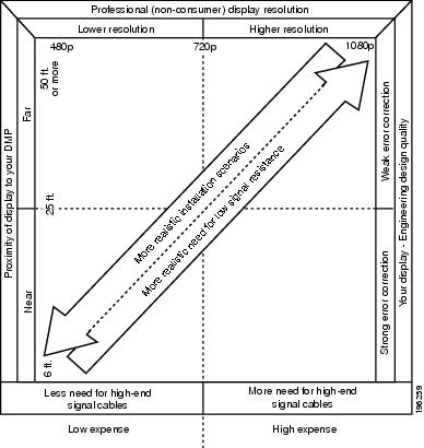
Beyond the general guidelines that Figure 1 illustrates, two additional factors might constrain which types of signal cable you can use.
- The technology, brand, and model of your display — Check its product documentation to understand its compatibility with various signal cable types.
- The DMP model — Table 2 states which I/O ports are available on various DMP models. (Alternatively, if the table does not describe your DMP model, see its datasheet at http://www.cisco.com/go/dms/dmp/datasheets.) Your packing list states which signal cables Cisco planned to ship with your DMP.
Understand How to Work Around the Low Signal Quality of Composite Video

Note![]() When video signals are transmitted through a composite cable, image quality suffers. When you use a composite cable and your DMP shows any web-based media, small text might be difficult to read in TVzilla. To work around this limitation, you can lower the browser resolution setting in DMPDM.
When video signals are transmitted through a composite cable, image quality suffers. When you use a composite cable and your DMP shows any web-based media, small text might be difficult to read in TVzilla. To work around this limitation, you can lower the browser resolution setting in DMPDM.
Procedures
- Use an HDMI Connection
- Use a Connection that Combines HDMI with DVI
- Connect to a Touchscreen
- Connect to an Analog Display or Projector
Use an HDMI Connection

Timesaver Is your display a touchscreen? If so, this topic is not for you. Instead, see the “Connect to a Touchscreen” section.
Step 1![]() Connect the HDMI cable to the HDMI interface on the back panel of your DMP.
Connect the HDMI cable to the HDMI interface on the back panel of your DMP.
Step 2![]() Connect the other end of the cable to your presentation system.
Connect the other end of the cable to your presentation system.
Step 3![]() Turn On the presentation system
Turn On the presentation system![]() .
.
Step 4![]() Stop. You have completed this procedure.
Stop. You have completed this procedure.
Use a Connection that Combines HDMI with DVI
Timesaver Is your display a touchscreen? If so, this topic is not for you. Instead, see the “Connect to a Touchscreen” section.
HDMI and DVI differ in their support for audio signals and use connectors that are shaped differently, but otherwise are identical. Thus, an adapter can help you to connect to your DMP any presentation system that supports DVI but not HDMI. When you do this, however, you must also use a separate signal cable to transmit audio signals, or there will not be any audio.
Step 1![]() Make connections for video.
Make connections for video.
a.![]() Connect the HDMI cable to the HDMI interface on the back panel of your DMP.
Connect the HDMI cable to the HDMI interface on the back panel of your DMP.
b.![]() Fasten an HDMI-to-DVI adapter to the free end of the cable.
Fasten an HDMI-to-DVI adapter to the free end of the cable.
c.![]() Connect the free end of the DVI adapter to the corresponding interface on your presentation system.
Connect the free end of the DVI adapter to the corresponding interface on your presentation system.
Step 2![]() Make connections for audio.
Make connections for audio.
a.![]() Plug the 3.5mm audio jack into the Audio interface on the back panel of your DMP.
Plug the 3.5mm audio jack into the Audio interface on the back panel of your DMP.
b.![]() Connect the other end of the audio cable to the corresponding interface on your presentation system.
Connect the other end of the audio cable to the corresponding interface on your presentation system.
Step 3![]() If the presentation system is not already turned on, turn it On now.
If the presentation system is not already turned on, turn it On now.
Step 4![]() Stop. You have completed this procedure.
Stop. You have completed this procedure.
Connect to a Touchscreen
Tip![]() Some touchscreens work as designed only after they are calibrated manually. If your touchscreen is one of these, its calibration occurs during a later stage of DMP setup. The list of related topics for this procedure states where you can learn about calibration.
Some touchscreens work as designed only after they are calibrated manually. If your touchscreen is one of these, its calibration occurs during a later stage of DMP setup. The list of related topics for this procedure states where you can learn about calibration.
DMP connections to a touchscreen are mostly the same as for other digital displays. However, touchscreens employ a special cable that supports interactivity through touch. This might be either an RS-232 serial cable or a USB cable, depending on the touchscreen model. Although some models support both cable types for interactivity, you can use only one type at a time.
- Verify that your DMP model supports touchscreen technologies and that we support the touchscreen brand, model, and device driver that you will use. See http://www.cisco.com/go/dms/compatibility.
- Check the documentation for your touchscreen to learn whether it requires a serial connection or a USB connection to your DMP, or if it supports both.
Step 1![]() Connect an HDMI cable to the HDMI interface on the back panel of your DMP.
Connect an HDMI cable to the HDMI interface on the back panel of your DMP.
Step 2![]() Connect the other end to your touchscreen.
Connect the other end to your touchscreen.
If your touchscreen supports DVI connections and not HDMI connections:
- Fasten an HDMI-to-DVI adapter to the free end of the cable.
- Connect the free end of the DVI adapter to the corresponding interface on your touchscreen.
Tip You can use an HDMI splitter or other supported method to attach multiple presentation systems to a DMP. However, only one of these systems can be a touchscreen.
Step 3![]() Do only one of the following.
Do only one of the following.
- Connect a USB cable to the USB interface on the back panel of your DMP. Then, connect the other end to your touchscreen.
If your DMP model has only one USB connector, you might prefer to connect an external hard drive there for added local storage. In this case, an RS-232 serial cable would be the better choice for connecting a touchscreen to your DMP.
- Connect an RS-232 serial cable to the RS232 interface on the back panel of your DMP. Then, connect the other end to your touchscreen.
Step 4![]() Turn On the touchscreen.
Turn On the touchscreen.
Tip Does a message on the touchscreen say that it must download a “characterization” file? This happens only when your touchscreen uses technologies from Elo TouchSystems and when you have never turned it On previously (or after its CF card is reformatted). When you see this message, please disregard it. The touchscreen will obtain its characterization file automatically during a later stage of DMP setup.
Step 5![]() Stop. You have completed this procedure.
Stop. You have completed this procedure.
Connect to an Analog Display or Projector
Tip![]() DMPs support connections to analog presentation systems,. However, we recommend strongly that you use digital presentation systems whenever possible.
DMPs support connections to analog presentation systems,. However, we recommend strongly that you use digital presentation systems whenever possible.
Step 1![]() Make connections for video.
Make connections for video.
a.![]() Plug one yellow jack from the RCA video cable into the CVBS interface on the back panel of your DMP.
Plug one yellow jack from the RCA video cable into the CVBS interface on the back panel of your DMP.
b.![]() Connect the free end of this cable to the corresponding interface on your presentation system.
Connect the free end of this cable to the corresponding interface on your presentation system.
Step 2![]() Make connections for audio.
Make connections for audio.
a.![]() Plug the 3mm jack on the RCA audio cable into the AUDIO interface on the back panel of your DMP.
Plug the 3mm jack on the RCA audio cable into the AUDIO interface on the back panel of your DMP.
b.![]() Connect the free end of this cable to the corresponding interface on your presentation system.
Connect the free end of this cable to the corresponding interface on your presentation system.
Step 3![]() If the presentation system is not already turned on, turn it On now.
If the presentation system is not already turned on, turn it On now.
Step 4![]() Stop. You have completed this procedure.
Stop. You have completed this procedure.
 Feedback