Cisco UCS C3160 Server Installation and Service Guide
Bias-Free Language
The documentation set for this product strives to use bias-free language. For the purposes of this documentation set, bias-free is defined as language that does not imply discrimination based on age, disability, gender, racial identity, ethnic identity, sexual orientation, socioeconomic status, and intersectionality. Exceptions may be present in the documentation due to language that is hardcoded in the user interfaces of the product software, language used based on RFP documentation, or language that is used by a referenced third-party product. Learn more about how Cisco is using Inclusive Language.
- Updated:
- September 26, 2014
Chapter: Overview
Overview
This chapter provides an overview of the Cisco UCS C3160 high-density storage server.
Front Panel Features
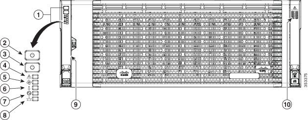
Figure 1-1 shows the front panel features of the system. The system is shown with the removable front bezel installed.
See Status LEDs and Buttons for explanations of LED states.
Figure 1-1 Front Panel Features
|
|
|
||
|
|
System Power button/LED (power shutdown for the entire system) |
|
|
|
|
|
||
|
|
|
||
|
|
|
Rear Panel Features
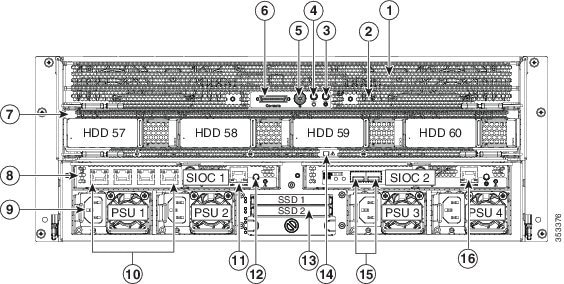
Figure 1-2 shows the rear panel features of the system.
See Status LEDs and Buttons for explanations of LED states.
Figure 1-2 Rear Panel Features
Replaceable Component Locations
This section contains the following topics:
- Replaceable Components Inside the Main Chassis
- Components Inside the Server Node
- Components Inside the System I/O Controller
Replaceable Components Inside the Main Chassis
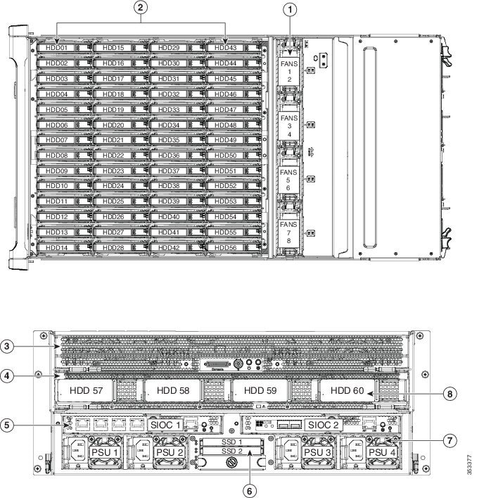
This section shows the locations of the replaceable components that are inside the main chassis. Some components are accessible from the rear panel and others are accessible by opening the top covers.
The top view of the system in Figure 1-3 shows the top covers open.

Note![]() The internal drives and cooling fans in the system are hot-swappable and are accessed by opening the top covers. When you rack and cable the system, be sure to allow enough slack in the power and other cables so that the system can be pulled out on the slide rails far enough to allow clearance for opening the top covers.
The internal drives and cooling fans in the system are hot-swappable and are accessed by opening the top covers. When you rack and cable the system, be sure to allow enough slack in the power and other cables so that the system can be pulled out on the slide rails far enough to allow clearance for opening the top covers.
Figure 1-3 Replaceable Components Inside the Main Chassis (Top View and Rear View)
|
|
Fan modules (four, hot-swappable) Each fan module contains two fans. Even numbers are upper fans, odd numbers are lower fans. |
|
|
|
|
Internal drive bays (up to 56 3.5-inch drives, hot-swappable) |
|
|
|
|
See also Components Inside the Server Node. |
|
|
|
|
|
3.5-inch drives (up to four in the optional drive expander module) |
Components Inside the Server Node
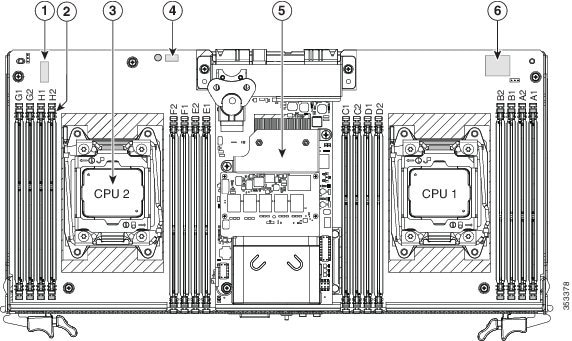
This section shows the locations of the replaceable components that are inside the server node, which is accessible from the rear of the chassis. The view shown is with the server node removed from the system and with the cover of the server node removed.
Figure 1-4 Replaceable Components Inside the Server Node
|
|
|
||
|
|
|
Cisco modular RAID controller card with SuperCap power module (backup) attached |
|
|
|
|
Internal USB port for USB thumb-drive (accessible with the node cover on) |
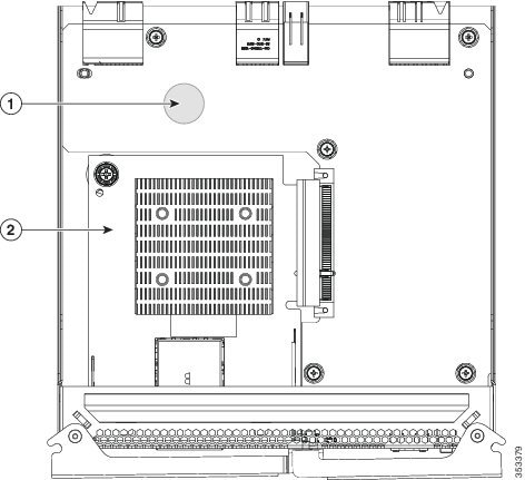
Components Inside the System I/O Controller
This section shows the locations of the replaceable components that are inside the system I/O controller, which is accessible from the rear of the chassis. The view shown is with the cover of the module removed.
Figure 1-5 Replaceable Components Inside the System I/O Controller
|
|
|
Adapter card (either dual-port 10 Gb SFP+ or quad-port 1 Gb RJ-45) |
System Features Overview
Table 1-1 lists the features of the system.
Two Intel Xeon E5-2600 v2 Series processors inside the server node. |
|
The system has the following storage options:
All drives are hot-swappable1. |
|
There is one dedicated mezzanine-style socket for a RAID controller with a 1-GB or 4-GB cache inside the server node. For a list of supported RAID controller options, see RAID Controller Considerations. |
|
The optional supercap power module (SCPM) mounts to the RAID controller card that is inside the server node. |
|
The system can have one or two system I/O controllers (SIOCs). These each provide rear-panel connectivity. The ports differ, depending on which adapter card is installed in the SIOC: – – – The server node also has one rear-panel KVM connector that can be used with a KVM cable, which provides two USB, one VGA, and one serial connector. |
|
The system includes one internal USB 2.0 slot inside the server node. |
|
Two or four power supplies, 1050 W each (hot-swappable and redundant as 2+2). |
|
Four internal fan modules that pull front-to-rear cooling, hot-swappable. Each fan module contains two fans. |
|
Cisco Integrated Management Controller (Cisco IMC) firmware. Depending on your NIC mode settings, the Cisco IMC can be accessed through the |
|
1.Hot-swappable = No preconditioning of the component is required before removal while the system is powered on. |
 Feedback