Cisco and Hitachi Adaptive Solutions for SAP HANA TDI with Scale-Out Storage Design Guide
Available Languages

Cisco and Hitachi Adaptive Solutions for SAP HANA TDI with Scale-Out Storage Design Guide
Last Updated: November 20, 2019
About the Cisco Validated Design Program
The Cisco Validated Design (CVD) program consists of systems and solutions designed, tested, and documented to facilitate faster, more reliable, and more predictable customer deployments. For more information, go to:
http://www.cisco.com/go/designzone.
ALL DESIGNS, SPECIFICATIONS, STATEMENTS, INFORMATION, AND RECOMMENDATIONS (COLLECTIVELY, "DESIGNS") IN THIS MANUAL ARE PRESENTED "AS IS," WITH ALL FAULTS. CISCO AND ITS SUPPLIERS DISCLAIM ALL WARRANTIES, INCLUDING, WITHOUT LIMITATION, THE WARRANTY OF MERCHANTABILITY, FITNESS FOR A PARTICULAR PURPOSE AND NONINFRINGEMENT OR ARISING FROM A COURSE OF DEALING, USAGE, OR TRADE PRACTICE. IN NO EVENT SHALL CISCO OR ITS SUPPLIERS BE LIABLE FOR ANY INDIRECT, SPECIAL, CONSEQUENTIAL, OR INCIDENTAL DAMAGES, INCLUDING, WITHOUT LIMITATION, LOST PROFITS OR LOSS OR DAMAGE TO DATA ARISING OUT OF THE USE OR INABILITY TO USE THE DESIGNS, EVEN IF CISCO OR ITS SUPPLIERS HAVE BEEN ADVISED OF THE POSSIBILITY OF SUCH DAMAGES.
THE DESIGNS ARE SUBJECT TO CHANGE WITHOUT NOTICE. USERS ARE SOLELY RESPONSIBLE FOR THEIR APPLICATION OF THE DESIGNS. THE DESIGNS DO NOT CONSTITUTE THE TECHNICAL OR OTHER PROFESSIONAL ADVICE OF CISCO, ITS SUPPLIERS OR PARTNERS. USERS SHOULD CONSULT THEIR OWN TECHNICAL ADVISORS BEFORE IMPLEMENTING THE DESIGNS. RESULTS MAY VARY DEPENDING ON FACTORS NOT TESTED BY CISCO.
CCDE, CCENT, Cisco Eos, Cisco Lumin, Cisco Nexus, Cisco StadiumVision, Cisco TelePresence, Cisco WebEx, the Cisco logo, DCE, and Welcome to the Human Network are trademarks; Changing the Way We Work, Live, Play, and Learn and Cisco Store are service marks; and Access Registrar, Aironet, AsyncOS, Bringing the Meeting To You, Catalyst, CCDA, CCDP, CCIE, CCIP, CCNA, CCNP, CCSP, CCVP, Cisco, the Cisco Certified Internetwork Expert logo, Cisco IOS, Cisco Press, Cisco Systems, Cisco Systems Capital, the Cisco Systems logo, Cisco Unified Computing System (Cisco UCS), Cisco UCS B-Series Blade Servers, Cisco UCS C-Series Rack Servers, Cisco UCS S-Series Storage Servers, Cisco UCS Manager, Cisco UCS Management Software, Cisco Unified Fabric, Cisco Application Centric Infrastructure, Cisco Nexus 9000 Series, Cisco Nexus 7000 Series. Cisco Prime Data Center Network Manager, Cisco NX-OS Software, Cisco MDS Series, Cisco Unity, Collaboration Without Limitation, EtherFast, EtherSwitch, Event Center, Fast Step, Follow Me Browsing, FormShare, GigaDrive, HomeLink, Internet Quotient, IOS, iPhone, iQuick Study, LightStream, Linksys, MediaTone, MeetingPlace, MeetingPlace Chime Sound, MGX, Networkers, Networking Academy, Network Registrar, PCNow, PIX, PowerPanels, ProConnect, ScriptShare, SenderBase, SMARTnet, Spectrum Expert, StackWise, The Fastest Way to Increase Your Internet Quotient, TransPath, WebEx, and the WebEx logo are registered trademarks of Cisco Systems, Inc. and/or its affiliates in the United States and certain other countries.
All other trademarks mentioned in this document or website are the property of their respective owners. The use of the word partner does not imply a partnership relationship between Cisco and any other company. (0809R)
© 2019 Cisco Systems, Inc. All rights reserved.
Table of Contents
Cisco Unified Computing System
Cisco UCS Fabric Interconnects
Cisco UCS 2304 XP Fabric Extenders
Cisco UCS 5108 Blade Server Chassis
Cisco UCS 1300 Series Virtual Interface Cards (VICs)
Cisco UCS B-Series Blade Servers
Cisco Nexus 9000 Series Switch
Hitachi Virtual Storage Platform Storage Systems
Storage Virtualization Operating System RF
Hitachi Virtual Storage Platform G Series and F Series
Hitachi Virtual Storage Platform 5000 Series
SAP HANA Tailored Data Center Integration
SAP HANA Design Considerations
Hardware Requirements for the SAP HANA Database
Scale and Performance Consideration
LUN Multiplicity per HBA and Different Pathing Options
Cisco Nexus 9000 Series vPC Best Practices
Cisco Validated Designs (CVDs) are systems and solutions that are designed, tested, and documented to facilitate and improve customer deployments. CVDs incorporate a wide range of technologies, products and best-practices into a portfolio of solutions that address the business needs of our customers.
Cisco and Hitachi work together to deliver a converged infrastructure solution that helps enterprise businesses meet the challenges of today and position themselves for the future. Leveraging decades of industry expertise and superior technology, Cisco and Hitachi offer a resilient, agile, flexible foundation for today’s businesses. In addition, the Cisco and Hitachi partnership extends beyond a single solution, enabling businesses to benefit from their ambitious roadmap of evolving technologies such as advanced analytics, IoT, cloud, and edge capabilities. With Cisco and Hitachi, organizations can confidently take the next step in their modernization journey and prepare themselves to take advantage of new business opportunities enabled by innovative technology.
The Cisco and Hitachi Adaptive Solutions for SAP HANA Tailored Data Center Integration solution described in this document is a validated reference architecture utilizing best practices from Cisco and Hitachi to build SAP HANA® Tailored Data Center Integration (TDI) environments. The solution is built on Cisco Unified Computing System™ (Cisco UCS) using the unified software release to support the Cisco UCS hardware platforms for Cisco UCS B-Series Blade Servers, Cisco UCS 6332 Fabric Interconnects, Cisco Nexus 9000 Series switches, Cisco MDS Fiber channel switches, and Hitachi Virtual Storage Platform F Series or G Series.
Additionally, it includes the validated Intel® Optane™ DC Persistent Memory Modules (DCPMM). The recommended solution architecture supports both Red Hat Enterprise Linux for SAP HANA and SUSE Linux Enterprise Server for SAP Applications.
Introduction
Enterprise data centers have a need for scalable and reliable infrastructure that can be implemented in an intelligent, policy driven manner. This implementation needs to be easy to use, and deliver application agility, so IT teams can provision applications quickly and resources can be scaled up (or down) in minutes.
Cisco and Hitachi Adaptive Solutions for SAP HANA Tailored Data Center Integration provides a best practice data center architecture to meet the needs of enterprise customers. The solution offers orchestrated efficiency across the data path with an intelligent system that helps anticipate and navigate challenges as you grow. The architecture builds a self-optimizing data center that automatically spreads workloads across devices to ensure consistent utilization and performance. The solution helps organizations to effectively plan infrastructure growth and eliminate the budgeting guesswork with predictive risk profiles that identify historical trends.
Organizations experience a 5-year ROI of 483% with Cisco UCS Converged Infrastructure solutions, Businesses experience 46% lower IT infrastructure costs with Cisco UCS Integrated Infrastructure solutions. Organizations can realize a 5-year total business benefit of $13M per organization with Cisco UCS Converged Infrastructure solutions. The break-even period with Cisco UCS Converged Infrastructure solutions is seven months. Businesses experience 66% lower ongoing administrative and management costs with Cisco UCS Manager (Scaramella, Rutten, & Marden, 2016).
SAP HANA is SAP SE’s implementation of in-memory database technology. The SAP HANA database combines transactional and analytical SAP workloads and hereby takes advantage of the low-cost main memory (RAM), data-processing capabilities of multicore processors, and faster data access. SAP HANA offers a multi-engine, query-processing environment that supports relational data (with both row- and column-oriented physical representations in a hybrid engine) as well as a graph and text processing for semi-structured and unstructured data management within the same system. SAP HANA TDI solution offers a more open and flexible way for integrating SAP HANA into the data center by reusing existing enterprise storage hardware, thereby reducing hardware costs. The SAP HANA TDI option enables organizations to run multiple SAP HANA production systems on a shared infrastructure. It also enables customers to run the SAP application servers and SAP HANA database hosted on the same infrastructure.
For more information about SAP HANA, see the SAP help portal: http://help.sap.com/hana.
This reference architecture highlights the resiliency, cost benefit, and ease of deployment of an SAP HANA Storage TDI solution, whether in single node or multi node configuration. The single node SAP HANA Scale-Up architecture composes the Hitachi Virtual Storage Platform (VSP) connecting through the Cisco MDS multilayer switches to Cisco Unified Computing System and is further enabled with the Cisco Nexus family of switches. The distributed node SAP HANA Scale-Out architecture adds the Hitachi NAS Platform (HNAS) to the solution connecting through the Cisco Nexus family switches to enable shared file system access.
Audience
The audience for this document includes, but is not limited to; data center architects, sales engineers, field consultants, professional services, IT managers, SAP Solution architects, and customers who want to modernize their infrastructure to meet Service Level Agreements (SLAs) and the business needs at any scale.
What’s New in this Release?
This reference architecture now includes the most current Cisco hardware and includes Scale-Out SAP HANA for TDI environments:
· Support for the Cisco UCS 4.0(4) unified software release.
· Cisco UCS B200 M5 and B480 M5 Blade Servers with the second-generation Intel® Xeon® Scalable processors.
· Support for Intel® Optane™ Data Center persistent memory modules (DCPMM)
· SAP HANA Scale-Out validation with Hitachi NAS Platform (HNAS)
Purpose of this Document
This document delivers an end-to-end design for the SAP HANA Tailored Data Center Integration using Cisco UCS, Hitachi VSP and Hitachi NAS, along with Cisco Nexus and MDS switches. It serves as the design guide for this solution.
It helps organizations to
· Work confidently with an unmatched 100% data availability guarantee, minimal downtime, and data loss protection.
· Run mission-critical applications efficiently by independently and automatically scaling compute and storage workloads.
· Monitor Service Level Objectives (SLOs) to ensure SLA compliance with integrated alerts for service-level thresholds and anomaly detection.
· Ensure employees have continuous, scalable data access with real-time data mirroring capabilities.
· Unify and automate the control of server, network, and storage components to simplify resource provisioning and maintenance.
· Easily test and implement new technologies that drive the business forward without impacting priorities or workloads.
Solution Summary
The Cisco and Hitachi Adaptive Solutions for SAP HANA Tailored Data Center Integration is a resilient, agile, flexible infrastructure, leveraging the strengths of both companies, Cisco and Hitachi. The solution uses the following family of infrastructure components for the compute, storage and networking and operating system layer:
· Cisco Unified Computing System (Cisco UCS) B-Series Blade Servers
· Cisco Nexus 9000 switches and Cisco MDS 9000 multilayer switches
· Hitachi Virtual Storage Platform (VSP) storage systems
· Hitachi NAS Platform (HNAS)
· SUSE Linux Enterprise Server for SAP Applications 15
· Red Hat Linux Enterprise for SAP HANA 7
The SAP HANA TDI environment has been validated for both SUSE Linux Enterprise Server (SLES) for SAP Applications and Red Hat Enterprise Linux (RHEL) for SAP HANA. The specific products listed in this design guide and the accompanying deployment guides have gone through a battery of validation tests confirming functionality and resilience for the listed components.
The solution uses Cisco UCS B-Series servers to provide the converged infrastructure for the data center. It integrates into the same converged infrastructure validated as Virtual Server Infrastructure (VSI), which is a validated approach for deploying Cisco and Hitachi technologies as private cloud infrastructure. The documented CVD is available here: Cisco and Hitachi Adaptive Solutions for Converged Infrastructure Design Guide.
Figure 1 Architecture of Cisco and Hitachi Adaptive Solutions for SAP HANA TDI
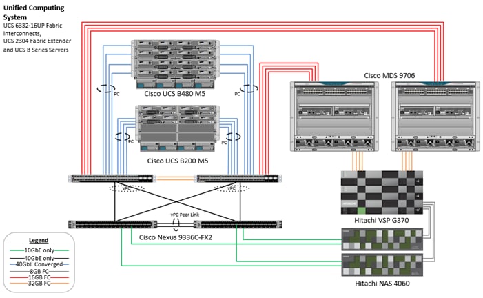
This design presents a validated reference architecture, that describes the specifics of the products utilized within the Cisco lab. However, equivalent supported products can be used which are certified for the specific SAP HANA workload and listed within Cisco’s and Hitachi’s published compatibility matrixes.
This section provides a technical overview of the compute, network, storage and management components in this solution. For additional information on any of the components covered in this section refer to the Solution References.
Cisco Unified Computing System
Cisco Unified Computing System (Cisco UCS) is a next-generation data center platform that integrates computing, networking, storage access, and virtualization resources into a cohesive system designed to reduce total cost of ownership and increase business agility. The system integrates a low-latency, lossless 10-100 Gigabit Ethernet unified network fabric with enterprise-class, x86-architecture servers. The system is an integrated, scalable, multi-chassis platform with a unified management domain for managing all resources.
Cisco Unified Computing System consists of the following subsystems:
· Compute - The compute piece of the system incorporates servers based on the Second-Generation Intel® Xeon® Scalable processors. Servers are available in blade and rack form factor, managed by Cisco UCS Manager.
· Network - The integrated network fabric in the system provides a low-latency, lossless, 10 and 40Gbps unified Ethernet fabric. Networks for LAN, SAN and management access are consolidated within the fabric. The unified fabric uses the innovative Single Connect technology to lower costs by reducing the number of network adapters, switches, and cables. This in turn lowers the power and cooling needs of the system.
· Virtualization - The system unleashes the full potential of virtualization by enhancing the scalability, performance, and operational control of virtual environments. Cisco security, policy enforcement, and diagnostic features are now extended into virtual environments to support evolving business needs.
· Storage access – Cisco UCS system provides consolidated access to both SAN storage and Network Attached Storage (NAS) over the unified fabric. This provides customers with storage choices and investment protection. Also, the server administrators can pre-assign storage-access policies to storage resources, for simplified storage connectivity and management leading to increased productivity.
· Management: The system uniquely integrates compute, network and storage access subsystems, enabling it to be managed as a single entity through Cisco UCS Manager software. Cisco UCS Manager increases IT staff productivity by enabling storage, network, and server administrators to collaborate on Service Profiles that define the desired physical configurations and infrastructure policies for applications. Service Profiles increase business agility by enabling IT to automate and provision resources in minutes instead of days.
Cisco UCS Differentiators
Cisco Unified Computing Systems have revolutionized the way servers are managed in data center and provide several unique differentiators that are outlined below:
· Embedded Management — Servers in Cisco UCS are managed by embedded software in the Fabric Interconnects, eliminating the need for any external physical or virtual devices to manage the servers.
· Unified Fabric — Cisco UCS uses a wire-once architecture, where a single Ethernet cable is used from the FI from the server chassis for LAN, SAN and management traffic. Adding compute capacity does not require additional connections. This converged I/O reduces overall capital and operational expenses.
· Auto Discovery — By simply inserting a blade server into the chassis or a rack server to the fabric interconnect, discovery of the compute resource occurs automatically without any management intervention. The combination of unified fabric and auto-discovery enables the wire-once architecture of Cisco UCS, where compute capability of Cisco UCS can be extended easily while keeping the existing external connectivity to LAN, SAN and management.
· Policy Based Resource Classification — Once a compute resource is discovered, it can be automatically classified to a resource pool based on policies defined which is particularly useful in cloud computing.
· Combined Rack and Blade Server Management — Cisco UCS Manager is hardware form factor agnostic and can manage both blade and rack servers under the same management domain.
· Model based Management Architecture — Cisco UCS Manager architecture and management database is model based, and data driven. An open XML API is provided to operate on the management model which enables easy and scalable integration of Cisco UCS Manager with other management systems.
· Policies, Pools, and Templates — The management approach in Cisco UCS Manager is based on defining policies, pools and templates, instead of cluttered configuration, which enables a simple, loosely coupled, data driven approach in managing compute, network and storage resources.
· Policy Resolution — In Cisco UCS Manager, a tree structure of organizational unit hierarchy can be created that mimics the real-life tenants and/or organization relationships. Various policies, pools and templates can be defined at different levels of organization hierarchy.
· Service Profiles and Stateless Computing — A service profile is a logical representation of a server, carrying its various identities and policies. This logical server can be assigned to any physical compute resource as far as it meets the resource requirements. Stateless computing enables procurement of a server within minutes, which used to take days in legacy server management systems.
· Built-in Multi-Tenancy Support — The combination of a profiles-based approach using policies, pools and templates and policy resolution with organizational hierarchy to manage compute resources makes Cisco UCS Manager inherently suitable for multi-tenant environments, in both private and public clouds.
· Extended Memory — The enterprise-class Cisco UCS Blade Servers extends the capabilities of Cisco’s Unified Computing System portfolio in a half-width of full-width blade form factor. It harnesses the power of the latest Intel® Xeon® Scalable Series processor family CPUs and Intel® Optane DC Persistent Memory (DCPMM) with up to 18 TB of RAM (using 256 GB DDR4 DIMMs and 512 GB DCPMM).
Cisco UCS Manager
Cisco UCS Manager (UCSM) provides unified, integrated management for all software and hardware components in Cisco UCS. Using Cisco Single Connect technology, it manages, controls, and administers multiple chassis for thousands of virtual machines. Administrators use the software to manage the entire Cisco Unified Computing System as a single logical entity through an intuitive graphical user interface (GUI), a command-line interface (CLI), or through a robust application programming interface (API).
Cisco UCS Manager is embedded into the Cisco UCS Fabric Interconnects using a clustered, active-standby configuration for high availability and provides a unified management interface that integrates server, network, and storage. Cisco UCS Manger performs auto-discovery to detect inventory, manage, and provision system components that are added or changed. It offers a comprehensive set of XML API for third party integration, exposes thousands of integration points and facilitates custom development for automation, orchestration, and to achieve new levels of system visibility and control.
Cisco Intersight
Cisco Intersight is Cisco’s new systems management platform that delivers intuitive computing through cloud-powered intelligence. This platform offers a more intelligent management level and enables IT organizations to analyze, simplify and automate their IT environments in ways that were not possible with prior generations of tools. This capability empowers organizations to achieve significant savings in Total Cost of Ownership (TCO) and to deliver applications faster to support new business initiatives.
The Cisco UCS platform uses model-based management to provision servers and fabric automatically, regardless of form factor. Cisco Intersight works in conjunction with Cisco UCS Manager and the Cisco Integrated Management Controller (IMC). By simply associating a model-based configuration with a resource through service profiles, your IT staff can consistently align policy, server personality, and workloads. These policies can be created once and used by IT staff with minimal effort to deploy servers. The result is improved productivity and compliance and lower risk of failures due to inconsistent configuration.
Cisco Intersight will be integrated with data center, hybrid cloud platforms and services to securely deploy and manage infrastructure resources across data center and edge environments. In addition, Cisco will provide future integrations to third-party operations tools to allow customers to use their existing solutions more effectively.
Cisco Intersight manages all Cisco UCS servers and switches in the solution and offers cloud-based, centralized management of Cisco UCS servers across all Enterprise locations and delivers unique capabilities such as:
· Integration with Cisco TAC for support and case management
· Proactive, actionable intelligence for issues and support based on telemetry data
· Compliance check through integration with Cisco Hardware Compatibility List (HCL)
· Centralized service profiles for policy-based configuration
More information on Cisco Intersight and the different editions is available on the web Cisco Intersight – Manage your systems anywhere.
Cisco UCS Fabric Interconnects
The Cisco UCS Fabric interconnects (FIs) provide a single point for connectivity and management for the entire Cisco UCS system. Typically deployed as an active-active pair, the system’s fabric interconnects integrate all components into a single, highly available management domain controlled by the Cisco UCS Manager. Cisco UCS FIs provide a single unified fabric for the system, with low-latency, lossless, cut-through switching that supports LAN, SAN and management traffic using a single set of cables.
The 3rd generation (6300) Fabric Interconnect provides the management and communication backbone for the Cisco UCS B-Series Blade Servers, UCS 5108 B-Series Server Chassis and UCS Managed C-Series Rack Servers. The One-Rack-Unit (1RU) Fabric Interconnect model featured in this design is the Cisco UCS 6332-16UP Fabric Interconnect. The Fabric Interconnects offer up to 2.24 Tbps throughput between the FI 6332 and the IOM 2304 per 5108 blade chassis. The switch has 24x40Gbps fixed Ethernet/FCoE ports with unified ports providing 16x1/10 Gbps Ethernet/FCoE or 4/8/16 Gbps FC ports. This model aims at FC storage deployments requiring high performance 16 Gbps FC connectivity to Cisco MDS switches or FC direct attached storage.
Figure 2 Cisco UCS 6332-16UP Fabric Interconnect
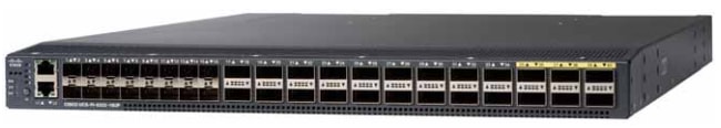
For more information, refer to Cisco UCS 6332-16UP Fabric Interconnect..
Cisco UCS 2304 XP Fabric Extenders
The Cisco UCS Fabric extenders (FEX) or I/O Modules (IOMs) multiplexes and forwards all traffic from servers in a blade server chassis to a pair of Cisco UCS Fabric Interconnects over a 40Gbps unified fabric links. All traffic, including traffic between servers on the same chassis, or different chassis, is forwarded to the parent fabric interconnect where Cisco UCS Manager runs, managing the profiles and polices for the servers. FEX technology was developed by Cisco. Up to two FEXs can be deployed in a chassis.
The Cisco UCS 2304 Fabric Extender has four 40 Gigabit Ethernet, FCoE-capable, Quad Small Form-Factor Pluggable (QSFP+) ports that connect the blade chassis to the fabric interconnect. Each Cisco UCS 2304 has four 40 Gigabit Ethernet ports connected through the midplane to each half-width slot in the chassis. Typically configured in pairs for redundancy, two fabric extenders provide up to 320 Gbps of I/O to the chassis.
Figure 3 Cisco UCS 2304 XP Fabric Extenders
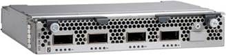
For more information, refer to the Cisco UCS 2304 Fabric Extender Data Sheet.
Cisco UCS 5108 Blade Server Chassis
The Cisco UCS 5108 Blade Server Chassis is a fundamental building block of the Cisco Unified Computing System, delivering a scalable and flexible blade server architecture. The Cisco UCS blade server chassis uses an innovative unified fabric with fabric-extender technology to lower TCO by reducing the number of network interface cards (NICs), host bus adapters (HBAs), switches, and cables that need to be managed, cooled, and powered. It is a 6-RU chassis that can house up to 8 x half-width or 4 x full-width Cisco UCS B-series blade servers. A passive mid-plane provides up to 80Gbps of I/O bandwidth per server slot and up to 160Gbps for two slots (full-width). The rear of the chassis contains two I/O bays to house a pair of Cisco UCS 2000 Series Fabric Extenders to enable uplink connectivity to FIs for both redundancy and bandwidth aggregation.
Figure 4 Cisco UCS 5108 Blade Server Chassis
For reference and more information, go to the Cisco UCS 5108 Blade Server Chassis web page.
Cisco UCS 1300 Series Virtual Interface Cards (VICs)
The Cisco UCS blade server has various Converged Network Adapters (CNA) options.
Cisco VIC 1340 Virtual Interface Card
The Cisco UCS Virtual Interface Card (VIC) 1340 is a 2-port 40-Gbps Ethernet or dual 4 x 10-Gbps Ethernet, Fiber Channel over Ethernet (FCoE)-capable modular LAN on motherboard (mLOM) designed exclusively for the Cisco UCS B-Series Blade Servers. When used in combination with an optional port expander, the Cisco UCS VIC 1340 capabilities is enabled for two ports of 40-Gbps Ethernet.
The Cisco UCS VIC 1340 enables a policy-based, stateless, agile server infrastructure that can present over 256 PCIe standards-compliant interfaces to the host that can be dynamically configured as either network interface cards (NICs) or host bus adapters (HBAs). In addition, the Cisco UCS VIC 1340 supports Cisco Data Center Virtual Machine Fabric Extender (VM-FEX) technology, which extends the Cisco UCS fabric interconnect ports to virtual machines, simplifying server virtualization deployment and management.
Cisco VIC 1380 Virtual Interface Card
The Cisco UCS Virtual Interface Card (VIC) 1380 is a dual-port 40-Gbps Ethernet, or dual 4 x 10 Fiber Channel over Ethernet (FCoE)-capable mezzanine card designed exclusively for the M5 generation of Cisco UCS B-Series Blade Servers. The card enables a policy-based, stateless, agile server infrastructure that can present over 256 PCIe standards-compliant interfaces to the host that can be dynamically configured as either network interface cards (NICs) or host bus adapters (HBAs). In addition, the Cisco UCS VIC 1380 supports Cisco Data Center Virtual Machine Fabric Extender (VM-FEX) technology, which extends the Cisco UCS fabric interconnect ports to virtual machines, simplifying server virtualization deployment and management.
Cisco UCS B-Series Blade Servers
Cisco UCS B-Series Blade Servers are based on Intel® Xeon® processors. They work with virtualized and non-virtualized applications to increase performance, energy efficiency, flexibility, and administrator productivity.
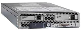
Cisco UCS B200 M5 Servers
The enterprise-class Cisco UCS B200 M5 Blade Server extends the Cisco UCS portfolio in a half-width blade form-factor. This B200 M5 server supports the first and second-generation Intel® Xeon® Scalable processors. The second-generation Intel® Xeon® Scalable processors introduce the support for the new Intel® Optane DC Persistent Memory Modules. These B200 M5 servers offer up to 3 terabytes (TB) of DDR4 memory or 7.5 TB using 12x128G DDR4 DIMMs and 12x512G Intel® Optane DCPMM nonvolatile memory technology.
Additionally, it offers two drives (SSD, HDD or NVMe), up to two optional NVIDIA GPUs and 80Gbps of total I/O to each server. One Cisco Virtual Interface Card (VIC) 1340 modular LAN on Motherboard (mLOM) adapter provides 40Gb FCoE connectivity to the unified fabric.
Figure 5 Cisco UCS B200 M5 Blade Server
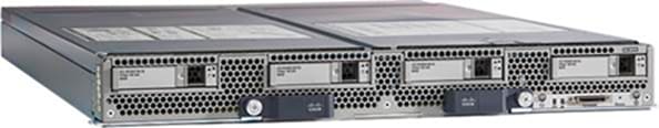
Cisco UCS B480 M5 Servers
The enterprise-class Cisco UCS B480 M5 Blade Server delivers market-leading performance, versatility, and density without compromise for memory-intensive mission-critical enterprise applications and virtualized workloads, among others. The Cisco UCS B480 M5 is a full-width blade server supported by the Cisco UCS 5108 Blade Server Chassis.
The Cisco UCS B480 M5 Blade Server offers four second-generation Intel® Xeon® Scalable CPUs and the new Intel® Optane DC Persistent Memory. These Cisco UCS B480 M5 servers offer up to 12 terabytes (TB) of DDR4 memory or 18 TB using 24x256G DDR4 DIMMs and 24x512G Intel® Optane DCPMM nonvolatile memory technology.
Additionally, it offers five mezzanine adapters and support for up to four optional NVIDIA GPUs, one Cisco UCS Virtual Interface Card (VIC) 1340 modular LAN on Motherboard (mLOM) and a dual-port 40-Gbps Ethernet Cisco UCS Virtual Interface Card (VIC) 1380. It will support the upcoming 4th generation VIC card as well.
Figure 6 Cisco UCS B480 M5 Blade Server
Cisco Nexus 9000 Series Switch
Cisco Nexus series switches provide an Ethernet switching fabric for communications between the Cisco UCS, Hitachi NAS Platform, and the rest of a customer’s network. There are many factors to consider when choosing the main data switch in this type of architecture to support both the scale and the protocols required for the resulting applications. All Nexus switch models including the Nexus 5000 and Nexus 7000 are supported in this design and may provide additional features such as FCoE or OTV. However, be aware that there may be slight differences in setup and configuration based on the switch used. The validation for this deployment leverages the Cisco Nexus 9300 series switches, which deliver high performance 100/40GbE ports, density, low latency, and exceptional power efficiency in a broad range of compact form factors.
The Cisco Nexus 9000 Series Switches offer both modular and fixed 10/40/100 Gigabit Ethernet switch configurations with scalability up to 60 Tbps of non-blocking performance with less than five-microsecond latency, wire speed VXLAN gateway, bridging, and routing support.
The Nexus featured in this design is the Nexus 9336C-FX2 in standalone Cisco NX-OS operation mode.
Figure 7 Cisco Nexus 9336C-FX2
The Nexus 9336C-FX2 implements Cisco Cloud Scale ASICs, giving flexible, and high port density, intelligent buffering, along with in-built analytics and telemetry. Supporting either Cisco ACI or NX-OS, the Nexus delivers a powerful 40/100Gbps platform offering up to 7.2 Tbps of bandwidth in a compact 1RU TOR switch.
Cisco MDS 9000 Series Switch
The Cisco MDS 9000 family of multilayer switches give a diverse range of storage networking platforms, allowing you to build a highly scalable storage network with multiple layers of network and storage management intelligence. Fixed and modular models implement 2-32 Gbps FC, 10-40Gbps FCoE/FCIP, and up to 48 Tbps of switching bandwidth.
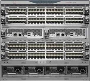
The MDS 9706 Multilayer Director is featured in this design as one of the available options within a Cisco MDS Family.
This six-slot switch presents a modular, redundant supervisor design, giving FC and FCoE line card modules, SAN extension capabilities, as well as NVMe over FC support on all ports. The MDS 9706 offers a lower TCO through SAN consolidation, high availability, traffic management and SAN analytics, along with management and monitoring capabilities available through Cisco Data Center Network Manager (DCNM).
Figure 8 Cisco MDS 9706 Switch
Hitachi Virtual Storage Platform Storage Systems
Hitachi Virtual Storage Platform is a highly scalable, true enterprise-class storage system that can virtualize external storage and provide virtual partitioning and quality of service for diverse workload consolidation. The abilities to securely partition port, cache and disk resources, and to mask the complexity of a multivendor storage infrastructure, make Virtual Storage Platform the ideal complement to mission-critical and Tier 1 business applications, VSP delivers the highest uptime and flexibility for your block-level storage needs, providing much-needed flexibility for enterprise environments.
With the addition of flash acceleration technology, a single VSP is now able to service more than 1 million random read IOPS. This extreme scale allows you to increase systems consolidation and virtual machine density by up to 100%, defer capital expenses and operating costs, and improve quality of service for open systems and virtualized applications.
VSP capabilities ensure that businesses can meet service level agreements (SLAs) and stay on budget by offering the following
· The industry's only 100% uptime warranty
· 3D scalable design
· 40 percent higher density
· 40 percent less power required
· Industry's leading virtualization
· Nondisruptive data migration
· Fewer administrative resources
· Resilient performance, less risk
The Hitachi Virtual Storage Platform G series family enables the seamless automation of the data center. It has a broad range of efficiency technologies that deliver maximum value while making ongoing costs more predictable. You can focus on strategic projects and to consolidate more workloads while using a wide range of media choices.
The benefits start with Hitachi Storage Virtualization Operating System RF. This includes an all new enhanced software stack that offers up to three times greater performance than previous midrange models, even as data scales to petabytes.
Virtual Storage Platform G series offers support for containers to accelerate cloud-native application development. Provision storage in seconds, and provide persistent data availability, all the while being orchestrated by industry leading container platforms. Moved these workloads into an enterprise production environment seamlessly, saving money while reducing support and management costs.
Storage Virtualization Operating System RF
Hitachi Storage Virtualization Operating System (SVOS) RF abstracts information from storage systems, virtualizes and pools available storage resources, and automates key data management functions such as configuration, mobility, optimization, and protection. This unified virtual environment enables you to maximize the utilization and capabilities of your storage resources while at the same time reducing operations overhead and risk. Standards-compatible for easy integration into IT environments, storage virtualization and management capabilities provide the utmost agility and control, helping you build infrastructures that are continuously available, automated, and agile.
SVOS RF is the latest version of SVOS. Flash performance is optimized with a patented flash-aware I/O stack, which accelerates data access. Adaptive inline data reduction increases storage efficiency while enabling a balance of data efficiency and application performance. Industry-leading storage virtualization allows SVOS RF to use third-party all-flash and hybrid arrays as storage capacity, consolidating resources for a higher ROI and providing a high-speed front-end to slower, less predictable arrays.
SVOS RF provides the foundation for superior storage performance, high availability, and IT efficiency. The enterprise-grade capabilities in SVOS RF include centralized management across storage systems and advanced storage features, such as active-active data centers and online migration between storage systems without user or workload disruption.
The features of SVOS RF include the following:
· Advanced efficiency providing user-selectable data reduction
· External storage virtualization
· Thin provisioning and automated tiering
· Flash performance acceleration
· Global-active device for distributed environments
· Deduplication and compression of data stored on internal flash drives
· Storage service-level controls
· Data-at-rest encryption
· Performance instrumentation across multiple storage platforms
· Centralized storage management
- Simplified: Hitachi Storage Advisor
- Advanced and powerful: Hitachi Command Suite, Command Control Interface
- For organizations that have their own management toolset, we include standards-based application program interfaces (REST APIs) that centralize administrative operations on a preferred management application.
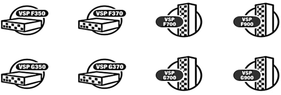
Hitachi Virtual Storage Platform G Series and F Series
Based on Hitachi's industry-leading storage technology, the all-flash Hitachi Virtual Storage Platform F350, F370, F700, and F900 and the Hitachi Virtual Storage Platform G350, G370, G700 and G900 include a range of versatile, high-performance storage systems that deliver flash-accelerated scalability, simplified management, and advanced data protection.
Key features of the Hitachi Virtual Storage Platform Fx00 models and Gx00 models include:
· Up to 2.4M IOPS performance
· 100% data-availability guarantee
· AI optimized operations
· Cloud optimization
· Enhanced integration for VMware, Windows, and Oracle environments
· Advanced active-active clustering, replication, and snapshots
· Active flash tiering and groundbreaking flash modules
With many enterprises implementing both private and public cloud services as part of their overall IT strategy, the ability to take advantage of this hybrid data migration solution is critical. The data migrator to cloud feature enables policy-driven, user-transparent, and automatic file tiering of less used (cold) files from unified models to private clouds, such as Hitachi Content Platform, and public clouds, such as Amazon S3 or Microsoft Azure. This approach frees up storage resources for more frequently accessed applications for Tier 1 storage, thus reducing overall storage expenditures.
Hitachi Accelerated Flash (HAF) storage delivers best-in-class performance and efficiency in the Hitachi VSP F series and VSP G series storage systems. HAF features patented flash module drives (FMDs) that are rack-optimized with a highly dense design that delivers greater than 338 TB effective capacity per 2U tray based on a typical 2:1 compression ratio. IOPS performance yields up to five times better results than that of enterprise solid-state drives (SSDs), resulting in leading performance, lowest bit cost, highest capacity, and extended endurance. HAF integrated with SVOS enables leading, real-application performance, lower effective cost, and superior consistent response times. Running on VSP F Series and G Series, HAF with SVOS RF enables transactions executed within sub-millisecond response even at petabyte scale.
· Key Features - HAF delivers outstanding value compared to enterprise SSDs. When compared to small-form-factor 1.92-TB SSDs, the HAF drives deliver better performance and response time.
· Second- and Third-generation Flash Modules - The FMD HD drives are designed to support concurrent, large I/O enterprise workloads and enable hyperscale efficiencies. At their core is an advanced embedded multicore flash controller that increases the performance of multilayer cell (MLC) flash to levels that exceed those achieved by more expensive single-level cell (SLC) flash SSDs. Their inline compression offload engine and enhanced flash translation layer empower the drives to deliver up to 80% data reduction (typically 2:1) at 10 times the speed of competing drives. With more raw capacity and inline, no-penalty compression, these drives enable better performance than the SSDs.
The architecture of the Hitachi Virtual Storage Platform Fx00 models and Gx00 models accommodates scalability to meet a wide range of capacity and performance requirements. The storage systems can be configured with the desired number and types of front-end module features for attachment to a variety of host processors. All drive and cache upgrades can be performed without interrupting user access to data, allowing you to hot add components as you need them for pay-as-you-grow scalability.
The Hitachi Virtual Storage Platform Fx00 models and Gx00 models have dual controllers that provide the interface to a data host. Each controller contains its own processor, dual in-line cache memory modules (DIMMs), cache flash memory (CFM), battery, and fans, and is provided with an Ethernet connection for out-of-band management using Hitachi Device Manager - Storage Navigator. If the data path through one controller fails, all drives remain available to hosts using a redundant data path through the other controller. The Hitachi Virtual Storage Platform Fx00 models and Gx00 models allow a defective controller to be replaced.
VSP G350, G370, G700, G900 models support a variety of drives, including HDDs, SSDs for the G350 and G370. The G700 and G900 provide additional support for FMD HD drives that are the foundation of the VSP F700 and F900 models.
The storage systems allow defective drives to be hot swapped without interrupting data availability. A hot spare drive can be configured to replace a failed drive automatically, securing the fault-tolerant integrity of the logical drive. Self-contained, hardware-based RAID logical drives provide maximum performance in compact external enclosures.
The VSP F350, F370, F700, F900 all-flash arrays bring together all-flash storage and the simplicity of built-in automation software with the proven resiliency and performance of Hitachi VSP technology. The all-flash arrays offer up to 2.4 million IOPS to meet the most demanding application requirements.
Easy-to-use replication management is included with the all-flash arrays with optional synchronous and asynchronous replication available for complete data protection. The all-flash arrays range in storage capacity from 1.4 PB (raw) up to 8.7 PB effective flash capacity and provide an all-flash solution that works seamlessly with other Hitachi infrastructure products through common management software and rich automation tools.
Hitachi Virtual Storage Platform Fx00 models and Gx00 models work with a service processor (SVP). The SVP provides out‑of‑band configuration and management of the storage system and collects performance data for key components to enable diagnostic testing and analysis.
The SVP is available as a physical device provided by Hitachi Vantara or as a software application:
· The physical SVP is a 1RU management server that runs Windows Embedded Standard 10.
· The SVP software application is installed on a customer-supplied server and runs on a customer-supplied version of Windows.
Hitachi storage units have been certified for SAP HANA TDI and are listed in the SAP Certified and Supported SAP HANA Hardware Directory. Best practices for Hitachi Storage systems in TDI environments are available, such as in SAP HANA Tailored Data Center Integration with Hitachi VSP F/G Storage Systems and SVOS RF.
For more information about SAP HANA TDI certified Hitachi storage refer to the Solution References section.
Hitachi Virtual Storage Platform 5000 Series
Based This enterprise-class, flash array evolution the Hitachi Virtual Storage Platform 5000 series (VSP) has an innovative, scale-out design optimized for NVMe (non-volatile memory express) and SCM (storage class memory). It achieves the following:
· Agility using NVMe — Speed, massive scaling with no performance slowdowns, intelligent tiering, and efficiency.
· Resilience — Superior application availability and flash resilience. Your data is always available, mitigating business risk.
· Storage simplified — Do more with less, integrate AI and ML (machine learning), simplify management, and save money and time with consolidation.
Hitachi NAS Platform 4060
Hitachi NAS Platform is an advanced and integrated network attached storage (NAS) solution. It provides a powerful tool for file sharing, file server consolidation, data protection, and business critical NAS workloads.
· Powerful hardware-accelerated file system with multi-protocol file services, dynamic provisioning, intelligent tiering, virtualization, and cloud infrastructure
· Seamless integration with Hitachi SAN storage, Hitachi Command Suite, and Hitachi Data Discovery Suite for advanced search and index
· Integration with Hitachi Content Platform for active archiving, regulatory compliance, and large object storage for cloud infrastructure
This solution uses NAS Platform 4060 file system modules for file system sharing of the global binary and configuration files of SAP HANA. There are two NAS Platform 4060 server nodes.
System Management Unit
Web Manager, the graphical user interface of the system management unit, provides front-end server administration and monitoring tools. It supports clustering and acts as a quorum device in a cluster. This solution uses an external virtual system management unit that manages two NAS Platform servers.
The section describes the SAP HANA system requirements defined by SAP and the architecture of the Cisco and Hitachi Adaptive Solutions for SAP HANA Tailored Data Center Integration.
SAP HANA Tailored Data Center Integration
SAP increases flexibility and provides an alternative to SAP HANA Appliances with SAP HANA® Tailored Data Center Integration. This includes many kinds of virtualization, network and storage technology. It is crucial to understand the possibilities and requirements of an SAP HANA TDI environment.
SAP provides documentation around SAP HANA TDI environments that explain the five phases of SAP HANA TDI as well as hardware and software requirements for the entire stack.
The certified and supported SAP HANA hardware directory lists the certified Hitachi enterprise storage as well as the certified Cisco UCS servers.
SAP HANA Design Considerations
Multiple implementation options are available specific to the SAP HANA TDI integration. This reference architecture describes non-virtualized SAP HANA environments.
SAP HANA System on a Single Node (Scale-Up)
A Scale-Up SAP HANA TDI solution is the simplest installation type. In general, this solution provides the best SAP HANA performance. All data and processes are located on the same server and do not require additional network considerations when it comes to internode communication for example. This solution is based on a standalone Cisco UCS Blade server and uses the fibre channel connected Hitachi VSP storage.
The network requirements for this option depend on the client and application access and storage connections. If a dedicated system replication or backup network is not required, a 10 GbE (access) network and the 16 Gbps fibre channel storage connection to access the SAP HANA data, log and shared filesystem are required to operate SAP HANA in a Scale-Up configuration.
The SAP HANA Hardware and Cloud Measurement Tool (HCMT) ensures the SAP HANA deployment meets the desired system and performance requirements defined by SAP.
Within this architecture a single Hitachi VSP F/G350 or F/G370 model serve up to 16 active SAP HANA servers. The larger Hitachi VSP F/G700 storage can serve 34 active SAP HANA servers and the Hitachi VSP F/G900 scales up to 40 active SAP HANA node per single storage platform.
SAP HANA System on Multiple Nodes (Scale-Out)
While an SAP HANA Scale-Up environment is the preferred installation method it will be necessary to distribute the SAP HANA database to multiple nodes if the amount of main memory doesn’t fit to keep the SAP HANA database in memory. Multiple, independent blade servers are combined to form one SAP HANA system and distribute the load among multiple servers.
In a distributed system, typically each index server is assigned to its own host to achieve maximum performance. It is possible to assign different tables to different hosts (partitioning the database), or a single table can be split across hosts (partitioning of tables). SAP HANA comes with an integrated high availability option, and single servers can be installed as standby hosts.
The Fibre Channel storage LUNs are mapped to the SAP HANA servers with a point-to-point connection. In the event of a failover to the standby host, the remapping of the logical volumes is managed by the SAP HANA Storage Connector API. SAN LUNs appear to the Operating System as disks. For shared SAP HANA binaries NFS/NAS storage is required and redundant connectivity to the corporate network via LAN (Ethernet) and to the storage via the Storage Area network (SAN) must always be configured
The network requirements for this option are higher than for Scale-Up HANA systems. In addition to the client and application access and fibre channel SAN, the Scale-Out environment require a node-to-node network as well as an NFS network towards the Hitachi NAS Platform. If you don’t need system replication or a backup network, a 10 Gigabit Ethernet (access) network and a mandatory minimum of 10 Gigabit Ethernet (node-to-node) and the 16 Gb fibre channel storage connection to access the SAP HANA data and log filesystem are required to operate SAP HANA in a Scale-Out configuration.
The SAP HANA Hardware and Cloud Measurement Tool (HCMT) ensures the SAP HANA deployment meets the desired system and performance requirements defined by SAP.
A single Hitachi VSP G/F350 or G/F370 model serve up to 16 active SAP HANA servers. The larger Hitachi VSP G/F700 storage can serve 34 active SAP HANA servers and the Hitachi VSP G/F900 scales up to 40 active SAP HANA node per single storage platform.
The maximum amount of active SAP HANA nodes in a Scale-Out SAP HANA TDI configuration is limited by SAP to 16 active SAP HANA servers.
Co-existing SAP HANA and SAP Application Workloads
With SAP HANA TDI it is possible to run SAP HANA on shared infrastructure that also hosts non-HANA workloads as standard SAP applications. Scenarios where SAP HANA database bare metal installation along with virtualized SAP application workloads are common in the datacenter. It is important to ensure appropriate storage IO and network bandwidth segregation is available, so HANA systems comfortably satisfy their storage and network KPIs for production support.
Scaling Up and Scaling Out of SAP HANA Systems
Hosting multiple scale-up and scale out systems requires proper sizing of the infrastructure with a clear compute node to storage system ratio. The number of compute nodes per Hitachi VSP must be determined based on the total number of SAP HANA nodes in the SAP system landscape and involves corresponding scaling of the associated compute gear and networking components based on port availability and usage.
Hardware Requirements for the SAP HANA Database
There are hardware and software requirements defined by SAP to run SAP HANA systems. This Cisco Validated Design uses guidelines provided by SAP.
Find additional resources and information on certified and supported SAP HANA hardware and software requirements to operate SAP HANA in the data center from the links provided in the Solution References.
CPU
The Cisco UCS Manager Release 4.0(4) introduce support for the second-generation Intel® Xeon® Scalable processors (Cascade Lake) CPUs. The Cisco UCS B-Series Blade Servers are capable to be configured with full or half size amount of Intel Xeon scalable family CPUs. The 28 cores per CPU Intel Xeon Platinum 8276 or 8280 CPUs are certified for SAP HANA environments.
Memory
The Cisco Integrated Management Controller (IMC) and Cisco UCS Manager Release 4.0(4) introduce support for Intel® Optane™ Data Center persistent memory modules (DCPMM) on Cisco UCS M5 servers based on the Second-Generation Intel ® Xeon® Scalable processors (Cascade Lake).
The Cisco UCS M5 servers can operate either with DDR4 DIMM memory only or with SAP HANA 2.0 SPS03 revision 35+ in various memory capacity ratios between Intel Optane DCPMM and DRAM DIMMs in the same system. The Cisco UCS M5 server will not function without any DRAM DIMMs installed.
Appropriate SAP HANA memory sizing must be performed before considering an Intel Optane DCPMM configuration. Detailed information on the configuration and management is available in the whitepaper Cisco UCS: Configuring and Managing Intel Optane Data Center Persistent Memory Modules.
In DDR4 DIMM memory only population the following configuration rules apply:
· Homogenous symmetric assembly of dual in-line memory modules (DIMMs) for example, DIMM size or speed should not be mixed
· Maximum use of all available memory channels
· Maximum supported Memory Configuration
- 3 TB on Cisco B200 M5 Servers with 2 CPUs
- 6 TB on Cisco B480 M5 Servers with 4 CPUs
In Intel Optane DCPPM/DDR4 DIMM mixed memory population the following rules apply:
· The installed DDR4 DIMMs must all be the same size
· The installed DCPMMs must all be the same size
· Balanced memory population and maximum use of all available memory channels
· Maximum supported Memory Configuration
- 7.5 TB on Cisco B200 M5 Servers with 2 CPUs
- 18 TB on Cisco B480 M5 Servers with 4 CPUs
Network
An SAP HANA data center deployment can range from a database running on a single host to a complex distributed system. Distributed systems can get complex with multiple hosts located at a primary site having one or more secondary sites; supporting a distributed multi-terabyte database with full fault and disaster recovery.
SAP HANA has different types of network communication channels to support the different SAP HANA scenarios and setups like:
· Client zone: Different clients, such as SQL clients on SAP application servers, browser applications using HTTP/S to the SAP HANA XS server and other data sources (such as BI) need a network communication channel to the SAP HANA database.
· Internal zone: The internal zone covers the communication between hosts in a distributed SAP HANA system as well as the communication used by SAP HANA system replication between two SAP HANA sites.
· Storage zone: Although SAP HANA holds the bulk of its data in memory, the data is also saved in persistent storage locations. In most cases, the preferred storage solution involves separate, externally attached storage subsystem devices capable of providing dynamic mount-points for the different hosts, according to the overall landscape. A storage area network (SAN) is used for storage connectivity.
For more information about SAP HANA TDI network requirements refer to the Solution References.
Storage
SAP HANA is an in-memory database which uses storage devices to save a persistent copy of the data for the purpose of startup and fault recovery without data loss. The choice of the specific storage technology is driven by various requirements like size, performance and high availability. To use a storage system in the SAP HANA TDI option, the storage must be certified as SAP HANA certified Enterprise Storage.
The Solution References section provides links to the SAP HANA certified hardware directory and a white paper which discuss all relevant information about the storage requirements.
![]() The solution needs to pass the SAP HANA Hardware and Cloud Measurement Tool (HCMT) check successfully prior of reporting IO performance related SAP HANA incidents.
The solution needs to pass the SAP HANA Hardware and Cloud Measurement Tool (HCMT) check successfully prior of reporting IO performance related SAP HANA incidents.
File System Layout
Figure 9 illustrates the SAP HANA file system layout and the recommended storage sizes to install and operate SAP HANA. The recommendation is to reserve for the Linux operating system root volume 10 GB of disk space and to store the SAP software 50GB of disk space. In this solution the root volume /root and SAP software /usr/sap are in the same disk volume, although they can be setup in two different volumes as well.
Figure 9 File System Layout for 2 Node Scale-Out System
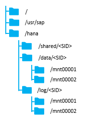
The sizing for SAP HANA file system volumes is based on the amount of memory equipped on the SAP HANA host.
Scale-Up Solutions
The recommended, minimum disk space requirements for SAP HANA TDI installations are:
| / (root) |
100 GB inclusive of space required for /usr/sap |
| /hana/shared |
1 × RAM or 1TB whichever is less |
| /hana/data |
1 × RAM |
| /hana/log |
512 GB |
Scale-Out Solutions
The recommended, minimum disk space requirements for SAP HANA TDI installations are:
| / (root) |
100 GB inclusive of space required for /usr/sap |
| /hana/shared |
1 × RAM for every 4 active HANA nodes |
| /hana/data |
1 × RAM for each active HANA node |
| /hana/log |
512 GB for each active HANA node |
The /hana/shared volume consists of installation binaries, as well as trace and configuration files and needs to be accessible to all hosts. The Hitachi HNAS 4060 platform provide the NFS share to the SAP HANA Scale-Out configuration.
Operating System
The minimum supported operating system versions for the second-Generation Intel ® Xeon® Scalable processors (Cascade Lake) and the SAP HANA platform are as follows:
· SUSE Linux Enterprise Server for SAP Applications 15 GA
· Red Hat Enterprise Linux for SAP HANA 7.6
High Availability
The infrastructure for any SAP HANA solution must not have a single point of failure. To support high availability, the hardware and software requirements are:
· External storage: Redundant data paths, dual controllers, and a RAID-based configuration
· Ethernet switches: Two or more independent switches
SAP HANA comes with an integrated high-availability function. If the SAP HANA system is configured with an additional stand-by host, a failed SAP HANA worker node will start on the stand-by node automatically. For automatic host failover the storage connector API must be properly configured during the installation of the SAP HANA platform.
Although not tested and validated in this design additional high-availability solutions like SAP HANA System Replication with Linux Cluster are available as well.
For detailed information from SAP refer to SAP HANA Administration Guide - High Availability for SAP HANA or SAP HANA Administration Guide – Configuring SAP HANA System Replication.
Physical Topology
The Cisco and Hitachi Adaptive Solutions for SAP HANA Tailored Data Center Integration provides an end-to-end architecture with Cisco Compute, Networking and Hitachi Storage that demonstrates support for multiple SAP HANA workloads with high availability and secure multi-tenancy. The architecture uses Cisco UCS Manager with combined Cisco UCS B-Series Servers and Cisco UCS Fabric Interconnects. The uplink from the Cisco UCS Fabric Interconnect is connected to Nexus 9336 switches with High Availability and Failover functionality. The storage traffic between the HANA servers and Hitachi Storage flows through Cisco UCS Fabric Interconnect and Cisco MDS Switching.
While the SAP HANA share volume resides on the Hitachi VSP for SAP HANA Scale-Up deployments a distributed SAP HANA Scale-Out configuration requires an additional HNAS to store the shared volume accessible for all hosts part of the SAP HANA Scale-Out configuration. Figure 10 shows the physical topology of the Cisco and Hitachi Adaptive Solutions for Converged Infrastructure SAP including the optional HNAS.
Figure 10 Physical Topology of the Cisco and Hitachi Adaptive Solutions for Converged Infrastructure SAP
The components of this integrated architecture are:
· Cisco Nexus 9336C-FX2 – 100 Gb capable, LAN connectivity to the Cisco UCS compute resources.
· Cisco UCS 6332-16UP Fabric Interconnect – Unified management of Cisco UCS compute, and the compute’s access to storage and networks.
· Cisco UCS B200 M5 – High powered, versatile blade server with two CPUs for SAP HANA.
· Cisco UCS B480 M5 – High powered, versatile blade server with four CPUs for SAP HANA.
· Cisco MDS 9706 – 32 Gbps Fiber Channel connectivity within the architecture, as well as interfacing to resources present in an existing data center.
· Hitachi VSP G370 – Mid-range, high performance storage subsystem with optional all-flash configuration.
· Hitachi NAS 4060 Platform – A network-attached storage solution used for file sharing, file server consolidation, data protection, and business-critical NAS workloads.
· Cisco UCS Manager – Management delivered through the Fabric Interconnect, providing stateless compute, and policy driven implementation of the servers managed by it.
Scale and Performance Consideration
Although this is the base validated design, each of the components can be scaled easily to support specific business requirements. Additional servers or even blade chassis can be deployed to increase compute capacity without additional Network components. Two Cisco UCS 6332-16UP Fabric interconnect with 16 x 16 Gbps FC unified ports and 24 x 40 GbE ports can support up to:
· 16 x Cisco UCS B-Series B480 M5 Server with 4 Blade Server Chassis and 1 x Hitachi Vantara VSP G370
· 32 x Cisco UCS B-Series B200 M5 Server with 4 Blade Server Chassis and 2 x Hitachi Vantara VSP G370
As per the certified and supported SAP HANA hardware directory 16 x SAP HANA nodes can be supported per Hitachi VSP F350 or G350 and F370 or G370.
Compute Connectivity
Each compute chassis in the design is connected to the managing fabric interconnect with at least two ports per IOM. Ethernet traffic from the upstream network and Fiber Channel frames coming from the VSP are converged within the fabric interconnect to be both Ethernet and Fiber Channel over Ethernet transmitted to the UCS servers through the IOM which are automatically configured as port channels with the specification of a Chassis/FEX Discovery Policy within UCSM.
These connections from the Cisco UCS 6332-16UP Fabric Interconnect to the 2304 IOM are shown in Figure 11.
Figure 11 Cisco UCS 6332-16UP Fabric Interconnect Connectivity to FEX 2304 IOM on Chassis 5108
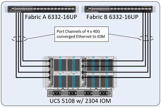
The 2304 IOM are shown with 4 x 40Gbps ports to deliver an aggregate of 320 Gbps to the chassis.
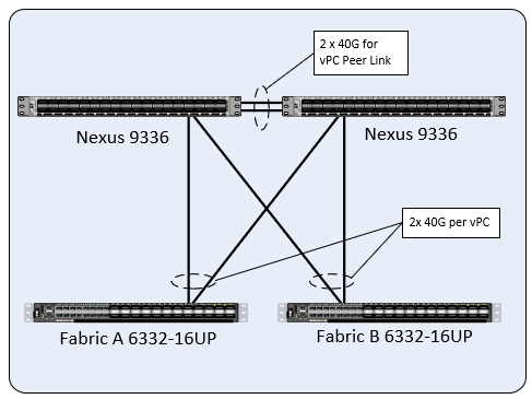
Network Connectivity
The network coming into each of the fabric interconnects is configured as a Port Channel to the respective fabric interconnects but is implemented as Virtual Port Channels (vPC) from the upstream Nexus switches. In the switching environment, the vPC provides the following benefits:
· Allows a single device to use a Port Channel across two upstream devices
· Eliminates Spanning Tree Protocol blocked ports and use all available uplink bandwidth
· Provides a loop-free topology
· Provides fast convergence if either one of the physical links or a device fails
· Helps ensure high availability of the network
The upstream network connecting to the Cisco UCS 6332-16UP Fabric Interconnects can utilize 10/40 ports to talk to the upstream Nexus switch. In this design, the 40G ports were used for the construction of the port channels that connected to the vPCs (Figure 12).
Figure 12 Cisco UCS 6454 Fabric Interconnect Uplink Connectivity to Nexus 9336-FX2
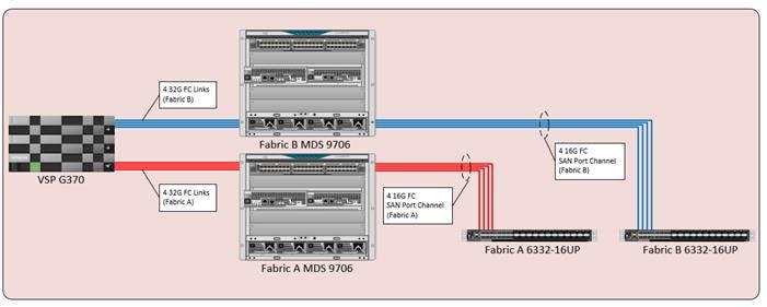
Storage Connectivity
The Hitachi VSP is connected to the respective fabric interconnects associated through the Cisco MDS 9706 switches. For the fabric interconnects, these are configured as SAN Port Channels, with N_Port ID Virtualization (NPIV) enabled on the MDS (Figure 13). This configuration allows:
· Increased aggregate bandwidth between the fabric interconnects and the MDS
· Load balancing between the links
· High availability in the result of a failure of one or more of the links
Figure 13 Storage Connectivity Overview for SAP HANA Scale-Up
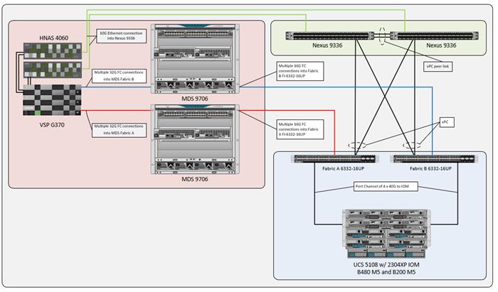
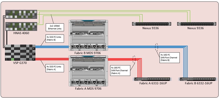
For SAP HANA Scale-Out configurations an additional Hitachi NAS is required to enable NFS shared storage. The HNAS attaches directly to the Hitachi VSP and connects to the respective fabric interconnects associated through the Cisco Nexus 9336 (Figure 14). This configuration allows:
· 10 GbE bandwidth between the Fabric Interconnects, Nexus and the Hitachi NAS
· Load balancing between the links
· High availability in the result of a failure of one link
Figure 14 Storage Connectivity Overview for SAP HANA Scale-Out
Hitachi VSP FC Port to Fabric Assignments
Each member of the VSP F series and G series is comprised of multiple controllers and channel board adapters (CHA or CHB) that control connectivity to the fiber channel fabrics. This allows for designing multiple layers of redundancy within the storage architecture, increasing availability and maintaining performance during a failure event. The VSP Fx00 model’s and Gx00 model’s CHA/CHBs each contain up to four individual fiber channel ports, allowing for redundant connections to each fabric in the Cisco UCS infrastructure.
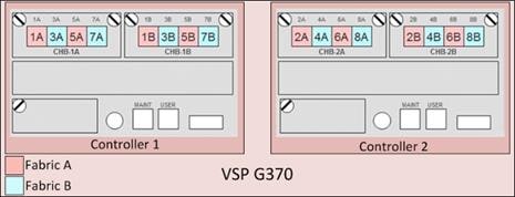
Hitachi VSP Fx00 series and Gx00 series systems have two controllers contained within the storage system. The port to fabric assignments for the VSP G370 used in this design are shown in Figure 15, illustrating multiple connections to each fabric and split evenly between VSP controllers and 32 Gb CHBs:
Figure 15 Hitachi VSP G370 Port Assignment
Hitachi VSP to NAS Platform 4060 Assignment
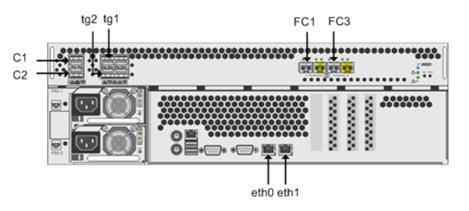
Each NAS Platform directly connects to the Virtual Storage Platform G370 target ports using two fibre channel cables from each NAS Platform 4060 node.
Port C1 and Port C2 are the cluster ports on NAS Platform 4060. To enable clustering, do the following:
· Connect Port C1 of first NAS Platform to Port C1 of the second NAS Platform.
· Connect Port C2 of first NAS Platform to Port C2 of the second NAS Platform.
Port tg1 and Port tg2 are 10 GbE ports. Link aggregate and connect these ports to the Cisco Nexus 9336.
Connect the 8Gb Fiber Channel Ports FC1 and FC3 of each NAS Platform 4060 node directly to the ports on Hitachi Virtual Storage Platform G370.
Connect Port eth0 on the NAS Platform to the management network on the Cisco Nexus 9336.
Figure 16 Hitachi NAS 4060 Port Assignment
Hitachi VSP LUN Presentation and Path Assignments
Following Hitachi’s best practices for SAP HANA TDI storage environments, four storage paths were assigned, comprised of two paths on each fabric. The storage is connected through four paths following the VSI design, nevertheless for SAP HANA TDI two storage paths are assigned and enough from a performance perspective. For each LUN, redundant paths considering controller and cluster failure were assigned.
MDS Zoning
Zoning within the MDS is configured for each SAP HANA Scale-Up host with single initiator multiple target zones, leveraging the Smart Zoning feature for greater efficiency. The design implements a simple, single VSAN layout per fabric within the MDS, however configuration of differing VSANs for greater security and tenancy are supported.
For SAP HANA Scale-Out hosts the zoning configuration within the MDS changes to a multiple initiator multiple target zone and each zone includes the initiator of all SAP HANA worker hosts to ensure successful failover of the SAP HANA standby host.
Initiator (Cisco UCS hosts) and targets (VSP controller ports) are set up with device aliases within the MDS for easier identification within zoning and flogi connectivity. Configuration of zoning and the zonesets containing them can be managed via CLI however it is also available for creation and editing with DCNM for a simpler administrative experience.
For more information about zoning and the Smart Zoning feature see the Storage Design Options section.
End-to-End Data Path
The architectures in this design is built around the implementation of fiber channel storage, includes 16 Gbps end to end FC for the Cisco UCS 6332-16UP to the VSP G370.
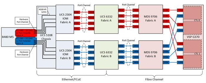
The architecture passage of traffic for the Cisco UCS 6332-16UP with the VSP G370 is shown in Figure 18:
· From the Cisco UCS B480 M5 server, equipped with a VIC 1340 adapter with Port Expander card, and VIC 1380 allowing for 40Gb on each side of the fabric (A/B) into the server.
· Pathing through 40Gb KR lanes of the Cisco UCS 5108 Chassis backplane into the Cisco UCS 2304 IOM (Fabric Extender).
· Connecting from each IOM to the Fabric Interconnect with pairs of 40 Gb uplinks automatically configured as port channels during chassis association, that carry the FC frames as FCoE along with the Ethernet traffic coming from the chassis blades.
· Continuing from the Cisco UCS 6332-16UP Fabric Interconnects into the Cisco MDS 9706 with multiple 16 Gbps FC ports configured as a port channel for increased aggregate bandwidth and link loss resiliency.
· Ending at the Hitachi VSP G370 fiber channel controller ports with dedicated F_Ports on the Cisco MDS 9706 for each N_Port WWPN of the VSP controller, with each fabric evenly split between the controllers, clusters, and channel adapters.
Figure 17 Storage Traffic Flow Between Cisco UCS B480-M5 Servers with VSP G370
Compute Design Options
Cisco UCS B-Series
Supporting up to 7.5 TB of memory in a half width blade format and 18 TB of memory in a full width blade format, these Cisco UCS servers are ideal for any SAP workloads. The configuration design of these servers includes:
· Diskless SAN boot – Persistent operating system installation, independent of the physical blade for true stateless computing.
· VIC 1340 with Port Expander and VIC 1380 provides four 40Gbps capable of up to 256 Express (PCIe) virtual adapters.
· SAP HANA 2.0 SPS 03 and newer supports various capacity ratios between Intel Optane DCPMMs and DIMMs.
Network Design Options
Management Connectivity
Out-of-band management is handled by an independent switch that could be one currently in place in the customer’s environment. Each physical device carries its management interface through this Out-of-band switch. In-band management is carried as a differing VLAN within the solution according to the SAP HANA Network requirements.
Out-of-band configuration for the components configured as in-band can be enabled, however this requires additional uplink ports on the 6332 Fabric Interconnects if the out-of-band management is kept on a separate out-of-band switch. A disjoint layer-2 configuration allows a complete separation of the management and data plane networks. This setup requires additional vNICs on each server, which are then associated with the management uplink ports.
Jumbo Frames
Jumbo frames are a standard recommendation across Cisco designs to help leverage the increased bandwidth availability of modern networks. To take advantage of the bandwidth optimization and reduced consumption of CPU resources gained through jumbo frames, they were configured at each network level to include the virtual switch and virtual NIC.
This optimization is relevant for VLANs that stay within the pod, and do not connect externally. Any VLANs that are extended outside of the pod should be left at the standard 1500 MTU to prevent drops from any connections or devices not configured to support a larger MTU.
Storage Design Options
Hitachi has certified its storage systems for the use as SAP HANA Enterprise Storage in SAP HANA TDI environments. This includes all members of the VSP family series and G series. Several design options are available with Hitachi VSP storage arrays to service different numbers of SAP HANA nodes. Choose from smaller, mid-range storage which can service 600,000 IOPS and 2.4PB of capacity to enterprise-class storage which can service up to 21 million IOPS and 69PB of capacity. Table 1 and Table 2 lists a comparison of the different models of VSP available within the family tested in this design.
Table 1 Comparison of VSP Fx00 Models and Gx00 Models
| VSP Model |
F350, F370, G350, G370 |
F700, G700 |
F900, G900 |
| Storage Class |
Mid-Range |
||
| Maximum IOPS |
600K to 1.2M IOPS 9 to 12GB/s bandwidth |
1.4M IOPS 24GB/s bandwidth |
2.4M IOPS 41GB/s bandwidth |
| Maximum Capacity |
2.8 to 4.3PB (SSD) 2.4 to 3.6PB (HDD) |
6PB (FMD) 13PB (SSD) 11.7PB (HDD) |
8.1PB (FMD) 17.3PB (SSD) 14PB (HDD) |
| Drive Types |
480GB, 1.9, 3.8, 7, 15TB SSD 600GB, 1.2, 2.4TB 10K HDD 6, 10TB 7.2K HDD |
3.5, 7, 14TB FMD 480GB, 1.9, 3.8, 7.6, 15TB SSD 600GB, 1.2, 2.4TB 10K HDD 6, 10TB 7.2K HDD |
3.5, 7, 14TB FMD 1.9, 3.8, 7.6, 15TB SSD 600GB, 1.2, 2.4TB 10K HDD 6, 10TB 7.2K HDD |
| Maximum FC Interfaces |
16x (16/32 Gbps FC) |
64x (16/32 Gbps FC) |
80x (16/32 Gbps FC) |
Table 2 Comparison of VSP 5000 Series
| VSP Model |
VSP 5100/5100H |
VSP 5500/5500H (1 pair nodes) |
VSP 5500/5500H (2 pair nodes) |
VSP 5500/5500H (3 pair nodes) |
| Storage Class |
Enterprise |
|||
| Maximum IOPS |
Up to 4.2M IOPS 25GB/s bandwidth |
Up to 21M IOPS Up to 149GB/s bandwidth
|
||
| Maximum Capacity |
23 PB (30TB SSD) |
23PB (30TB SSD) |
46 PB (30TB SSD) |
69 PB (30TB SSD) |
| Drive Types |
1.9, 3.8, 7.6 TB NVMe 7, 14 TB FMD 960GB, 3.8, 7.6, 15, 30 TB SSD 10, 14 TB 7.2K HDD |
1.9, 3.8, 7.6 TB NVMe 7, 14 TB FMD 960GB, 3.8, 7.6, 15, 30 TB SSD 10, 14 TB 7.2K HDD |
1.9, 3.8, 7.6 TB NVMe 7, 14 TB FMD 960GB, 3.8, 7.6, 15, 30 TB SSD 10, 14 TB 7.2K HDD |
1.9, 3.8, 7.6 TB NVMe 7, 14 TB FMD 960GB, 3.8, 7.6, 15, 30 TB SSD 10, 14 TB 7.2K HDD |
| Maximum FC Interfaces |
32x (16/32 Gbps FC) |
64x (16/32 Gbps FC) |
128x (16/32 Gbps FC) |
192x (16/32 Gbps FC) |
LUN Multiplicity per HBA and Different Pathing Options
This design implements Single Initiator-Multi Target (SI-MT) zoning in conjunction with single vHBAs per fabric on the Cisco UCS infrastructure. This means that each vHBA within UCS will see multiple paths on their respective fabric to each LUN. Using this design requires the use of Cisco Smart Zoning within the MDS switches.
Different pathing options including Single Initiator-Single Target (SI-ST) are supported, however it may reduce availability and performance especially during a component failure or upgrade scenario within the overall data path.
Zoning and Smart Zoning
For SAP HANA Scale-Up hosts zoning is set for single initiator (Cisco UCS host vHBA) with multiple targets (VSP controller ports) to optimize traffic intended to be specific to the host and the storage controller. Using single initiator/multiple target zoning provides reduced administrative overhead versus configuring single initiator/single target zoning, and results in the same SAN switching efficiency when configured with Smart Zoning.
For SAP HANA Scale-Out hosts zoning is set to multiple initiator with multiple targets to optimize traffic intended to be specific to the host or SAP HANA standby host and the storage controller.
Smart Zoning is configured on the MDS to allow for reduced TCAM (ternary content addressable memory) entries, which are fabric ACL entries of the MDS allowing traffic between targets and initiators. When calculating TCAMs used, two TCAM entries will be created for each connection of devices within the zone. Without Smart Zoning enabled for a zone, targets will have a pair of TCAMs established between each other, and all initiators will additionally have a pair of TCAMs established to other initiators in the zone as illustrated in Figure 18.
Figure 18 Traditional SAN Zoning
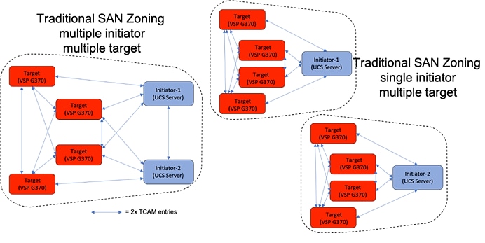
Using Smart Zoning, Targets and Initiators are identified, reducing TCAMs needed to only occur Target to Initiator within the zone as illustrated in Figure 19.
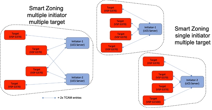
Large multiple initiator to multiple target zones can take on an exponential growth, especially without smart zoning enabled. Single initiator/single target zoning will produce the same amount of TCAM entries with or without Smart Zoning however it will match the TCAM entries used for any multiple target zoning method that is done with Smart Zoning.
Design Considerations
Cisco Nexus 9000 Series vPC Best Practices
The following Cisco Nexus 9000 design best practices and recommendations were used in this design.
vPC Peer Keepalive Link Considerations
· It is recommended to have a dedicated 1Gbps layer 3 links for vPC peer keepalive, followed by out-of-band management interface (mgmt0) and lastly, routing the peer keepalive link over an existing Layer3 infrastructure between the existing vPC peers.
· vPC peer keepalive link should not be routed over a vPC peer-link.
· The out-of-band management network is used as the vPC peer keepalive link in this design.
vPC Peer Link Considerations
· Only vPC VLANs are allowed on the vPC peer-links. For deployments that require non-vPC VLAN traffic to be exchanged between vPC peer switches, deploy a separate Layer 2 link for this traffic.
· Only required VLANs are allowed on the vPC peer links and member ports – prune all others to minimize internal resource consumption.
· Ports from different line cards should be used to provide redundancy for vPC peer links if using a modular switch model.
vPC General Considerations
· vPC peer switches deployed using same bridge-id and spanning tree VLAN priority by configuring the peer-switch command on both vPC peer switches. This feature improves convergence and allows peer switches to appear as a single spanning-tree root in the Layer 2 topology.
· vPC role priority specified on both Cisco Nexus peer switches. vPC role priority determines which switch will be primary and which one will be secondary. The device with the lower value will become the primary. By default, this value is 32677. Cisco recommends that the default be changed on both switches. Primary vPC devices are responsible for BPDU and ARP processing. Secondary vPC devices are responsible for shutting down member ports and VLAN interfaces when peer-links fail.
· vPC convergence time of 30s (default) was used to give routing protocol enough time to converge post-reboot. The default value can be changed using delay-restore <1-3600> and delay-restore interface-VLAN <1-3600> commands. If used, this value should be changed globally on both peer switches to meet the needs of your deployment.
· vPC peer switches enabled as peer-gateways using peer-gateway command on both devices. Peer-gateway allows a vPC switch to act as the active gateway for packets that are addressed to the router MAC address of the vPC peer allowing vPC peers to forward traffic.
· vPC auto-recovery enabled to provide a backup mechanism in the event of a vPC peer-link failure due to vPC primary peer device failure or if both switches reload but only one comes back up. This feature allows the one peer to assume the other is not functional and restore the vPC after a default delay of 240s. This needs to be enabled on both switches. The time to wait before a peer restores the vPC can be changed using the command: auto-recovery reload-delay <240-3600>.
· Cisco NX-OS can synchronize ARP tables between vPC peers using the vPC peer links. This is done using a reliable transport mechanism that the Cisco Fabric Services over Ethernet (CFSoE) protocol provides. For faster convergence of address tables between vPC peers, ip arp synchronize command was enabled on both peer devices in this design.
vPC Member Link Considerations
· LACP used for port channels in the vPC. LACP should be used when possible for graceful failover and protection from misconfigurations
· LACP mode active-active used on both sides of the port channels in the vPC. LACP active-active is recommended, followed by active-passive mode and manual or static bundling if the access device does not support LACP. Port-channel in mode active-active is preferred as it initiates more quickly than port-channel in mode active-passive.
· LACP graceful-convergence disabled on port-channels going to Cisco UCS FI. LACP graceful-convergence is ON by default and should be enabled when the downstream access switch is a Cisco Nexus device and disabled if it is not.
· Only required VLANs are allowed on the vPC peer links and member ports – prune all others to minimize internal resource consumption.
· Source-destination IP, L4 port and VLAN are used load-balancing hashing algorithm for port-channels. This improves fair usage of all member ports forming the port-channel. The default hashing algorithm is source-destination IP and L4 port.
vPC Spanning Tree Considerations
· The spanning tree priority was not modified. Peer-switch (part of vPC configuration) is enabled which allows both switches to act as root for the VLANs.
· Loopguard is disabled by default.
· BPDU guard and filtering are enabled by default.
· Bridge assurance is only enabled on the vPC Peer Link.
Storage Design Considerations
The following Hitachi VSP storage design best practices and recommendations were used in this design.
Hitachi Dynamic Provisioning Pools
Hitachi Storage Virtualization Operating System (SVOS) uses Hitachi Dynamic Provisioning (HDP) to provide wide striping and thin provisioning. Dynamic Provisioning provides one or more wide-striping pools across many RAID groups. Each pool has one or more dynamic provisioning virtual volumes (DP-VOLs) without initially allocating any physical space. Deploying Dynamic Provisioning avoids the routine issue of hot spots that occur on logical devices (LDEVs).
For SAP HANA TDI environments the following two dynamic provisioning pools created with Hitachi Dynamic Provisioning for the storage layout:
· OS_SH_DT_Pool for the following:
- OS volume
- SAP HANA data volume
- SAP HANA shared volume for SAP HANA Scale-Up nodes
· HANABIN_<SID>
· HNAS volumes for SAP HANA shared volumes in SAP HANA Scale-Out landscapes
· LOG_Pool for the following:
- SAP HANA log volume
The validated dynamic provisioning pool layout options with minimal disks and storage cache on Hitachi Virtual Storage Platform VSP F Series, VSP G Series and VSP 5000 Series storage ensures maximum utilization and optimization at a lower cost than other solutions. The SAP HANA node scalability for the VSP F series and G series is listed in Table 2, including the minimum number of RAID groups for SAS HDD and SSD drives.
Table 2 VSP F Series and G Series SAP HANA Node Scalability
| Storage |
Drive Type |
Maximum |
Minimal Parity Group |
|
| Data |
Log |
|||
| VSP G350 and VSP G370 |
SAS HDDs |
3 |
3 RAID-6 (14D+2P) |
1 RAID-6 (6D+2P) |
| VSP F350, VSP G350, VSP F370 and VSP G370 |
SSDs |
16 |
3 RAID-10 (2D+2D) |
3 RAID-10 (2D+2D) |
| VSP G700 |
SAS HDDs |
13 |
6 RAID-6 (14D+2P) |
3 RAID-6 (6D+2P) |
| VSP F700 and VSP G700 |
SSDs |
34 |
4 RAID-10 (2D+2D) |
5 RAID-10 (2D+2D) |
| VSP F900 and VSP G900 |
SSDs |
40 |
4 RAID-10 (2D+2D) |
4 RAID10 (2D+2D) |
| VSP 5100, VSP5100H |
SSDs |
37 |
3 RAID-6 (6D+2P) |
1 RAID-6 (6D+2P) |
| VSP 5500, VSP 5500H (1 pair nodes) |
SSDs |
14 RAID-10 (2D+2D) |
14 RAID-10 (2D+2D) |
|
| VSP 5500, VSP 5500H (2 pair nodes) |
SSDs |
148 |
28 RAID-10 (2D+2D) |
28 RAID-10 (2D+2D) |
| VSP 5500, VSP 5500H (3 pair nodes) |
SSDs |
222 |
42 RAID-10 (2D+2D) |
42 RAID-10 (2D+2D) |
Details about SAP HANA node scalability and configuration guidelines can be found in SAP HANA Tailored Data Center Integration on Hitachi Virtual Storage Platform G Series and VSP F Series with Hitachi Storage Virtualization Operating System Architecture Guide and SAP HANA TDI on VSP 5000 Series with Hitachi Storage Virtualization Operating System RF Reference Architecture.
Test Plan
Cisco and Hitachi validated and tested the three different solution scenarios:
· SAP HANA Scale-Up
· SAP HANA Scale-Up with Intel® Optane™ Data Center persistent memory modules
· SAP HANA Scale-Out
All solutions have been tested by Cisco and Hitachi Vantara providing an installation procedure for both, SUSE and Red Hat Linux, following best practices from Cisco, Hitachi Vantara and SAP. All SAP HANA TDI phase 5 requirements have been tested and passed performance metrics and high availability requirements, including:
· Cisco UCS Setup and Configuration
· VSP Setup and Configuration
· HNAS Setup and Configuration
· MDS Setup and Configuration
· Host Based SAN Boot
· Operating System Configuration for SAP HANA
· Installation and Configuration of SAP HANA 2.0 SPS03 Rev. 35
· Performance Tests using SAP’s Hardware Configuration Check Tool (HCMT)
Validated Hardware
Table 3 lists the hardware and software versions used during solution validation. It is important to note that Cisco, Hitachi Vantara, and SAP have interoperability matrixes that should be referenced to determine support. Links to this documentation are available in the Solution References section.
Table 3 Hardware and Software Versions used in this Solution
| Component |
Software |
|
| Network |
Nexus 9336C-FX2 |
7.0(3)I7(5a) |
| MDS 9706 (DS-X97-SF1-K9 & DS-X9648-1536K9) |
8.3(1) |
|
| Compute |
Cisco UCS Fabric Interconnect 6454 |
4.0(4b) |
| Cisco UCS 2304 IOM |
4.0(4b) |
|
| Cisco UCS B200 M5 |
4.0(4b) |
|
| Cisco UCS B480 M5 |
4.0(4b) |
|
| Operating System |
SUSE Linux Operating System |
SLES for SAP Applications 15 GA |
| Red Hat Operating System |
RHEL for SAP HANA 7.6 |
|
| Storage |
Hitachi VSP G370 |
88-02-03-60/00 |
| Hitachi NAS Platform 4060 |
13.5.5336.06 |
|
The Cisco and Hitachi Adaptive Solutions for SAP HANA Tailored Data Center Integration is built close-partnered between Cisco and Hitachi to support SAP HANA workloads in a TDI environment. It is validated for both SUSE Linux Enterprise Server and Red Hat Enterprise Linux operating systems.
The solution utilizes Cisco UCS M5 Blade Servers, Cisco Fabric Interconnects, Cisco Nexus 9000 switches, Cisco MDS switches, fiber channel-attached Hitachi VSP storage for SAP HANA Scale-Up deployments. SAP HANA Scale-Out deployments require an additional network attached Hitachi NAS storage platform to host the SAP HANA shared volume. Both variants with and without Intel® Optane™ Data Center persistent memory modules have been validated for SAP HANA Scale-Up deployments. The reference design is designed and validated using compute, network and storage best practices for high performance, scalability, and resiliency throughout the architecture.
References
Scaramella, J., Rutten, P., & Marden, M. (2016, March). IDC White Paper | Business Value of Improved Performance and Agility with Cisco HyperFlex. Retrieved from www.idc.com: https://hosteddocs.ittoolbox.com/IDC-The%20Business%20Value%20of%20Cisco%20UCS%20Integrated%20Infrastructure%20Solutions.pdf
Products and Solutions
Cisco Unified Computing System:
http://www.cisco.com/en/US/products/ps10265/index.html
Cisco UCS 6300 Fabric Interconnect Data Sheet:
https://www.cisco.com/c/en/us/products/collateral/servers-unified-computing/ucs-6300-series-fabric-interconnects/datasheet-c78-736682.html
Cisco UCS 5100 Series Blade Server Chassis:
http://www.cisco.com/en/US/products/ps10279/index.html
Cisco UCS 2300 Series Fabric Extenders:
Cisco UCS B-Series Blade Servers:
http://www.cisco.com/en/US/partner/products/ps10280/index.html
Cisco UCS Adapters:
http://www.cisco.com/en/US/products/ps10277/prod_module_series_home.html
Cisco UCS Manager:
http://www.cisco.com/en/US/products/ps10281/index.html
Cisco Intersight:
https://www.cisco.com/c/en/us/products/servers-unified-computing/intersight/index.html
Cisco Nexus 9000 Series Switches:
http://www.cisco.com/c/en/us/products/switches/nexus-9000-series-switches/index.html
Cisco MDS 9000 Series Multilayer Switches:
Hitachi Virtual Storage Platform F Series:
Hitachi Virtual Storage Platform G Series:
Hitachi VSP 5000 Series:
Hitachi NAS Platform:
https://www.hitachivantara.com/en-us/products/storage/network-attached-storage-platform.html
SAP HANA Tailored Data Center Integration with Hitachi VSP F/G Storage Systems and SVOS RF:
Intel Optane DC Persistent Memory and SAP HANA Platform Configuration:
SAP HANA
SAP HANA Platform on SAP Help Portal:
https://help.sap.com/viewer/p/SAP_HANA_PLATFORM
SAP HANA Tailored Data Center Integration Overview:
https://www.sap.com/documents/2017/09/e6519450-d47c-0010-82c7-eda71af511fa.html
SAP HANA Tailored Data Center Integration - Storage Requirements:
https://www.sap.com/documents/2015/03/74cdb554-5a7c-0010-82c7-eda71af511fa.html
SAP HANA Network Requirements
https://www.sap.com/documents/2016/08/1cd2c2fb-807c-0010-82c7-eda71af511fa.html and Supported SAP
SAP Note 190823 – SAP HANA Storage Connector API
https://launchpad.support.sap.com/#/notes/1900823
HANA Hardware
https://www.sap.com/dmc/exp/2014-09-02-hana-hardware/enEN/index.html
Interoperability Matrixes
Cisco UCS Hardware Compatibility Matrix:
https://ucshcltool.cloudapps.cisco.com/public/
Cisco Nexus and MDS Interoperability Matrix:
Hitachi Vantara Interoperability:
https://support.hitachivantara.com/en_us/interoperability.html
Joerg Wolters, Technical Marketing Engineer, Cisco Systems GmbH
Joerg is a Technical Marketing Engineer part of the Cisco UCS Solutions and Performance Group. Joerg has over six years of experience with SAP HANA on Cisco UCS platform. Joerg led the Cisco Solution Support for SAP HANA during the past five years. Currently, his focus is on developing and validating infrastructure best practices for SAP applications on Cisco UCS Servers, Cisco Nexus products and Storage technologies.
Acknowledgements
For their support and contribution to the design, validation, and creation of this Cisco Validated Design, the authors would like to thank:
· Shailendra Mruthunjaya, Cisco Systems, Inc.
· Dr. Stephan Kreitz, Hitachi Vantara
· Maximilian Weiß, Hitachi Vantara
 Feedback