Cisco ME 3400E Ethernet Access Switch Hardware Installation Guide
Bias-Free Language
The documentation set for this product strives to use bias-free language. For the purposes of this documentation set, bias-free is defined as language that does not imply discrimination based on age, disability, gender, racial identity, ethnic identity, sexual orientation, socioeconomic status, and intersectionality. Exceptions may be present in the documentation due to language that is hardcoded in the user interfaces of the product software, language used based on RFP documentation, or language that is used by a referenced third-party product. Learn more about how Cisco is using Inclusive Language.
- Updated:
- March 21, 2015
Chapter: Connecting the AC and DC Power Supply Modules
Installing and Removing AC- and DC-Power-Supply Modules
This chapter provides the installation and removal instructions for the AC- and DC-power-supply modules for the Cisco ME 3400E-24TS-M and the Cisco ME 3400EG-12CS-M. Your switch ships with at least one power-supply module installed, either AC or DC, depending on your order. The power-supply modules are field-replaceable units (FRUs).
For translations of the safety warnings in this chapter, see the Regulatory Compliance and Safety Information for the Cisco ME 3400E Switch on the documentation CD and also on Cisco.com.
•![]() Power-Supply Module Installation
Power-Supply Module Installation
Product Overview
This section gives an overview of the AC- and DC-power-supply modules.
•![]() Power-Supply Module Description
Power-Supply Module Description
Power-Supply Module Description
The 80-W AC-power-supply module is an autoranging unit that supports input voltages between 85 and 264 VAC. The DC-power-supply module has dual input feeds (A and B) and supports input voltages between -36 to -72 VDC for telecom applications and +18 to +36 VDC for industrial applications.
The AC-power-supply modules ship with a power cord to connect to an AC-power outlet. The DC-power-supply module ships with a terminal block to be wired for DC-power outlet connections.
Each power supply is cooled by internal fans. For maximum efficiency, at least two of the four fans should be operational in a warm environment. A fan failure triggers an alarm. When a fan fails, replace the power supply immediately.
You can order the generic AC-power cord (part number CAB-AC).
Handle-Side Description
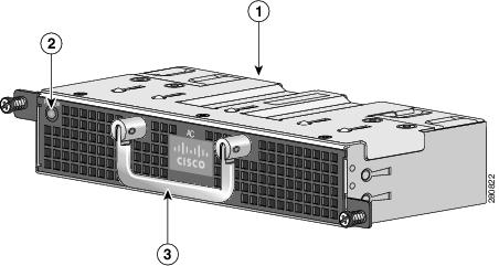
Figure 3-1 80-W AC-Power-Supply Module Handle Side
|
|
Power-supply module |
|
Extraction handle |
|
|
PSU OK LED |
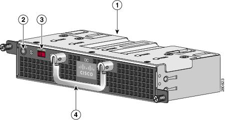
Figure 3-2 80-W DC-Power-Supply Module Handle Side
|
|
Power-supply module |
|
DC-power-supply voltage switch |
|
|
PSU OK LED |
|
Extraction handle |
Figure 3-3 shows the DC-power-supply module PSU OK LED and the DC-voltage selector.
•![]() For telecom applications (-36 to -72 VDC), set the DC-voltage selector to -48 VDC.
For telecom applications (-36 to -72 VDC), set the DC-voltage selector to -48 VDC.
•![]() For industrial applications (+18 to +36 VDC), set the DC-voltage selector to +24 VDC.
For industrial applications (+18 to +36 VDC), set the DC-voltage selector to +24 VDC.
Figure 3-3 DC-Voltage Selector

The PSU OK LED on the AC-power-supply module looks the same as the one in Figure 3-3. The AC-power-supply module does not have a voltage selector.
Connector-Side Description
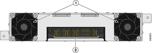
Figure 3-4 shows the connector side of the power-supply module, which connects to the switch rear panel through its power-supply slot.
Figure 3-4 Power-Supply Module Connector Side
|
|
Fans |
|
Connector pins |
Power-Supply Module Installation
•![]() Installing an AC-Power-Supply Module
Installing an AC-Power-Supply Module
•![]() Installing a DC-Power-Supply Module
Installing a DC-Power-Supply Module
Tools and Equipment
Obtain these necessary tools and equipment:
•![]() Ratcheting torque screwdriver with a number-2 Phillips head that exerts up to 15 inch-pounds (in-lb) of pressure.
Ratcheting torque screwdriver with a number-2 Phillips head that exerts up to 15 inch-pounds (in-lb) of pressure.
•![]() Power-supply power-cord retainer in the switch accessory kit.
Power-supply power-cord retainer in the switch accessory kit.
Installation Guidelines
Observe these guidelines when you install a power-supply module:
•![]() Do not force the power-supply module into the slot. This can damage the pins on the switch if they are not aligned with the unit.
Do not force the power-supply module into the slot. This can damage the pins on the switch if they are not aligned with the unit.
•![]() A power-supply module that is only partially connected to the switch can disrupt the system operation.
A power-supply module that is only partially connected to the switch can disrupt the system operation.
•![]() Turn off switch power before you install the module.
Turn off switch power before you install the module.
•![]() Verify that you are using the correct power cord.
Verify that you are using the correct power cord.
 |
Warning |
|
Warning |
|
Warning |

Figure 3-5 Blank Cover Installed on the Power-Supply Slot
Installing an AC-Power-Supply Module
This procedure is for installing an AC-power-supply module in the PSU 1 power-supply slot. Repeat these steps to install a power-supply module in the PSU 2 power-supply slot.

Note ![]() If you operate the switch with two power supplies, enter the power-supply dual global configuration command to configure the switch to send a message when one power supply is missing.
If you operate the switch with two power supplies, enter the power-supply dual global configuration command to configure the switch to send a message when one power supply is missing.
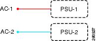
Each AC-power input is dedicated to one power-supply module (PSU 1 or PSU 2). One AC-power input does not power on both power-supply modules at the same time (Figure 3-6):
Figure 3-6 AC-Power-Supply Diagram
To install an AC-powered power-supply module, follow these steps:
Step 1 ![]() Verify that the power from the power source is off.
Verify that the power from the power source is off.
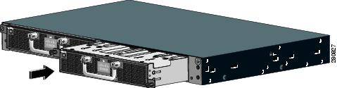
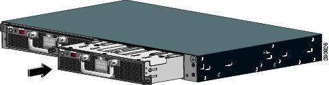
Step 2 ![]() Insert the new power-supply module in the power-supply slot, and gently push it into the slot (see Figure 3-7). When correctly inserted, the power-supply module is flush with the switch rear panel.
Insert the new power-supply module in the power-supply slot, and gently push it into the slot (see Figure 3-7). When correctly inserted, the power-supply module is flush with the switch rear panel.
Figure 3-7 Inserting an AC-Power-Supply Module in a Switch
Step 3 ![]() Align the two captive screws with the screw holes in the panel. Use a ratcheting torque screwdriver to torque each screw to 10 in-lb.
Align the two captive screws with the screw holes in the panel. Use a ratcheting torque screwdriver to torque each screw to 10 in-lb.
Step 4 ![]() Connect the AC-power cord to the front panel power supply and to an AC-power outlet.
Connect the AC-power cord to the front panel power supply and to an AC-power outlet.
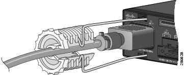
Step 5 ![]() (Optional) Snap the AC-power-cord retainer into place, and attach the plastic bushing to secure the power cord (see Figure 3-8).
(Optional) Snap the AC-power-cord retainer into place, and attach the plastic bushing to secure the power cord (see Figure 3-8).
Figure 3-8 AC-Power Supply and Power-Cord Retainer in a Switch
Step 6 ![]() Turn on the power at the power source.
Turn on the power at the power source.
Step 7 ![]() Confirm that both the AC 1 LED and the PSU 1 LED are green. (If you can access the switch rear panel, verify that the PSU OK LED is green.) See Table 3-2 for a description of the power-supply module LEDs. See Table 1-4 and Table 1-5 for system and power-supply LED descriptions.
Confirm that both the AC 1 LED and the PSU 1 LED are green. (If you can access the switch rear panel, verify that the PSU OK LED is green.) See Table 3-2 for a description of the power-supply module LEDs. See Table 1-4 and Table 1-5 for system and power-supply LED descriptions.
Removing AC-Power-Supply Modules
Step 1 ![]() Turn off the power at its source.
Turn off the power at its source.
Step 2 ![]() Detach the power-cord retainer and the plastic bushing from the power cord.
Detach the power-cord retainer and the plastic bushing from the power cord.
Step 3 ![]() Remove the power cord from the power connector.
Remove the power cord from the power connector.
Step 4 ![]() Use a Phillips screwdriver to loosen the two captive screws that secure the power-supply module to the chassis. One screw is on the lower right of the module, and the other screw is on the upper left of the module.
Use a Phillips screwdriver to loosen the two captive screws that secure the power-supply module to the chassis. One screw is on the lower right of the module, and the other screw is on the upper left of the module.
Step 5 ![]() Remove the power-supply module from the power slot by pulling on the extraction handle.
Remove the power-supply module from the power slot by pulling on the extraction handle.
Installing a DC-Power-Supply Module
This procedure is for installing an DC-power-supply module into the PSU 1 power-supply slot. Repeat these steps to install a power-supply module in the PSU 2 power-supply slot.
To connect the switch to a DC-input power source, follow these steps:
3. ![]() Installing the DC-Power-Supply Module in the Switch
Installing the DC-Power-Supply Module in the Switch
4. ![]() Wiring the DC-Input Power Source
Wiring the DC-Input Power Source
Note ![]() The grounding architecture of this product is DC-isolated (DC-I).
The grounding architecture of this product is DC-isolated (DC-I).
Note ![]() We recommend that you use 18 AWG copper wiring for Network Equipment Building Systems (NEBS) installation. This guideline follows the standard guidelines for DC-power wiring in the central office.
We recommend that you use 18 AWG copper wiring for Network Equipment Building Systems (NEBS) installation. This guideline follows the standard guidelines for DC-power wiring in the central office.
Note ![]() You can use the grounding lug to attach a wrist strap for ESD protection during servicing.
You can use the grounding lug to attach a wrist strap for ESD protection during servicing.
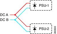
Each DC-power input (A ± and B ±) is connected to both power-supply module 1 (PSU 1) and power-supply module 2 (PSU 2). The power-supply modules cannot be powered independently. DC inputs and returns are diode-isolated (Figure 3-9).
Figure 3-9 DC-Power-Supply Diagram
Preparing for Installation
Obtain these necessary tools and equipment:
•![]() Ratcheting torque screwdriver with a number-2 and a number-1 Phillips head that exerts up to 15 inch-pounds (in-lb).
Ratcheting torque screwdriver with a number-2 and a number-1 Phillips head that exerts up to 15 inch-pounds (in-lb).
•![]() Panduit crimping tool with optional controlled-cycle mechanism (model CT-720, CT-920, CT-920CH, CT-930, or CT-940CH).
Panduit crimping tool with optional controlled-cycle mechanism (model CT-720, CT-920, CT-920CH, CT-930, or CT-940CH).
•![]() Wire-stripping tools.
Wire-stripping tools.
•![]() Copper ground wire (insulated or noninsulated) for the ground connection.
Copper ground wire (insulated or noninsulated) for the ground connection.
•![]() Dual-hole, right-angle ground lug from the switch accessory kit (for the Cisco ME 3400E-24TS-M and the Cisco ME 3400EG-12CS-M).
Dual-hole, right-angle ground lug from the switch accessory kit (for the Cisco ME 3400E-24TS-M and the Cisco ME 3400EG-12CS-M).
•![]() Dual-hole ground lug from the switch accessory kit (for the Cisco ME 3400EG-2CS-A).
Dual-hole ground lug from the switch accessory kit (for the Cisco ME 3400EG-2CS-A).
•![]() Four leads of 16-gauge copper wire.
Four leads of 16-gauge copper wire.
•![]() Four-position DC-terminal-block connector from the accessory kit.
Four-position DC-terminal-block connector from the accessory kit.
To order a spare or replacement DC-connector, use this source:
•![]() Amphenol PCD: ELFF0422S1 (Cisco part number 29-6063-0).
Amphenol PCD: ELFF0422S1 (Cisco part number 29-6063-0).
Grounding the Switch
To make sure that the equipment is reliably connected to earth ground, follow the grounding procedure instructions and observe these warnings:
|
Warning |
Follow these steps to install either a single-ground lug or a dual-ground lug on the switch. Make sure to follow any grounding requirements at your site.
Step 1 ![]() Locate the ground adaptor and the dual-hole lug that ships with the switch.
Locate the ground adaptor and the dual-hole lug that ships with the switch.
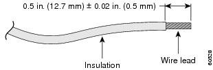
Step 2 ![]() If your ground wire is insulated, use a wire stripping tool to strip the 12-gauge or 6-gauge ground wire to 0.5 inch (12.7 mm) ± 0.02 inch (0.5 mm) (Figure 3-10). Use 12-gauge copper ground wire for the single-ground connection. Use 6-gauge copper ground wire for the ground connection.
If your ground wire is insulated, use a wire stripping tool to strip the 12-gauge or 6-gauge ground wire to 0.5 inch (12.7 mm) ± 0.02 inch (0.5 mm) (Figure 3-10). Use 12-gauge copper ground wire for the single-ground connection. Use 6-gauge copper ground wire for the ground connection.
Figure 3-10 Stripping the Ground Wire
Step 3 ![]() Slide the open end of the ground lug over the exposed area of the wire.
Slide the open end of the ground lug over the exposed area of the wire.
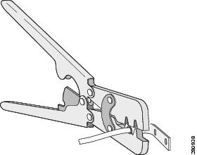
Step 4 ![]() Use a Panduit crimping tool to crimp the ground lug to the wire (see Figure 3-11).
Use a Panduit crimping tool to crimp the ground lug to the wire (see Figure 3-11).
Figure 3-11 Crimping the Ground Lug
Step 5 ![]() Remove the ground screw from the switch rear panel.
Remove the ground screw from the switch rear panel.
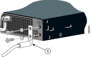
Step 6 ![]() Attach the dual-hole lug and the wire assembly to the adaptor with the supplied nuts (Figure 3-12).
Attach the dual-hole lug and the wire assembly to the adaptor with the supplied nuts (Figure 3-12).
Step 7 ![]() Use a ratcheting torque screwdriver to torque the ground-lug screws to 60 in-lb.
Use a ratcheting torque screwdriver to torque the ground-lug screws to 60 in-lb.
Step 8 ![]() Connect the other end of the grounding wire to an appropriate grounding point at your site or to the rack.
Connect the other end of the grounding wire to an appropriate grounding point at your site or to the rack.
Figure 3-12 Attaching the Ground Lug and Wire Assembly
|
|
Dual-hole ground lug |
Installing the DC-Power-Supply Module in the Switch
Step 1 ![]() Verify that power is off at the DC circuits. To ensure that power is removed from the DC circuits, locate the circuit breakers for the DC circuits, switch the circuit breakers to the OFF position, and tape the circuit-breaker switches in the OFF position.
Verify that power is off at the DC circuits. To ensure that power is removed from the DC circuits, locate the circuit breakers for the DC circuits, switch the circuit breakers to the OFF position, and tape the circuit-breaker switches in the OFF position.
Step 2 ![]() Insert the new power-supply module into the power-supply slot, and gently push it into the slot (see Figure 3-13). When correctly inserted, the power supply is flush with the switch rear panel.
Insert the new power-supply module into the power-supply slot, and gently push it into the slot (see Figure 3-13). When correctly inserted, the power supply is flush with the switch rear panel.
Figure 3-13 Inserting a DC-Power-Supply Module
Step 3 ![]() Align the two captive screws with the screw holes. Use a ratcheting torque screwdriver to torque each screw to 7 in-lb.
Align the two captive screws with the screw holes. Use a ratcheting torque screwdriver to torque each screw to 7 in-lb.
Step 4 ![]() Set the DC-voltage selector (see Figure 3-14):
Set the DC-voltage selector (see Figure 3-14):
•![]() For telecom applications (-36 to -72 VDC), set the DC-voltage selector to -48 VDC.
For telecom applications (-36 to -72 VDC), set the DC-voltage selector to -48 VDC.
•![]() For industrial applications (+18 to +36 VDC), set the DC-voltage selector to +24 VDC.
For industrial applications (+18 to +36 VDC), set the DC-voltage selector to +24 VDC.
Figure 3-14 DC-Voltage Selector
Step 5 ![]() Connect the input power as described in the "Wiring the DC-Input Power Source" section.
Connect the input power as described in the "Wiring the DC-Input Power Source" section.
Wiring the DC-Input Power Source
Before you wire the DC-input power source, review the warnings in this section and this information:
|
Warning 10 A Statement 1005 |
|
Warning Statement 1022 |
|
Warning Statement 103 |
Step 1 ![]() To ensure that all power is OFF, locate the circuit breaker on the panel board that services the DC circuit, switch the circuit breaker to the OFF position, and tape the switch handle of the circuit breaker in the OFF position.
To ensure that all power is OFF, locate the circuit breaker on the panel board that services the DC circuit, switch the circuit breaker to the OFF position, and tape the switch handle of the circuit breaker in the OFF position.
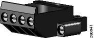
Step 2 ![]() Locate the terminal block plug (see Figure 3-15).
Locate the terminal block plug (see Figure 3-15).
Figure 3-15 Terminal Block Plug
Step 3 ![]() Identify the positive and negative feed positions for the terminal block connection. The wiring sequence is positive to positive and negative to negative for both the A and the B feed wires.
Identify the positive and negative feed positions for the terminal block connection. The wiring sequence is positive to positive and negative to negative for both the A and the B feed wires.
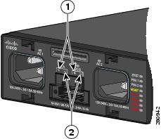
The switch front panel shows the positive and negative positions for both the A and B feed wires. (See Figure 3-16.)
Figure 3-16 Positive and Negative Positions
|
|
Positive position |
|
Negative position |
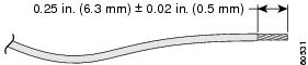
Step 4 ![]() Use an 18-gauge (1 mm) wire-stripping tool to strip each of the four wires coming from the DC-input power source to 0.27 inch (6.6 mm) ± 0.02 inch (0.5 mm). Do not strip more than 0.29 inch (7.4 mm) of insulation from the wire. Stripping more than the recommended amount of wire can leave exposed wire from the terminal block plug after installation.
Use an 18-gauge (1 mm) wire-stripping tool to strip each of the four wires coming from the DC-input power source to 0.27 inch (6.6 mm) ± 0.02 inch (0.5 mm). Do not strip more than 0.29 inch (7.4 mm) of insulation from the wire. Stripping more than the recommended amount of wire can leave exposed wire from the terminal block plug after installation.
Figure 3-17 Stripping the DC-Input Power Source Wire
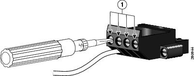
Step 5 ![]() Insert the exposed wire of one of the four DC-input power source wires into the terminal block plug.
Insert the exposed wire of one of the four DC-input power source wires into the terminal block plug.
Make sure that you cannot see any wire lead. Only wire with insulation should extend from the terminal block.
Figure 3-18 Inserting Wires in the Terminal Block Plug
|
|
Return (positive) Feed A |
|
Return (positive) Feed B |
|
|
Supply (negative) Feed A |
|
Supply (negative) Feed B |
Step 6 ![]() Use a ratcheting torque screwdriver to torque the terminal block captive screw (above the installed wire lead) to 4.5 in-lb (see Figure 3-19).
Use a ratcheting torque screwdriver to torque the terminal block captive screw (above the installed wire lead) to 4.5 in-lb (see Figure 3-19).
Figure 3-19 Torquing the Terminal-Block Captive Screws
|
|
Torque to 4.5 in-lb |
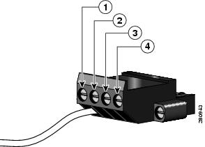
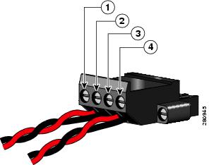
Step 7 ![]() Repeat Step 5 and Step 6 for the remaining three DC-input power source wires. Figure 3-20 shows the completed wiring of a terminal block plug.
Repeat Step 5 and Step 6 for the remaining three DC-input power source wires. Figure 3-20 shows the completed wiring of a terminal block plug.
Figure 3-20 Completed Wiring of Terminal Block Plug for Telecom Applications
|
|
Return (positive) Feed A |
|
Return (positive) Feed B |
|
|
Supply (negative) Feed A |
|
Supply (negative) Feed B |
Step 8 ![]() Insert the terminal block plug in the terminal block header on the switch front panel. (See Figure 3-21).
Insert the terminal block plug in the terminal block header on the switch front panel. (See Figure 3-21).
Figure 3-21 Inserting the Terminal Block in the Block Header
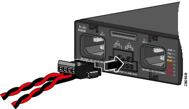
Step 9 ![]() Secure the terminal block by using the screws on the far left and right of the terminal block.
Secure the terminal block by using the screws on the far left and right of the terminal block.
Step 10 ![]() Remove the tape from the circuit-breaker switch handle, and move the circuit-breaker handle to the ON position.
Remove the tape from the circuit-breaker switch handle, and move the circuit-breaker handle to the ON position.
Step 11 ![]() Move the DC-power source circuit-breaker handles to the ON position.
Move the DC-power source circuit-breaker handles to the ON position.
Step 12 ![]() Confirm that both the DCA LED and the PSU 1 LEDs are green. (If you can access the switch rear panel, verify that the power-supply module PSU OK LED is green.) See Table 3-2 for a description of the power-supply module LEDs. See Table 1-4 and Table 1-6 for the status and DC-power-supply LED descriptions.
Confirm that both the DCA LED and the PSU 1 LEDs are green. (If you can access the switch rear panel, verify that the power-supply module PSU OK LED is green.) See Table 3-2 for a description of the power-supply module LEDs. See Table 1-4 and Table 1-6 for the status and DC-power-supply LED descriptions.
Figure 3-22 shows the front of the switch when DC-power-supply modules are installed. The DC A and DC B LEDs are green when the respective feeds are active.
Figure 3-22 DC-Power Terminal Block With Two Feeds
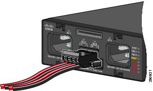
Note ![]() This illustration shows two sets of feeds installed. You can install one set of feeds, A or B.
This illustration shows two sets of feeds installed. You can install one set of feeds, A or B.
See the "Power Supply Settings" section for information on how to configure the power supply settings.
Removing the DC-Power-Supply Module
Step 1 ![]() Turn off power at the DC circuits. To ensure that power is removed from the DC circuits, locate the circuit breakers for the DC circuits, switch the circuit breakers to the OFF position, and tape the circuit-breaker switches in the OFF position.
Turn off power at the DC circuits. To ensure that power is removed from the DC circuits, locate the circuit breakers for the DC circuits, switch the circuit breakers to the OFF position, and tape the circuit-breaker switches in the OFF position.
Step 2 ![]() Use a number-2 Phillips screwdriver to remove the plastic safety cover from the power-supply terminal blocks.
Use a number-2 Phillips screwdriver to remove the plastic safety cover from the power-supply terminal blocks.
Step 3 ![]() Use a number-1 Phillips screwdriver to remove the DC-input power wires from the power terminals.
Use a number-1 Phillips screwdriver to remove the DC-input power wires from the power terminals.
Step 4 ![]() Use a Phillips screwdriver to loosen the two captive screws at the lower edge that secure the power-supply module to the switch chassis.
Use a Phillips screwdriver to loosen the two captive screws at the lower edge that secure the power-supply module to the switch chassis.
Step 5 ![]() Remove the power-supply module from the power slot by pulling on the extraction handle.
Remove the power-supply module from the power slot by pulling on the extraction handle.
Power Supply Settings
•![]() Use the no power-supply global configuration command (the default) when installing one power-supply module. The switch does not send an alarm when the second power-supply module is missing.
Use the no power-supply global configuration command (the default) when installing one power-supply module. The switch does not send an alarm when the second power-supply module is missing.
•![]() Use the power-supply dual global configuration command when installing two power-supply modules. When both are operating properly, all applicable LEDs are green, and the switch does not send an alarm. If a power-supply module is missing, the switch sends an alarm. An error message appears and the appropriate power-supply LED turns red.
Use the power-supply dual global configuration command when installing two power-supply modules. When both are operating properly, all applicable LEDs are green, and the switch does not send an alarm. If a power-supply module is missing, the switch sends an alarm. An error message appears and the appropriate power-supply LED turns red.
•![]() Use the power-supply dual dc-feed global configuration command when two DC-input feeds are connected to the DC-power source. When both are operating properly, all the applicable LEDs are green and the switch does not send an alarm. If only one DC-input feed is connected, and there is at least one DC-power-supply module installed, the switch sends an alarm. An error message appears and the DC-power-supply LED for the missing DC-input feed turns amber. The LED for the connected DC-input feed turns green.
Use the power-supply dual dc-feed global configuration command when two DC-input feeds are connected to the DC-power source. When both are operating properly, all the applicable LEDs are green and the switch does not send an alarm. If only one DC-input feed is connected, and there is at least one DC-power-supply module installed, the switch sends an alarm. An error message appears and the DC-power-supply LED for the missing DC-input feed turns amber. The LED for the connected DC-input feed turns green.
•![]() Use the no power-supply dual dc-feed global configuration command when only one DC-input feed is connected. The switch does not send an alarm when the second DC-input feed is not connected.
Use the no power-supply dual dc-feed global configuration command when only one DC-input feed is connected. The switch does not send an alarm when the second DC-input feed is not connected.
See the switch software configuration guide and switch command reference for more details on these settings.
 Feedback