Configuring Horizontal Stacking
This document describes how to configure horizontal stacking on the IE 5000 switch.
Information About Horizontal Stacking
 Note |
The documentation set for this product strives to use bias-free language. For purposes of this documentation set, bias-free is defined as language that does not imply discrimination based on age, disability, gender, racial identity, ethnic identity, sexual orientation, socioeconomic status, and intersectionality. Exceptions may be present in the documentation due to language that is hardcoded in the user interfaces of the product software, language used based on standards documentation, or language that is used by a referenced third-party product. |
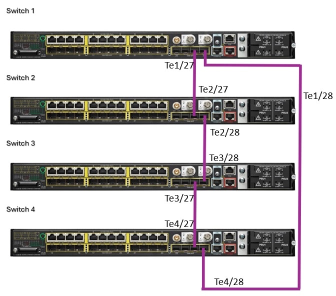
Horizontal stacking, also referred to as long-reach stacking, allows you to stack between two to four IE 5000 switches that are far apart, potentially up to a few kilometers. Horizontal stacking works by converting two of the TenGigabit Ethernet ports on the front of the IE5000 into special stacking ports. The special stacking ports interconnect the switches, forming the communication backbone of the stack. Switches can be stacked across multiple cell/area zone locations, and even across multiple buildings in a customer environment. Horizontal stacking provides resiliency and optimal convergence in industrial Ethernet networks.
In a stack, all switches appear as a single logical switch with a single IP address. Benefits of stacking include ease of management due to fewer stand-alone devices, increased port density, increased redundancy, and flexibility to add devices as required. All manageable entities (for example, Ethernet interfaces and VLANs) on all physical switches can be configured and managed from the logical switch. In a Layer 2 network, the logical switch appears as a single spanning-tree entity.
Horizontal stacking is supported on IE 5000 switch model IE-5000-12S12P-10G. Any one or two of the four 10 Gigabit Ethernet uplink ports on this switch can connect to another IE-5000-12S12P-10G switch in a different location to form a stack. You configure the 10G uplink ports as stack ports using the Command Line Interface (CLI). With two stack ports configured, the physical members of the stack form a ring, providing a built-in redundant data path for each member of the stack.
The following figure shows an example of stacked IE 5000 switches connecting multiple cell/area zones in a manufacturing network. The example does not show all possible connections.
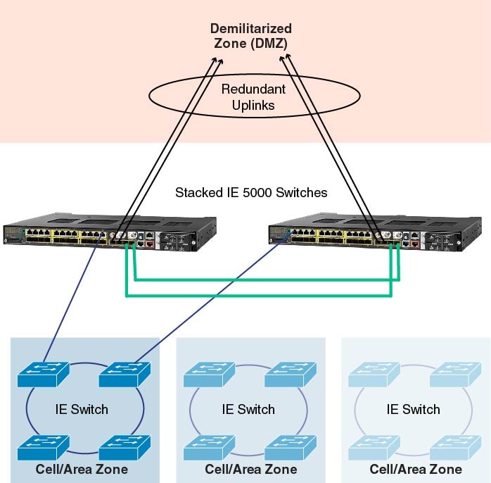
Data path redundancy is built into the stacking architecture because there are two physical paths between any two stack members (represented by the green cables in the figure). Stacking increases Ethernet switch availability by providing redundancy for both the physical switch and the uplink. Because different physical switches connect to the upstream network, losing one switch or one uplink interface does not prevent connectivity to the network. Since the logical switch has multiple uplinks, the logical switch still has network connectivity because at least one uplink is still active.
Stack Operation
In a logical switch, a single physical switch acts as the stack master. The stack master controls the operation of the switch stack, and is the single point of stack-wide management. From the stack master, you configure:
-
System-level (global) features that apply to all stack members
-
Interface-level features for each stack member
The stack master contains the saved and running configuration files for the switch stack. The configuration files include the system-level settings for the switch stack and the interface-level settings for each stack member. Each stack member has a current copy of these files for back-up purposes.
The stack master manages all physical switches, including itself. If the master fails, another member automatically becomes the stack master following an election process. The configuration of the stack is preserved through a single switch failure or a reboot of all stack members. Horizontal stacking provides 1:N redundancy for the stack master, with the ability for any physical switch to back up the acting master.
Deployment Options
Horizontal stacking is disabled by default, with the TenGigabit interfaces of the switch configured in the <slot>/<port number> format. The interfaces behave as normal uplink ports. To enable horizontal stacking, you need to convert any of these available uplink ports to horizontal stacking ports such that the connected ends are configured with same stack port number and reload the switch.
There are two ways to enable horizontal stacking:
-
Connect ports and then enable horizontal stacking.
When you connect the ports and then enable horizontal stacking (by converting uplink ports to horizontal stacking ports), after the switch reloads, the stack is formed. Use this approach to bring up the stack with the desired number of switches (maximum 4) at one time.
- Enable horizontal stacking and then connect ports.
If you expect port density to increase slowly, you can enable one switch (for example, Switch-1) for horizontal stacking (by converting uplink ports to horizontal stacking ports) and reload the switch without connecting the stack ports. After reload, the switch considers itself as the master and operates as a stack with only one member (itself).
To increase port density, you can add another member (for example, Switch-2) to the stack as follows:
-
Enable the horizontal stacking ports on Switch-2 and connect those ports to the horizontal stacking-enabled ports of Switch-1.
-
Provision the configuration for Switch-2 in Switch-1.
-
Reload Switch-2. During the bootup process, Switch-2 detects Switch-1 as the master and becomes a member of the stack with the provisioned configuration. (Switch-1 is the master because the switch with the longest up time becomes the master during the master election process.)
This approach allows you to add more switches to the stack as required without disrupting the network.
-
Feature Support in Stack Mode
This section summarizes horizontal stacking feature support. For information about unsupported features, see Guidelines and Limitations.
Horizontal Stacking Features
Features of horizontal stacking are as follows:
-
Stacking of up to four switches
-
Stack link capacity of 10 Gbps
-
Stack convergence and failover
-
Software-based stack link failure detection
-
Stack CLI for configuration and management
-
SD card support for master and slave switches
Layer 2 Features
The following Layer 2 features are supported in stack mode:
-
Link status detection, speed, duplex
-
Layer 2 learning and forwarding
-
STP, MSTP, RSTP, BPDU Guard
-
VLAN, VTP, DTP, VLAN Table
-
CDP, LLDP
-
UDLD
-
LACP and PAgP
-
Static EtherChannel
-
Flex links
-
IGMP Snooping
-
ARP
-
REP ring convergence
-
Ethernet OAM and CFM
-
MACsec
Layer 3 Features
-
ARP
-
Static Routes
-
Dynamic Routing Protocols: Border Gateway Protocol (BGP), Protocol Independent Multicast (PIM), Virtual Routing and Forwarding (VRF), Open Shortest Path First (OSPF), Policy Based Routing (PBR), and Enhanced Interior Gateway Routing Protocol (EIGRP)
-
Layer 3 host configuration
-
HSRP and VRRP
Power over Ethernet (PoE)
PoE is supported in stack mode.
Traffic Types
The following types of traffic are supported in stack mode:
-
Layer 2 unicast
-
Layer 2 multicast and broadcast
-
Layer 3 unicast
-
Layer 3 multicast and broadcast
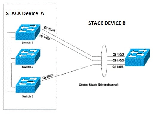
Cross-Stack EtherChannel
You can create an EtherChannel across two physical switches. When devices are stacked, the stack becomes a single logical entity. Nothing special is required to accomplish this once the stack has been configured—just configure each port to be in the same port-channel group. Cisco refers to this configuration as cross-stack EtherChannel. With cross-stack Etherchannel, you can stack up to four devices and configure up to 48 port channels in the stack to provide greater network capacity.
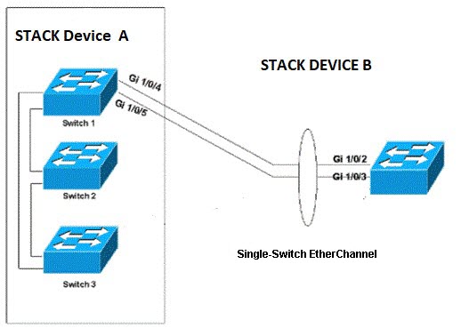
Note that you can use Port Aggregation Protocol (PAgP) only in single-switch EtherChannel configurations; use Link Aggregation Control Protocol (LACP) for cross-stack Etherchannel on the IE 5000. PAgP cannot be enabled on cross-stack EtherChannels. PAgP dynamically groups similarly configured ports on a single switch in the stack into a single logical link.
In the following network diagram, there are two network stacks, Stack A and Stack B. Stack A has three switch members, and Stack B has only one switch member. The EtherChannel is formed with two ports on Switch 1 and one port on Switch 3 of Stack A. These ports connect to the three ports in Stack B. The diagram shows the configuration of one port channel in Link Aggregation Control Protocol (LACP). LACP provides two modes to configure the Etherchannels, Active and Passive.
Ports can form an EtherChannel when they are in different LACP modes as long as the modes are compatible. For example:
-
A port in Active mode can form an EtherChannel with another port that is in Active or Passive mode.
-
A port in Passive mode cannot form an EtherChannel with another port that is also in Passive mode because neither port starts LACP negotiation.
In the following network diagram, there are two network stacks, Stack A and Stack B. Stack A has three switch members, and Stack B has only one switch member. The EtherChannel is formed with two ports on Switch 1. These ports connect to the two ports in Stack B. This diagram shows the configuration of one port channel in PAgP. With PAgP enabled all the ports in the channel should belong to same device of a stack. PAgP provides two modes to configure the EtherChannels, Auto and Desirable.
Ports can form an EtherChannel when they are in different PAgP modes as long as the modes are compatible. For example:
-
A port in Desirable mode can form an EtherChannel with another port that is in Desirable or Auto mode.
-
A port in Auto mode can form an EtherChannel with another port in Desirable mode.
A port in Auto mode cannot form an EtherChannel with another port that is also in Auto mode because neither port starts PAgP negotiation.
Prerequisites
-
From two to four IE-5000-12S12P-10G switches with LANBASE or IP Services licenses are required for Horizontal Stacking.
-
All the switches in the stack must have the same license.
-
All stack members must run the same Cisco IOS software image to ensure compatibility among stack members.
-
All the switches in the stack must use the same SDM template. If a switch uses a different SDM template than the master, configure the switch to use the same SDM template as the master before adding the switch to the stack.
Note
When the stack is coming up, the master can detect an SDM template mismatch of its members. If the master detects a mismatch, it reloads the SDM template with a matching one.
-
Install the supported 10GE SFP+ transceivers and fiber cables for the stacked switches as described in the Cisco IE 5000 Hardened Aggregator Hardware Installation Guide and verify that the 10GE fiber link between the switches is up.
Guidelines and Limitations
-
All interface configurations are lost when changing between non-stack mode and stack mode on a switch, because the interface names change from slot/port in non-stack mode to switch/slot/port in stack mode. For example, GigabitEthernet1/1 changes to GigabitEthernet1/1/1 when the switch is configured for stack mode.
-
When horizontal stacking is enabled and the switch is reloaded, due to the interface name change, configuration on the interface is lost. We recommend that you use the VLAN interface for management access, which is not affected by this change.
-
When you hot swap a horizontal stacking switch, if you reload a stack member with a 1G SFP inserted on a 10G interface, the interface configuration disappears. To avoid this problem, reload the entire stack applicable for IOS 15.2(8)E5 or earlier release.
-
The following features are not supported in stack mode, and the CLI for these features is not visible when the switch is in stack mode:
-
Device Manager (DM)
-
Common Industrial Protocol (CIP)
-
Layer 2 Network Address Translation (L2 NAT)
-
Parallel Redundancy Protocol (PRP)
-
PROFINET and Media Redundancy Protocol (MRP)
When the switch is in stack mode, it does not support MRP in either PROFINET MRP mode or MRP CLI mode.
-
Any other features that are not listed in Feature Support in Stack Mode.
Note
There are many non-IoT features that are not supported in stack mode. These features are not disabled and the CLI for these features is also available. However, if you attempt to use these features in stack mode, they may not function as intended. We recommend that you use only the features listed in Feature Support in Stack Mode. with horizontal stacking.
-
-
Redundancy protocols converge more slowly on a stacked switch due to stacking on fiber interfaces. Refer to individual protocol configuration guides for recommendations. It is recommended to restrict Resilient Ethernet Protocol (REP) to 8 segments with 24 switches per segment.
-
A maximum of two 10G interfaces can be converted to stack ports. After these interfaces are in stack mode, they are not available for normal network operation and do not appear in an interface listing such as show interface status , show ip interface brief , and so on.
-
Converting a network port to or from a stack port requires a switch reload to take effect.
-
If a saved configuration is applied on a stack port that was a network port in the previous reload, the configuration will fail.
-
When no 10G network port is set as stack port, IE 5000 runs in standalone mode. In standalone mode, the switch cannot be stacked with another stack-enabled or standalone IE 5000 switch. IoT protocols can be configured in standalone mode.
-
No features have been modified for stacking.
-
There is no new SDM template and no change in the existing SDM template options.
-
Stack convergence will be slower than 500 ms due to stacking on fiber interfaces.
-
PAgP cannot be enabled on cross-stack EtherChannels.
-
When connecting stacked switches, ensure that hstack port1 on one switch is connected to hstack port1 of the other switch, and hstack port2 is connected to hstack port2 of the other switch.
Default Settings
By default, 10G interfaces are configured to operate as network ports.
Configuring Horizontal Stacking
Follow this procedure to configure up to two of the 10G uplink ports on the IE 5000 as stack ports. Stack ports are designated as stack port 1 or stack port 2. The remaining uplinks on the switch continue to operate as normal uplink ports.
Note |
All interface configurations are lost when changing between non-stack mode and stack mode on a switch because the interface names change from slot/port in non-stack mode to switch/slot/port in stack mode. For example, TenGigabitEthernet1/25 changes to TenGigabitEthernet1/1/25 when the switch is configured for stack mode. |
Note |
|
SUMMARY STEPS
- Enter global configuration mode:
- Convert a 10G network port to a stack port:
- Repeat step 2 for the second TenGigabitEthernet interface to be converted to a stack port.
- Return to privileged EXEC mode:
- (Optional) Save your entries in the configuration file:
- Reload the operating system:
DETAILED STEPS
|
Step 1 |
Enter global configuration mode: configure terminal |
||
|
Step 2 |
Convert a 10G network port to a stack port: switch number hstack-port {1 | 2 } TenGigabitEthernet interface-id
|
||
|
Step 3 |
Repeat step 2 for the second TenGigabitEthernet interface to be converted to a stack port. |
||
|
Step 4 |
Return to privileged EXEC mode: exit |
||
|
Step 5 |
(Optional) Save your entries in the configuration file: copy running-config startup-config |
||
|
Step 6 |
Reload the operating system: reload |
Example
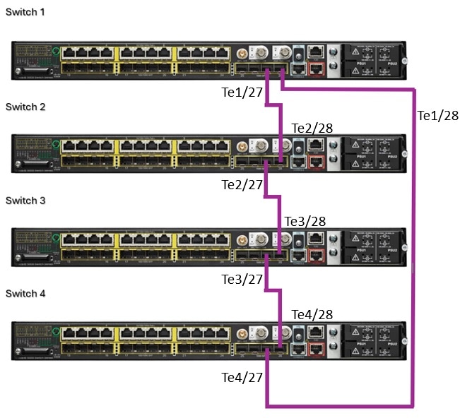
Switch 1
switch# configure terminal
switch(config)# switch 1 hstack-port 1 TenGigabitEthernet 1/27
switch(config)# switch 1 hstack-port 2 TenGigabitEthernet 1/28
switch(config)# exit

Switch 2
switch# configure terminal
switch(config)# switch 2 hstack-port 1 TenGigabitEthernet 1/27
switch(config)# switch 2 hstack-port 2 TenGigabitEthernet 1/28
switch(config)# exit

Switch 3
switch# configure terminal
switch(config)# switch 3 hstack-port 1 TenGigabitEthernet 1/27
switch(config)# switch 3 hstack-port 2 TenGigabitEthernet 1/28
switch(config)# exit

Switch 4
switch# configure terminal
switch(config)# switch 4 hstack-port 1 TenGigabitEthernet 1/27
switch(config)# switch 4 hstack-port 2 TenGigabitEthernet 1/28
switch(config)# exit
Converting a Stack Port to a Network Port
To convert a horizontal stack port back to a TengigabitEthernet uplink port, follow this procedure.
Before you begin
When no 10G network port is configured as a stack port, the IE 5000 will run in standalone mode. The switch in this mode cannot be stacked with another stack-enabled or standalone IE 5000 switch. IoT protocols can be configured in this mode.
SUMMARY STEPS
- Enter global configuration mode:
- Convert a 10G stack port to a network port:
- Return to privileged EXEC mode:
- (Optional) Save your entries in the configuration file:
- Reload the operating system:
DETAILED STEPS
|
Step 1 |
Enter global configuration mode: configure terminal |
||
|
Step 2 |
Convert a 10G stack port to a network port: no switch number hstack-port {1 | 2 }
|
||
|
Step 3 |
Return to privileged EXEC mode: exit |
||
|
Step 4 |
(Optional) Save your entries in the configuration file: copy running-config startup-config |
||
|
Step 5 |
Reload the operating system: reload |
Example
Switch(config)#no switch 1 hstack-port 1
switch(config)# exit
switch# copy running-config startup-config
switch# reload
Verifying Configuration
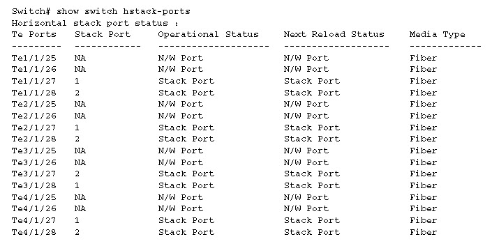
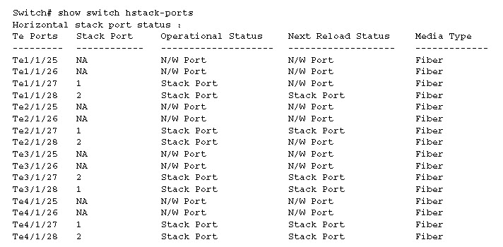
To display the stacking status of the 10G ports, enter the following show command:
Switch#show switch hstack-ports
The command output shows:
-
All the 10G ports available on the master and all members that are capable of horizontal stacking.
-
The stack port number—1 or 2, corresponding to any 10G port that has been converted to a horizontal stack port.
-
Operational status of the 10G port—Stack Port or N/W (network (uplink) port).
-
The status of the 10G port at the next reload.
-
The media type.
Any 10G port that is configured as a horizontal stack port can be converted back to a normal uplink port. This will be effective only after the next reload.
The following example shows output for a four-member full ring horizontal stack on the IE 5000:
The following example shows the output when Te1/1/27 and Te2/1/28 are converted back to N/W ports, but the switches have not been reloaded:
To display the role of a stack port, use the show switch command:
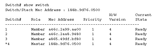
The preceding example shows that member 4 is the master. All stack members have a stack priority of 1 (the default).
Possible stack member states are:
-
Ready—Member is up and part of the stack.
-
Progressing—Member is booting up.
-
Mismatch—A hardware or software mismatch is preventing the member from fully joining.
-
Provisioned—Member has been configured, but is not part of the stack and has never been part of the stack.
-
Removed—Member is not currently powered on or was removed from the stack.
The MAC address of the master is used as the MAC address of the logical stack. This is the base MAC address from the master, and is used for all IP communications, as well as Cisco Discovery Protocol data exchange and Spanning Tree Protocol.
To view other operational aspects of the stack, these commands are useful:
-
show version —View the Cisco IOS Software version of all stack members. Useful if there is a mismatch.
-
show switch neighbors —View which members are connected to which stack ports.
-
show switch stack-ring speed —View details of the stack ring, for example:
Switch#show
 switch stack-ring speed
Stack Ring Speed : 10G
Stack Ring Configuration: Full
Stack Ring Protocol : FlexStack
Switch#
Configuration Example
This example shows how to convert two 10G uplink ports from network ports to stack ports:
Switch#config t
Enter configuration commands, one per line.  End with CNTL/Z.
Switch(config)#switch 1 hstack-port 1 TenGigabitEthernet 1/25
Do you want to continue?[confirm]
New port setting will be effective after next reload
Switch(config)#switch 1 hstack-port 2 TenGigabitEthernet 1/26
Do you want to continue?[confirm]
New port setting will be effective after next reload
Te1/25 will be assigned as horizontal stack port 1
Te1/26 will be assigned as horizontal stack port 2
This example shows how to convert a stack port to a network port:
Switch(config)#no switch 1 hstack-port 1

Do you want to continue?[confirm]
New port setting will be effective after next reload
Related Documents
For Cisco Industrial Ethernet 5000 Series Switches documentation, see http://www.cisco.com/go/ie5000 .
Feature History
|
Platform |
Feature |
First Supported Release |
|---|---|---|
|
IE-5000-12S12P-10G |
Precision Time Protocol (PTP) added to features supported in stack mode. |
Cisco IOS Release 15.2(8)E |
|
Maximum supported Portchannel number increased to 48. CFM/OAM, HSRP, VRRP, and MACsec added to features supported in stack mode. |
Cisco IOS Release 15.2(7)E1a |
|
|
Layer 3 Dynamic Routing Support for BGP, PIM, VRF, OSPF, PBR, and EIGRP. |
Cisco IOS Release 15.2(7)E |
|
|
Horizontal Stacking. |
Cisco IOS Release 15.2(5)E |
 Feedback