- Preface
- Overview
- Using the Command-Line Interface
- Configuring the Switch Alarms
- Performing Switch Setup Configuration
- Configuring Cisco IOS Configuration Engine
- Configuring Switch Clusters
- Performing Switch Administration
- Configuring PTP
- Configuring PROFINET
- Configuring CIP
- Configuring SDM Templates
- Configuring Switch-Based Authentication
- Configuring IEEE 802.1x Port-Based Authentication
- Configuring Web-Based Authentication
- Configuring SGT Exchange Protocol over TCP (SXP) and Layer 3 Transport
- Configuring Interface Characteristics
- Configuring Smartports Macros
- Configuring VLANs
- Configuring VTP
- Configuring Voice VLAN
- Configuring STP
- Configuring MSTP
- Configuring Optional Spanning-Tree Features
- Configuring Resilient Ethernet Protocol
- Configuring Flex Links and the MAC Address-Table Move Update Feature
- Configuring DHCP
- Configuring Dynamic ARP Inspection
- Configuring IP Source Guard
- Configuring IGMP Snooping and MVR
- Configuring Port-Based Traffic Control
- Configuring SPAN and RSPAN
- Configuring LLDP, LLDP-MED, and Wired Location Service
- Configuring CDP
- Configuring UDLD
- Configuring RMON
- Configuring System Message Logging
- Configuring SNMP
- Configuring Network Security with ACLs
- Configuring Standard QoS
- Configuring Auto-QoS
- Configuring EtherChannels
- Configuring Static IP Unicast Routing
- Configuring IPv6 Host Functions
- Configuring Link State Tracking
- Configuring IPv6 MLD Snooping
- Configuring Cisco IOS IP SLAs Operations
- Troubleshooting the Cisco IOS Software
- Working with the Cisco IOS File System, Configuration Files, and Software Images
Software Configuration Guide, Cisco IOS Release 15.2(2)E (Industrial Ethernet 2000 Switch)
Bias-Free Language
The documentation set for this product strives to use bias-free language. For the purposes of this documentation set, bias-free is defined as language that does not imply discrimination based on age, disability, gender, racial identity, ethnic identity, sexual orientation, socioeconomic status, and intersectionality. Exceptions may be present in the documentation due to language that is hardcoded in the user interfaces of the product software, language used based on RFP documentation, or language that is used by a referenced third-party product. Learn more about how Cisco is using Inclusive Language.
- Updated:
- July 16, 2014
Chapter: Configuring Interface Characteristics
- Finding Feature Information
- Restrictions for Configuring Interface Characteristics
- Information About Configuring Interface Characteristics
- How to Configure Interface Characteristics
- Configuring Ethernet Interfaces
- Monitoring and Maintaining Interface Characteristics
- Configuration Examples for Configuring Interface Characteristics
- Additional References
Configuring Interface Characteristics
Finding Feature Information
Your software release may not support all the features documented in this chapter. For the latest feature information and caveats, see the release notes for your platform and software release.
Use Cisco Feature Navigator to find information about platform support and Cisco software image support. To access Cisco Feature Navigator, go to http://www.cisco.com/go/cfn. An account on Cisco.com is not required.
Restrictions for Configuring Interface Characteristics
Information About Configuring Interface Characteristics
Interface Types
This section describes the different types of interfaces supported by the switch with references to chapters that contain more detailed information about configuring these interface types.
Port-Based VLANs
A VLAN is a switched network that is logically segmented by function, team, or application, without regard to the physical location of the users. For more information about VLANs, see the Chapter18, “Configuring VLANs” Packets received on a port are forwarded only to ports that belong to the same VLAN as the receiving port. Network devices in different VLANs cannot communicate with one another without a Layer 3 device to route traffic between the VLANs.
VLAN partitions provide hard firewalls for traffic in the VLAN, and each VLAN has its own MAC address table. A VLAN comes into existence when a local port is configured to be associated with the VLAN, when the VLAN Trunking Protocol (VTP) learns of its existence from a neighbor on a trunk, or when a user creates a VLAN.
To configure VLANs, use the vlan vlan-id global configuration command to enter VLAN configuration mode. The VLAN configurations for normal-range VLANs (VLAN IDs 1 to 1005) are saved in the VLAN database. If VTP is version 1 or 2, to configure extended-range VLANs (VLAN IDs 1006 to 4096), you must first set VTP mode to transparent. Extended-range VLANs created in transparent mode are not added to the VLAN database but are saved in the switch running configuration. With VTP version 3, you can create extended-range VLANs in client or server mode. These VLANs are saved in the VLAN database.
Add ports to a VLAN by using the switchport interface configuration commands:
Switch Ports
Switch ports are Layer 2-only interfaces associated with a physical port. You can configure a port as an access port or trunk port or let the Dynamic Trunking Protocol (DTP) operate on a per-port basis to set the switchport mode by negotiating with the port on the other end of the link. Switch ports are used for managing the physical interface and associated Layer 2 protocols.
Configure switch ports by using the switchport interface configuration commands. Use the switchport command with no keywords to put an interface that is in Layer 3 mode into Layer 2 mode.

Note![]() When you put an interface that is in Layer 3 mode into Layer 2 mode, the previous configuration information related to the affected interface might be lost, and the interface is returned to its default configuration.
When you put an interface that is in Layer 3 mode into Layer 2 mode, the previous configuration information related to the affected interface might be lost, and the interface is returned to its default configuration.
For detailed information about configuring access port and trunk port characteristics, see Chapter18, “Configuring VLANs”
Note![]() The LAN base image supports static routing.
The LAN base image supports static routing.
Access Ports
An access port belongs to and carries the traffic of only one VLAN (unless it is configured as a voice VLAN port). Traffic is received and sent in native formats with no VLAN tagging. Traffic arriving on an access port is assumed to belong to the VLAN assigned to the port.
Two types of access ports are supported:
- Static access ports are manually assigned to a VLAN.
- VLAN membership of dynamic access ports is learned through incoming packets. By default, a dynamic access port is not a member of any VLAN, and forwarding to and from the port is enabled only when the VLAN membership of the port is discovered. Dynamic access ports on the switch are assigned to a VLAN by a VLAN Membership Policy Server (VMPS). The VMPS can be a Catalyst 6500 series switch; the switch cannot be a VMPS server.
You can also configure an access port with an attached Cisco IP Phone to use one VLAN for voice traffic and another VLAN for data traffic from a device attached to the phone. For more information about voice VLAN ports, see Chapter20, “Configuring Voice VLAN”
Trunk Ports
A trunk port carries the traffic of multiple VLANs and by default is a member of all VLANs in the VLAN database.
The switch supports only IEEE 802.1Q trunk ports. An IEEE 802.1Q trunk port supports simultaneous tagged and untagged traffic. An IEEE 802.1Q trunk port is assigned a default port VLAN ID (PVID), and all untagged traffic travels on the port default PVID. All untagged traffic and tagged traffic with a NULL VLAN ID are assumed to belong to the port default PVID. A packet with a VLAN ID equal to the outgoing port default PVID is sent untagged. All other traffic is sent with a VLAN tag.
Although by default, a trunk port is a member of every VLAN known to the VTP, you can limit VLAN membership by configuring an allowed list of VLANs for each trunk port. The list of allowed VLANs does not affect any other port but the associated trunk port. By default, all possible VLANs (VLAN ID 1 to 4096) are in the allowed list. A trunk port can become a member of a VLAN only if VTP knows of the VLAN and if the VLAN is in the enabled state. If VTP learns of a new, enabled VLAN and the VLAN is in the allowed list for a trunk port, the trunk port automatically becomes a member of that VLAN and traffic is forwarded to and from the trunk port for that VLAN. If VTP learns of a new, enabled VLAN that is not in the allowed list for a trunk port, the port does not become a member of the VLAN, and no traffic for the VLAN is forwarded to or from the port.
For more information about trunk ports, see Chapter18, “Configuring VLANs”
EtherChannel Port Groups
Note![]() The LAN Base image supports EtherChannel port groups.
The LAN Base image supports EtherChannel port groups.
EtherChannel port groups treat multiple switch ports as one switch port. These port groups act as a single logical port for high-bandwidth connections between switches or between switches and servers. An EtherChannel balances the traffic load across the links in the channel. If a link within the EtherChannel fails, traffic previously carried over the failed link changes to the remaining links. You can group multiple trunk ports into one logical trunk port or group multiple access ports into one logical access port.
Most protocols operate over either single ports or aggregated switch ports and do not recognize the physical ports within the port group. Exceptions are the DTP, the Cisco Discovery Protocol (CDP), and the Port Aggregation Protocol (PAgP), which operate only on physical ports.
When you configure an EtherChannel, you create a port-channel logical interface and assign an interface to the EtherChannel. Use the channel-group interface configuration command to dynamically create the port-channel logical interface. This command binds the physical and logical ports together.
For Layer 3 interfaces, you manually create the logical interface by using the interface port-channel global configuration command. Then you manually assign an interface to the EtherChannel by using the channel-group interface configuration command.
For more information, see Chapter41, “Configuring EtherChannels”
Dual-Purpose Uplink Ports
Some switches support dual-purpose uplink ports. Each uplink port is considered as a single interface with dual front ends—an RJ-45 connector and a small form-factor pluggable (SFP) module connector. The dual front ends are not redundant interfaces, and the switch activates only one connector of the pair.
By default, the switch dynamically selects the interface type that first links up. However, you can use the media-type interface configuration command to manually select the RJ-45 connector or the SFP module connector. To return to the default setting, use the media-type auto interface or the no media-type interface configuration commands.
Each uplink port has two LEDs: one shows the status of the RJ-45 port, and one shows the status of the SFP module port. The port LED is on for whichever connector is active. For more information about the LEDs, see the Hardware Installation Guide.
The switch configures both types to autonegotiate speed and duplex (the default). If you configure auto-select, you cannot configure the speed and duplex interface configuration commands.
When the switch powers on or when you enable a dual-purpose uplink port through the shutdown and the no shutdown interface configuration commands, the switch gives preference to the SFP module interface. In all other situations, the switch selects the active link based on which type first links up.
Connecting Interfaces
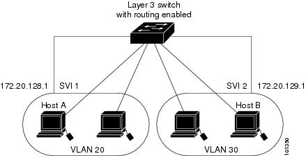
Devices within a single VLAN can communicate directly through any switch. Ports in different VLANs cannot exchange data without going through a routing device.
With a standard Layer 2 switch, ports in different VLANs have to exchange information through a router. By using the switch with routing enabled, when you configure both VLAN 20 and VLAN 30 with an SVI to which an IP address is assigned, packets can be sent from Host A to Host B directly through the switch with no need for an external router (Figure 16-1).
Figure 16-1 Connecting VLANs with a Layer 3 Switch
Basic routing (static routing and RIP) is supported on the LAN base image. Whenever possible, to maintain high performance, forwarding is done by the switch hardware. However, only IP Version 4 packets with Ethernet II encapsulation can be routed in hardware. Non-IP traffic and traffic with other encapsulation methods can be fallback-bridged by hardware.
The routing function can be enabled on all SVIs and routed ports. The switch routes only IP traffic. When IP routing protocol parameters and address configuration are added to an SVI or routed port, any IP traffic received from these ports is routed.For more information, see Chapter42, “Configuring Static IP Unicast Routing”
- Fallback bridging forwards traffic that the switch does not route or traffic belonging to a nonroutable protocol, such as DECnet. Fallback bridging connects multiple VLANs into one bridge domain by bridging between two or more SVIs or routed ports. When configuring fallback bridging, you assign SVIs or routed ports to bridge groups with each SVI or routed port assigned to only one bridge group. All interfaces in the same group belong to the same bridge domain.
Using Interface Configuration Mode
The switch supports these interface types:
- Physical ports—switch ports and routed ports
- VLANs—switch virtual interfaces
- Port channels—EtherChannel interfaces
You can also configure a range of interfaces (see the “Configuring a Range of Interfaces” section).
To configure a physical interface (port), specify the interface type, and switch port number, and enter interface configuration mode.
- Type —Port types depend on those supported on the switch. Possible types are Fast Ethernet (fastethernet or fa) for 10/100 Mb/s Ethernet, Gigabit Ethernet (gigabitethernet or gi) for 10/100/1000 Mb/s Ethernet ports, or small form-factor pluggable (SFP) module Gigabit Ethernet interfaces.
- Port number—The physical interface number on the switch. The port numbers for the IE-2000-4TC switch model are 1–4 for the Fast Ethernet ports and 1–2 for the Gigabit Ethernet ports. The port numbers for the IE-2000-8TC switch model are 1–8 for the Fast Ethernet ports and 1–2 for the Gigabit Ethernet ports. Table 16-1 shows the switch and module combinations and the interface numbers.
You can identify physical interfaces by looking at the switch. You can also use the show privileged EXEC commands to display information about a specific interface or all the interfaces.
Default Ethernet Interface Settings
For more details on the VLAN parameters listed in the table, see Chapter18, “Configuring VLANs” For details on controlling traffic to the port, see Chapter30, “Configuring Port-Based Traffic Control”
Note![]() To configure Layer 2 parameters, if the interface is in Layer 3 mode, you must enter the switchport interface configuration command without any parameters to put the interface into Layer 2 mode. This shuts down the interface and then reenables it, which might generate messages on the device to which the interface is connected. When you put an interface that is in Layer 3 mode into Layer 2 mode, the previous configuration information related to the affected interface might be lost, and the interface is returned to its default configuration.
To configure Layer 2 parameters, if the interface is in Layer 3 mode, you must enter the switchport interface configuration command without any parameters to put the interface into Layer 2 mode. This shuts down the interface and then reenables it, which might generate messages on the device to which the interface is connected. When you put an interface that is in Layer 3 mode into Layer 2 mode, the previous configuration information related to the affected interface might be lost, and the interface is returned to its default configuration.
|
|
|
|---|---|
Switch port mode dynamic auto (supports DTP) (Layer 2 interfaces only). |
|
Flow control is set to receive : off. It is always off for sent packets. |
|
Disabled on all Ethernet ports. Chapter41, “Configuring EtherChannels” |
|
Port blocking (unknown multicast and unknown unicast traffic) |
|
| Note The switch might not support a prestandard powered device—such as Cisco IP phones and access points that do not fully support IEEE 802.3af—if that powered device is connected to the switch through a crossover cable. This is regardless of whether auto-MIDX is enabled on the switch port. |
|
Interface Speed and Duplex Mode
Depending on the supported port types, Ethernet interfaces on the switch operate at 10, 100, or 1000 Mb/s, or in either full- or half-duplex mode. In full-duplex mode, two stations can send and receive traffic at the same time. Normally, 10-Mb/s ports operate in half-duplex mode, which means that stations can either receive or send traffic.
Switch models can include combinations of Fast Ethernet (10/100-Mb/s) ports, Gigabit Ethernet (10/100/1000-Mb/s) ports, and small form-factor pluggable (SFP) module slots supporting SFP modules.
Speed and Duplex Configuration Guidelines
When configuring an interface speed and duplex mode, note these guidelines:
- Fast Ethernet (10/100-Mb/s) ports support all speed and duplex options.
- Gigabit Ethernet (10/100/1000-Mb/s) ports support all speed options and all duplex options (auto, half, and full). However, Gigabit Ethernet ports operating at 1000 Mb/s do not support half-duplex mode.
- For SFP module ports, the speed and duplex CLI options change depending on the SFP module type:
–![]() The 1000BASE- x (where - x is -BX, -CWDM, -LX, -SX, and -ZX) SFP module ports support the nonegotiate keyword in the speed interface configuration command. Duplex options are not supported.
The 1000BASE- x (where - x is -BX, -CWDM, -LX, -SX, and -ZX) SFP module ports support the nonegotiate keyword in the speed interface configuration command. Duplex options are not supported.
–![]() The 1000BASE-T SFP module ports support the same speed and duplex options as the 10/100/1000-Mb/s ports.
The 1000BASE-T SFP module ports support the same speed and duplex options as the 10/100/1000-Mb/s ports.
–![]() The 100BASE- x (where - x is -BX, -CWDM, -LX, -SX, and -ZX) SFP module ports support only 100 Mb/s. These modules support full- and half- duplex options but do not support autonegotiation.
The 100BASE- x (where - x is -BX, -CWDM, -LX, -SX, and -ZX) SFP module ports support only 100 Mb/s. These modules support full- and half- duplex options but do not support autonegotiation.
For information about which SFP modules are supported on your switch, see the product release notes.
- If both ends of the line support autonegotiation, we highly recommend the default setting of auto negotiation.
- If you configure the speed as nonegotiate on one device and configure auto negotiation on the remote device, the port may go down on some platforms. The IEEE specification does not define the expected behavior of an auto negotiation mismatch on a 1000BaseX link. The link may or may not come up.
- If one interface supports autonegotiation and the other end does not, configure duplex and speed on both interfaces; do not use the auto setting on the supported side.
- When STP is enabled and a port is reconfigured, the switch can take up to 30 seconds to check for loops. The port LED is amber while STP reconfigures.

IEEE 802.3x Flow Control
Flow control enables connected Ethernet ports to control traffic rates during congestion by allowing congested nodes to pause link operation at the other end. If one port experiences congestion and cannot receive any more traffic, it notifies the other port by sending a pause frame to stop sending until the condition clears. Upon receipt of a pause frame, the sending device stops sending any data packets, which prevents any loss of data packets during the congestion period.
Note![]() Ports on the switch can receive, but not send, pause frames.
Ports on the switch can receive, but not send, pause frames.
You use the flowcontrol interface configuration command to set the interface’s ability to receive pause frames to on, off, or desired. The default state is off.
When set to desired, an interface can operate with an attached device that is required to send flow-control packets or with an attached device that is not required to but can send flow-control packets.
These rules apply to flow control settings on the device:
- receive on (or desired)—The port cannot send pause frames but can operate with an attached device that is required to or can send pause frames; the port can receive pause frames.
- receive off —Flow control does not operate in either direction. In case of congestion, no indication is given to the link partner, and no pause frames are sent or received by either device.
Auto-MDIX on an Interface
When automatic medium-dependent interface crossover (auto-MDIX) is enabled on an interface, the interface automatically detects the required cable connection type (straight through or crossover) and configures the connection appropriately. When connecting switches without the auto-MDIX feature, you must use straight-through cables to connect to devices such as servers, workstations, or routers and crossover cables to connect to other switches or repeaters. With auto-MDIX enabled, you can use either type of cable to connect to other devices, and the interface automatically corrects for any incorrect cabling. For more information about cabling requirements, see the Hardware Installation Guide.
Auto-MDIX is enabled by default. When you enable auto-MDIX, you must also set the interface speed and duplex to auto so that the feature operates correctly.
Auto-MDIX is supported on all 10/100 and 10/100/1000-Mb/s interfaces. It is not supported on 1000BASE-SX or -LX SFP module interfaces.
SVI Autostate Exclude
Configuring SVI autostate exclude on an access or trunk port in an SVI excludes that port in the calculation of the status of the SVI (up or down line state) even if it belongs to the same VLAN. When the excluded port is in the up state, and all other ports in the VLAN are in the down state, the SVI state is changed to down.
At least one port in the VLAN should be up and not excluded to keep the SVI line state up. You can use this command to exclude the monitoring port status when determining the status of the SVI.
System MTU
The default maximum transmission unit (MTU) size for frames received and transmitted on all interfaces is 1500 bytes. You can increase the MTU size for all interfaces operating at 10 or 100 Mb/s by using the system mtu global configuration command. You can increase the MTU size to support jumbo frames on all Gigabit Ethernet interfaces by using the system mtu jumbo global configuration command.
You can change the MTU size for routed ports by using the system mtu routing global configuration command.
Note![]() You cannot configure a routing MTU size that exceeds the system MTU size. If you change the system MTU size to a value smaller than the currently configured routing MTU size, the configuration change is accepted, but not applied until the next switch reset. When the configuration change takes effect, the routing MTU size automatically defaults to the new system MTU size.
You cannot configure a routing MTU size that exceeds the system MTU size. If you change the system MTU size to a value smaller than the currently configured routing MTU size, the configuration change is accepted, but not applied until the next switch reset. When the configuration change takes effect, the routing MTU size automatically defaults to the new system MTU size.
Gigabit Ethernet ports are not affected by the system mtu command; 10/100 ports are not affected by the system mtu jumbo command. If you d o not configure the system mtu jumbo command, the setting of the system mtu command applies to all Gigabit Ethernet interfaces.
You cannot set the MTU size for an individual interface; you set it for all 10/100 or all Gigabit Ethernet interfaces. When you change the system or jumbo MTU size, you must reset the switch before the new configuration takes effect.The system mtu routing command does not require a switch reset to take effect.
Frames sizes that can be received by the switch CPU are limited to 1998 bytes, no matter what value was entered with the system mtu or system mtu jumbo commands. Although frames that are forwarded or routed are typically not received by the CPU, in some cases packets are sent to the CPU, such as traffic sent to control traffic, SNMP, Telnet, or routing protocols.
Routed packets are subjected to MTU checks on the output ports. The MTU value used for routed ports is derived from the applied system mtu value (not the system mtu jumbo value). That is, the routed MTU is never greater than the system MTU for any VLAN. The routing protocols use the system MTU value when negotiating adjacencies and the MTU of the link. For example, the Open Shortest Path First (OSPF) protocol uses this MTU value before setting up an adjacency with a peer router. To view the MTU value for routed packets for a specific VLAN, use the show platform port-asic mvid privileged EXEC command.
Note![]() If Layer 2 Gigabit Ethernet interfaces are configured to accept frames greater than the 10/100 interfaces, jumbo frames received on a Layer 2 Gigabit Ethernet interface and sent on a Layer 2 10/100 interface are dropped.
If Layer 2 Gigabit Ethernet interfaces are configured to accept frames greater than the 10/100 interfaces, jumbo frames received on a Layer 2 Gigabit Ethernet interface and sent on a Layer 2 10/100 interface are dropped.
How to Configure Interface Characteristics
Configuring Layer 3 Interfaces
Configuring Interfaces
These general instructions apply to all interface configuration processes.
Step 1![]() Enter the configure terminal command at the privileged EXEC prompt:
Enter the configure terminal command at the privileged EXEC prompt:
Step 2![]() Enter the interface global configuration command.
Enter the interface global configuration command.
Identify the interface type and the interface number, Gigabit Ethernet port 1 in this example:
Note![]() Entering a space between the interface type and interface number is optional
Entering a space between the interface type and interface number is optional
Step 3![]() Follow each interface command with the configuration commands that the interface requires. The commands that you enter define the protocols and applications that will run on the interface. The commands are collected and applied to the interface when you enter another interface command or enter end to return to privileged EXEC mode.
Follow each interface command with the configuration commands that the interface requires. The commands that you enter define the protocols and applications that will run on the interface. The commands are collected and applied to the interface when you enter another interface command or enter end to return to privileged EXEC mode.
You can also configure a range of interfaces by using the interface range or interface range macro global configuration commands. Interfaces configured in a range must be the same type and must be configured with the same feature options.
Step 4![]() After you configure an interface, verify its status by using the show privileged EXEC commands listed in the “Monitoring and Maintaining Interface Characteristics” section.
After you configure an interface, verify its status by using the show privileged EXEC commands listed in the “Monitoring and Maintaining Interface Characteristics” section.
Enter the show interfaces privileged EXEC command to see a list of all interfaces on or configured for the switch. A report is provided for each interface that the device supports or for the specified interface.
Configuring a Range of Interfaces
You can use the interface range global configuration command to configure multiple interfaces with the same configuration parameters. When you enter the interface-range configuration mode, all command parameters that you enter are attributed to all interfaces within that range until you exit this mode.
Interface Range Restrictions
- When you use the interface range command with port channels, the first and last port-channel number must be active port channels.
- The interface range command only works with VLAN interfaces that have been configured with the interface vlan command. The show running-config privileged EXEC command displays the configured VLAN interfaces. VLAN interfaces not displayed by the show running-config command cannot be used with the interface range command.
- All interfaces defined as in a range must be the same type (all Fast Ethernet ports, all Gigabit Ethernet ports, all EtherChannel ports, or all VLANs), but you can combine multiple interface types in a macro.
Configuring and Using Interface Range Macros
You can create an interface range macro to automatically select a range of interfaces for configuration. Before you can use the macro keyword in the interface range macro global configuration command string, you must use the define interface-range global configuration command to define the macro.
Configuring Ethernet Interfaces
Setting the Type of a Dual-Purpose Uplink Port
Perform this task to select which dual-purpose uplink to activate so that you can set the speed and duplex. This procedure is optional.
Setting the Interface Speed and Duplex Parameters
Configuring IEEE 802.3x Flow Control
|
|
|
|
|---|---|---|
Specifies the physical interface to be configured, and enter interface configuration mode. |
||
Configuring Auto-MDIX on an Interface
Adding a Description for an Interface
|
|
|
|
|---|---|---|
Specifies the interface for which you are adding a description, and enters interface configuration mode. |
||
Configuring SVI Autostate Exclude
Configuring the System MTU
Monitoring and Maintaining Interface Characteristics
Monitoring Interface Status
Clearing and Resetting Interfaces and Counters
|
|
|
|---|---|
| Note This command does not clear counters retrieved by using Simple Network Management Protocol (SNMP), but only those seen with the show interface privileged EXEC command. |
|
Shutting Down and Restarting the Interface
Shutting down an interface disables all functions on the specified interface and marks the interface as unavailable on all monitoring command displays. This information is communicated to other network servers through all dynamic routing protocols. The interface is not mentioned in any routing updates.
Configuration Examples for Configuring Interface Characteristics
Configuring the Interface Range: Examples
This example shows how to use the interface range global configuration command to set the speed on ports 1 to 2 to 100 Mb/s:
This example shows how to use a comma to add different interface type strings to the range to enable Fast Ethernet ports 1 to 3 and Gigabit Ethernet ports 1 and 2 to receive flow-control pause frames:
If you enter multiple configuration commands while you are in interface-range mode, each command is executed as it is entered. The commands are not batched and executed after you exit interface-range mode. If you exit interface-range configuration mode while the commands are being executed, some commands might not be executed on all interfaces in the range. Wait until the command prompt reappears before exiting interface-range configuration mode.
Configuring Interface Range Macros: Examples
This example shows how to define an interface-range named enet_list to include ports 1 and 2 and to verify the macro configuration:
This example shows how to create a multiple-interface macro named macro1 :
This example shows how to enter interface-range configuration mode for the interface-range macro enet_list :
This example shows how to delete the interface-range macro enet_list and to verify that it was deleted.
Setting Speed and Duplex Parameters: Example
This example shows how to set the interface speed to 10 Mb/s and the duplex mode to half on a 10/100 Mb/s port:
This example shows how to set the interface speed to 100 Mb/s on a 10/100/1000 Mb/s port:
Enabling auto-MDIX: Example
This example shows how to enable auto-MDIX on a port:
Adding a Description on a Port: Example
This example shows how to add a description on a port and how to verify the description:
Configuring SVI Autostate Exclude: Example
This example shows how to configure an access or trunk port in an SVI to be excluded from the status calculation:
Additional References
The following sections provide references related to switch administration:
Related Documents
|
|
|
|---|---|
Standards
|
|
|
|---|---|
No new or modified standards are supported by this feature, and support for existing standards has not been modified by this feature. |
MIBs
|
|
|
|---|---|
To locate and download MIBs, use the Cisco MIB Locator found at the following URL: https://cfnng.cisco.com/mibs |
RFCs
|
|
|
|---|---|
No new or modified RFCs are supported by this feature, and support for existing RFCs has not been modified by this feature. |
 Feedback