Cisco Catalyst 3850 Series and Cisco Catalyst 3650 Series Switches Best Practices Guide
Bias-Free Language
The documentation set for this product strives to use bias-free language. For the purposes of this documentation set, bias-free is defined as language that does not imply discrimination based on age, disability, gender, racial identity, ethnic identity, sexual orientation, socioeconomic status, and intersectionality. Exceptions may be present in the documentation due to language that is hardcoded in the user interfaces of the product software, language used based on RFP documentation, or language that is used by a referenced third-party product. Learn more about how Cisco is using Inclusive Language.
- Updated:
- December 1, 2015
Chapter: Access Control on the Wired Network
- Prerequisites for Access Control on the Wired Network
- Restrictions for Access Control on the Wired Network
- Identify Configuration Values
- LAN Access Switch Topology with IEEE 802.1x Secure Access Control
- Securing Access Using 802.1x on a wired LAN
- Show Running Configuration for Provisioning Modes
- Monitoring IEEE 802. 1x Status and Statistics
Access Control on the Wired Network
This workflow describes a phased approach to deploy IEEE 802.1x port-based authentication to provide secure and identity-based access control at the edge of the switch stack network.
Prerequisites for Access Control on the Wired Network
- Before globally enabling IEEE 802.1x authentication, remove the EtherChannel configuration from all of the interfaces.
- Define the authenticator (switch) to RADIUS server communication.
- Initiate Extensible Authentication Protocol (EAP) over LAN (EAPoL) messaging to successfully authenticate the end device (or supplicant).
- Based on your requirements, choose an appropriate EAP method. For information, see the Wired 802.1x Deployment Guide.
- Automate the certificate enrollment process for supplicants, as described in the Certificate Autoenrollment in Windows Server 2003.
- Enable machine authentication for end points, such as printers, to ensure that user login is supported.
Restrictions for Access Control on the Wired Network
- You cannot configure an IEEE 802.1x port that is a member of an EtherChannel.
- Destination ports configured with Switched Port Analyzer (SPAN) and remote SPAN (RSPAN) cannot be enabled with IEEE 802.1x authentication.
- You cannot enable an IEEE 802.1x port on trunk or dynamic ports. Dynamic ports can negotiate with its neighbors to become a trunk.
- Do not use port security with IEEE 802.1x. When IEEE 802.1x is enabled, port security then becomes redundant and might interfere with the IEEE 802.1x functionality.
Identify Configuration Values
We recommend that you identify certain switch configuration values in advance so that you can proceed without interruption. We recommend that you take a print out of Table 7, and, as you follow the configuration sequence, replace the values in column B with your values in column C.

Note![]() Depending on your authentication server settings, the authentication and accounting ports could be assigned the values 1812 and 1813 respectively.
Depending on your authentication server settings, the authentication and accounting ports could be assigned the values 1812 and 1813 respectively.
Note![]() Replace the blue italicized example values with your own values.
Replace the blue italicized example values with your own values.
|
|
|
|
|---|---|---|
Note![]() Configuration examples begin in global configuration mode, unless noted otherwise.
Configuration examples begin in global configuration mode, unless noted otherwise.
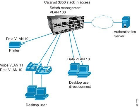
LAN Access Switch Topology with IEEE 802.1x Secure Access Control
Figure 9 LAN Access Switch Topology with IEEE 802.1x Secure Access Control
Securing Access Using 802.1x on a wired LAN
The following tasks are to be performed in the same order that is listed here.
- Recommendations for Configuring Security on a Wired LAN
- Provision Common Wired Security Access
- Provision in Monitor Mode
- Provision in Low-Impact Mode
- Provision in High-Impact Mode
Recommendations for Configuring Security on a Wired LAN
IEEE 802.1x permits or denies network connectivity based on the identity of users and devices. It provides a link between the user name and IP address, MAC address, and a port on a switch. It also provides customized network access based on the identity of the end device or user.
The main components of IEEE 802.1x are:
To provide secure access to your wired switch network, we recommend that you first provision your common wired security features. Provision security modes in phased deployments (monitor mode to high-security mode) of IEEE 802.1x authentication along with MAC Authentication Bypass (MAB), which uses the MAC address of the end device (or supplicant) to make decisions about access.
Note![]() Each phased deployment should occur over time after ensuring that your network is ready to transition to the next security mode.
Each phased deployment should occur over time after ensuring that your network is ready to transition to the next security mode.
Table 8 describes the recommended IEEE 802.1x deployment scenarios that will have limited impact on network access. Test your network infrastructure while in monitor mode. If you are satisfied, then transition to low-impact mode and allow a subset of network traffic to pass through. Finally, transition to high-security mode, requiring authorization from all end devices.
|
|
|
|
|---|---|---|
For detailed information about wired mode deployments, see the TrustSec Phased Deployment Configuration Guide.
For basic information about IEEE 802.1x protocols, see the “8021X Protocols” section of the Wired 802.1X Deployment Guide.
Provision Common Wired Security Access
IEEE 802.1x port host modes determine whether more than one client can be authenticated on the port and how authentications is enforced:
Unless otherwise noted, we recommend that multiple-authentication mode be configured instead of single-host mode, for increased security:
- Multi-authentication mode authenticates all the devices that gain access to the network through a single switch port, such as devices connected through IP phones.
- Multi-authentication mode is more secure than multi-host mode (which also allows multiple data devices) because it authenticates all the devices that try to gain access to the network.
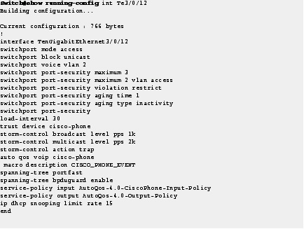
Step 1![]() Run the show run command on your switch to ensure that your access interface connections are set up.
Run the show run command on your switch to ensure that your access interface connections are set up.
This output is what you inherit after performing the “Access Interface Connectivity” workflow configuration for an interface connected to an IP phone.
Step 2![]() (Optional) If you observe excessive timeouts, fine-tune the IEEE 802.1x timers and variables. Timers and variables are important for controlling the IEEE 802.1x authenticator process on the switch.
(Optional) If you observe excessive timeouts, fine-tune the IEEE 802.1x timers and variables. Timers and variables are important for controlling the IEEE 802.1x authenticator process on the switch.
We recommend that you do not change the IEEE 802.1x timer and variable default settings, unless necessary.
Begin in interface configuration mode:
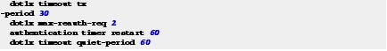
Step 3![]() Set the timers on the appropriate interfaces.
Set the timers on the appropriate interfaces.
These timers and variables control IEEE 802.1x authenticator operations when end devices stop functioning during authentication.
Begin in interface configuration mode.

For detailed information about the IEEE 802.1x timers and variables, see the Wired 802.1x Deployment Guide.
Step 4![]() Enable MAC authentication bypass (MAB) from interface configuration mode to authenticate supplicants that do not support IEEE 802.1x authentication.
Enable MAC authentication bypass (MAB) from interface configuration mode to authenticate supplicants that do not support IEEE 802.1x authentication.
When MAB is enabled, the switch uses the MAC address of the device as its identity. The authentication has a database of MAC addresses that are allowed network access.
We recommend that you enable MAB to support non-802.1x-compliant devices. MAB also is an alternate authentication method when end devices fail IEEE 802.1x authentication due to restricted ACL access.
Begin in interface configuration mode.

Step 5![]() Configure IEEE 802.1x on the appropriate interfaces.
Configure IEEE 802.1x on the appropriate interfaces.
When you configure an IEEE 802.1x parameter on a port, a dot1x authenticator is automatically created on the port. When that occurs, the dot1x pae authenticator command must also be configured to ensure that the dot1x authentication will work on legacy configurations.
Begin in interface configuration mode:

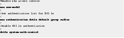
Step 6![]() Enable access control and IEEE 802.1x authentications.
Enable access control and IEEE 802.1x authentications.
Begin in global configuration mode.
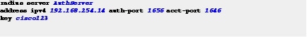
Step 7![]() To establish the radius server, configure the RADIUS server with IP address, UDP port for authentication and accounting server, and server encryption key.
To establish the radius server, configure the RADIUS server with IP address, UDP port for authentication and accounting server, and server encryption key.
Provision in Monitor Mode
Monitor mode enables IEEE 802.1x authentication without impacting the access of the end devices (supplicants) to a switch (authenticator). This mode allows you to continuously gather the following types of data for all the devices connected to your network:
- List of IEEE 802.1x-capable devices
- List of devices that are not capable of IEEE 802.1x
- Devices with good credentials
- Devices with bad credentials.
- List of valid MAC addresses (for MAB)
- List of unknown or invalid MAC addresses (for MAB)
We recommend monitor mode as a first-phase approach to provide secure access with IEEE 802.1x. Although this mode authenticates the end devices and users (supplicants), traffic is not impacted if authentication fails.
In monitor mode, IEEE 802.1x and MAB are enabled, but access is open to all users.
Step 8![]() To allow hosts to gain access to a controlled port, configure multi-authentication host mode and open authentication.
To allow hosts to gain access to a controlled port, configure multi-authentication host mode and open authentication.

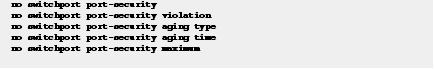
Step 9![]() Disable the Port Security feature, because when IEEE 802.1x is enabled, the Port Security feature becomes redundant and might interfere with the IEEE 802.1x functionality.
Disable the Port Security feature, because when IEEE 802.1x is enabled, the Port Security feature becomes redundant and might interfere with the IEEE 802.1x functionality.
Begin in interface configuration mode.
Provision in Low-Impact Mode
The next deployment phase in securing your network is to provision in low impact mode, which allows differentiated network access to authenticated users while permitting basic network services for all users.
Note![]() For information about configuration of multiple-authentication mode on IEEE 802.1x ports, see “Provision Common Wired Security Access”.
For information about configuration of multiple-authentication mode on IEEE 802.1x ports, see “Provision Common Wired Security Access”.
Minimize the impact to your initial network access settings and add differentiated network access to authenticated users with low-impact mode provisioning. In low-impact mode, authentication is open and network access is contained using less restrictive port ACLs. After authentication, dACLs are used to allow full network access to end devices.
Step 10![]() configure multi-domain mode to prevent unauthorized users from accessing an interface after an authorized user has been authenticated.
configure multi-domain mode to prevent unauthorized users from accessing an interface after an authorized user has been authenticated.

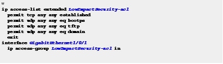
Step 11![]() Add a static ACL to allow basic network access.
Add a static ACL to allow basic network access.
Configure a restrictive port ACL that allows access for configuration and a Configured Trust List (CTL).
Begin in global configuration mode.
Provision in High-Impact Mode
The final deployment phase of securing your wired network is high-impact mode.
This phase goes beyond low-impact mode and provisions tight access control on the network port by configuring the default IEEE 802.1x authentication mode with dynamic VLAN for differentiated access.
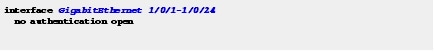
Step 12![]() Configure multi-authentication host mode, and open authentication.
Configure multi-authentication host mode, and open authentication.

Step 13![]() Disable RADIUS for this deployment phase.
Disable RADIUS for this deployment phase.
High-impact mode provides no network access to devices and users that fail authentication. In monitor mode and low-impact mode, we recommend that you identify and resolve the devices and user accounts that have failed authentication. Transition to high-impact mode when you are confident that end devices (that need network access) authenticate successfully, and authentication fails for devices and users that do not need access.
Begin in global configuration mode.
Step 14![]() Assign critical VLAN assignments for situations where the authentication server is unavailable.
Assign critical VLAN assignments for situations where the authentication server is unavailable.
The following command is used to configure a port to send both new and existing hosts to the critical VLAN when the RADIUS server is unavailable. Use this command for ports in multiple authentication (multiauth) mode or if the voice domain of the port is in MDA mode.

Step 15![]() If the authentication server does not respond, authorize voice.
If the authentication server does not respond, authorize voice.

Show Running Configuration for Provisioning Modes
Step 1![]() Enter the show running-configuration command to display provisioning modes for the switch.
Enter the show running-configuration command to display provisioning modes for the switch.
Figure 10 show running-configuration command for Provision in Monitor Mode
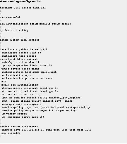
Figure 11 how running-configuration command for Provision in Low-Impact Mode
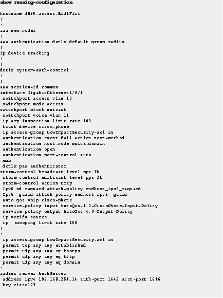
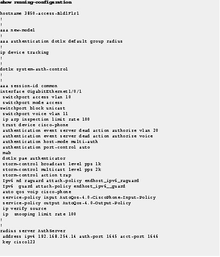
Figure 12 how running-configuration command for Provision in High-Impact Mode
Monitoring IEEE 802.1x Status and Statistics
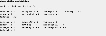
Step 1![]() Use the show dot1x statistics command to display switch-related and port-related IEEE 802.1x statistics.
Use the show dot1x statistics command to display switch-related and port-related IEEE 802.1x statistics.
To detect errors, filter the dot1x verbose messages that are enabled by default.
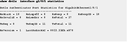
Step 2![]() Use the show dot1x interface statistics command to display IEEE 802.1x statistics for a specific port.
Use the show dot1x interface statistics command to display IEEE 802.1x statistics for a specific port.
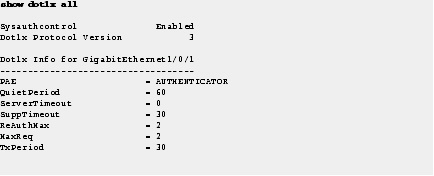
Step 3![]() Use the show dot1x all command to display the IEEE 802.1x administrative and operational status for a switch.
Use the show dot1x all command to display the IEEE 802.1x administrative and operational status for a switch.
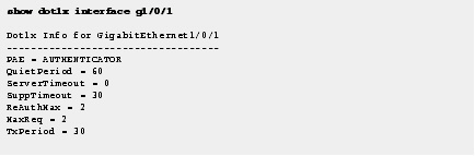
Step 4![]() Use the show dot1x interface command to display the IEEE 802.1x administrative and operational status for a specific port.
Use the show dot1x interface command to display the IEEE 802.1x administrative and operational status for a specific port.
 Feedback