Routing Configuration Guide, Cisco IOS Release 15.2(2)E (Catalyst 2960-X Switch)
Bias-Free Language
The documentation set for this product strives to use bias-free language. For the purposes of this documentation set, bias-free is defined as language that does not imply discrimination based on age, disability, gender, racial identity, ethnic identity, sexual orientation, socioeconomic status, and intersectionality. Exceptions may be present in the documentation due to language that is hardcoded in the user interfaces of the product software, language used based on RFP documentation, or language that is used by a referenced third-party product. Learn more about how Cisco is using Inclusive Language.
- Updated:
- June 27, 2014
Chapter: Configuring IP Unicast Routing
Configuring IP Unicast Routing
- Finding Feature Information
- Information About Configuring IP Unicast Routing
- Information About IP Routing
- Configuring IP Unicast Routing
- Enabling IP Unicast Routing
- Assigning IP Addresses to SVIs
- Configuring Static Unicast Routes
- Monitoring and Maintaining the IP Network
Finding Feature Information
Your software release may not support all the features documented in this module. For the latest caveats and feature information, see Bug Search Tool and the release notes for your platform and software release. To find information about the features documented in this module, and to see a list of the releases in which each feature is supported, see the feature information table at the end of this module.
Use Cisco Feature Navigator to find information about platform support and Cisco software image support. To access Cisco Feature Navigator, go to http://www.cisco.com/go/cfn. An account on Cisco.com is not required.
Information About Configuring IP Unicast Routing
This module describes how to configure IP Version 4 (IPv4) unicast routing on the switch.
A switch stack operates and appears as a single router to the rest of the routers in the network. .
 Note | In addition to IPv4 traffic, you can also enable IP Version 6 (IPv6) unicast routing and configure interfaces to forward IPv6 traffic. |
Information About IP Routing
In some network environments, VLANs are associated with individual networks or subnetworks. In an IP network, each subnetwork is mapped to an individual VLAN. Configuring VLANs helps control the size of the broadcast domain and keeps local traffic local. However, network devices in different VLANs cannot communicate with one another without a Layer 3 device (router) to route traffic between the VLAN, referred to as inter-VLAN routing. You configure one or more routers to route traffic to the appropriate destination VLAN.
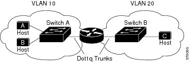
When Host A in VLAN 10 needs to communicate with Host B in VLAN 10, it sends a packet addressed to that host. Switch A forwards the packet directly to Host B, without sending it to the router.
When Host A sends a packet to Host C in VLAN 20, Switch A forwards the packet to the router, which receives the traffic on the VLAN 10 interface. The router checks the routing table, finds the correct outgoing interface, and forwards the packet on the VLAN 20 interface to Switch B. Switch B receives the packet and forwards it to Host C.
Types of Routing
Routers and Layer 3 switches can route packets in these ways:
The switch supports static routes and default routes, It does not support routing protocols.
IP Routing and Switch Stacks
A switch stack appears to the network as a single switch, regardless of which switch in the stack is connected to a routing peer.
The active switch performs these functions:
-
It generates, maintains, and distributes the distributed Cisco Express Forwarding (dCEF) database to all stack members. The routes are programmed on all switches in the stack bases on this database.
-
The MAC address of the active switch is used as the router MAC address for the whole stack, and all outside devices use this address to send IP packets to the stack.
-
All IP packets that require software forwarding or processing go through the CPU of the active switch.
Stack members perform these functions:
-
They act as routing standby switches, ready to take over in case they are elected as the new active switch if the active switch fails.
If a active switch fails, the stack detects that the active switch is down and elects one of the stack members to be the new active switch. During this period, except for a momentary interruption, the hardware continues to forward packets with no active protocols.
Upon election, the new active switch performs these functions:
-
It starts generating, receiving, and processing routing updates.
-
It builds routing tables, generates the CEF database, and distributes it to stack members.
-
It uses its MAC address as the router MAC address. To notify its network peers of the new MAC address, it periodically (every few seconds for 5 minutes) sends a gratuitous ARP reply with the new router MAC address.
-
It attempts to determine the reachability of every proxy ARP entry by sending an ARP request to the proxy ARP IP address and receiving an ARP reply. For each reachable proxy ARP IP address, it generates a gratuitous ARP reply with the new router MAC address. This process is repeated for 5 minutes after a new active switch election.

Caution
Partitioning of the switch stack into two or more stacks might lead to undesirable behavior in the network.
If the switch is reloaded, then all the ports on that switch go down and there is a loss of traffic for the interfaces involved in routing.
Configuring IP Unicast Routing
By default, IP routing is disabled on the switch. For detailed IP routing configuration information, see the Cisco IOS IP Configuration Guide, Release 12.2 from the Cisco.com page under Documentation > Cisco IOS Software Releases > 12.2 Mainline > Configuration Guides.
In these procedures, the specified interface must be a switch virtual interface (SVI)-a VLAN interface created by using the interface vlanvlan_id global configuration command and by default a Layer 3 interface. All Layer 3 interfaces on which routing will occur must have IP addresses assigned to them. See the Assigning IP Addresses to SVIs section .
Note | The switch supports 16 static routes (including user-configured routes and the default route) and any directly connected routes and default routes for the management interface. You can use the "lanbase-default" SDM template to configure the static routes. The switch can have an IP address assigned to each SVI. Before enabling routing, enter the sdm prefer lanbase-routing global configuration command and reload the switch. |
Procedures for configuring routing:
Enabling IP Unicast Routing
By default, the Switch is in Layer 2 switching mode and IP routing is disabled. To use the Layer 3 capabilities of the Switch, you must enable IP routing.
Assigning IP Addresses to SVIs
To configure IP routing, you need to assign IP addresses to Layer 3 network interfaces. This enables communication with the hosts of those interfaces that use IP. IP routing is disabled by default, and no IP addresses are assigned to SVIs.
An IP address identifies a location to which IP packets can be sent. Some IP addresses are reserved for special uses and cannot be used for host, subnet, or network addresses. RFC 1166, “Internet Numbers,” contains the official description of IP addresses.
An interface can have one primary IP address. A mask identifies the bits that denote the network number in an IP address. When you use the mask to subnet a network, the mask is referred to as a subnet mask. To receive an assigned network number, contact your Internet service provider.
Follow these steps to assign an IP address and a network mask to an SVI:
Configuring Static Unicast Routes
Static unicast routes are user-defined routes that cause packets moving between a source and a destination to take a specified path. Static routes can be important if the router cannot build a route to a particular destination and are useful for specifying a gateway of last resort to which all unroutable packets are sent.
Follow these steps to configure a static route:
Use the no ip route prefix mask {address| interface} global configuration command to remove a static route. The switch retains static routes until you remove them.
Monitoring and Maintaining the IP Network
You can remove all contents of a particular cache, table, or database. You can also display specific statistics.
 Feedback