Release Notes for the Catalyst 3560-C Switch, Cisco IOS Release 12.2(55)EX and Later
Available Languages
Table of Contents
Release Notes for the Catalyst 3560-C Switch, Cisco IOS Release 12.2(55)EX and Later
Device Manager System Requirements
Finding the Software Version and Feature Set
Upgrading a Switch by Using the Device Manager
Upgrading a Switch by Using the CLI
Recovering from a Software Failure
Resolved Caveats in Cisco IOS Release 12.2(55)EX and Later
Updates to the Catalyst 3560-C and 2960-C Switch Hardware Documentation
Update to the Catalyst 3560-C and 2960-C Switch Getting Started Guide
Catalyst 3560-C Updates to the Catalyst 3560 Switch Software Configuration Guide
POE, Power Monitoring, and Power Policing
PoE+ Uplinks and PoE Pass-Through Capability
Understanding Media Access Control Security and MACsec Key Agreement
Catalyst 3560-C Updates to the Catalyst 3560 Switch Command Reference
authentication event linksec fail action
clear macsec counters interface
mka policy (global configuration)
mka policy (interface configuration)
show controllers ethernet phy macsec
Obtaining Documentation and Submitting a Service Request
Release Notes for the Catalyst 3560-C Switch, Cisco IOS Release 12.2(55)EX and Later
Cisco IOS Release 12.2(55)EX3 runs on all Catalyst 3560-C compact switches. See Table 1 to see the minimum Cisco IOS release required by the different switches.
These release notes include important information about Cisco IOS Release 12.2(55)EX and later and any limitations, restrictions, and caveats that apply to the releases. Verify that these release notes are correct for your switch:
- If you are installing a new switch, see the Cisco IOS release label on the rear panel of your switch.
- If your switch is on, use the show version privileged EXEC command. See the “Finding the Software Version and Feature Set” section.
- If you are upgrading to a new release, see the software upgrade filename for the software version. See the “Deciding Which Files to Use” section.
You can download the switch software from this site (registered Cisco.com users with a login password):
http://www.cisco.com/cisco/web/download/index.html
The Catalyst 3560-C universal image is an IP base image. Unless otherwise indicated, the software supports all features that are supported by the Catalyst 3560 IP base image in Cisco IOS Release 12.2(55)SE and that are described in the Catalyst 3560 software configuration guide and command reference.

Note![]() For additional features and a list of Catalyst 3560 features that are not supported, see the “Catalyst 3560-C Features” section.
For additional features and a list of Catalyst 3560 features that are not supported, see the “Catalyst 3560-C Features” section.
For basic configuration and command information, see the configuration guide and command reference for the Catalyst 3560 switch for Cisco IOS Release 12.2(55)SE on Cisco.com:
http://www.cisco.com/en/US/products/hw/switches/ps5528/tsd_products_support_series_home.html
Catalyst 3560-C Features
Unless otherwise indicated, the Catalyst 3560-C switches supports all features that are supported by the Catalyst 3560 IP base image in Cisco IOS Release 12.2(55)SE, including these applications:
- Smart Install—The switch can operate as a Smart Install director. See the Smart Install Configuration Guide for more information:
http://www.cisco.com/en/US/docs/switches/lan/smart_install/release_12.2_55_se/configuration/guide/smart_install3.html - EnergyWise—The switch supports EnergyWise phase 2. See the EnergyWise Configuration Guide at
http://www.cisco.com/en/US/docs/switches/lan/energywise/phase2/ios/configuration/guide/ew_v2.html
and the release notes at:
http://www.cisco.com/en/US/docs/switches/lan/energywise/phase2/ios/release/notes/OL19810.html
The Catalyst 3560-C compact switches also support these features that are not supported on
Catalyst 3560 switches in Cisco IOS Release 12.2(55)SE:
- USB mini-type B console port and USB type A port
- Support for PoE+, power sensing, and power policing
- The Catalyst 3560CPD-8PT switches also support PoE pass-through. See the “PoE+ Uplinks and PoE Pass-Through Capability” section.
- Support for Media Access Control Security (MACsec)
- Support for IPv6 MIBs (Cisco-IEFT-IP-MIB and Cisco-IEFT-IP-Forwarding-MIB) and PoE policing MIB
- Support for a different switch database management (SDM) template than the Catalyst 3560 switch.
See the “Documentation Updates” section for configuration and commands for these features.
The Catalyst 3560-C does not support the IP services image.
Note![]() Do not activate the demonstration license for IP services on the switch, as it is not supported by Cisco.
Do not activate the demonstration license for IP services on the switch, as it is not supported by Cisco.
It also does not support these features that are supported in the Catalyst 3560 IP base image:
System Requirements
Supported Hardware
8 10/100/1000 PoE+1 ports 2 dual-purpose uplink ports (each dual-purpose port has 1 10/100/1000BASE-T copper port and 1 SFP2 module slot) |
||
SFP3 modules |
GLC-FE-(100FX,100LX,100BX-D, 100BX-U) For complete lists of supported SFP modules, see the hardware installation guide and the documents on this page: http://www.cisco.com/en/US/products/hw/modules/ps5455/products_device_support_tables_list.html |
Upgrading the Switch Software
- Finding the Software Version and Feature Set
- Deciding Which Files to Use
- Archiving Software Images
- Upgrading a Switch by Using the CLI
- Recovering from a Software Failure
Finding the Software Version and Feature Set
The Cisco IOS image is stored as a bin file in a directory that is named with the Cisco IOS release. A subdirectory contains the files needed for web management. The image is stored on the system board flash device (flash:).
Note![]() For the Catalyst 3560-C, the tar file is c3560c-universalk9-tar.122-55.EX3.tar and the bin file is c3560c405ex-univsalk9-bin.122-55.EX.bin.
For the Catalyst 3560-C, the tar file is c3560c-universalk9-tar.122-55.EX3.tar and the bin file is c3560c405ex-univsalk9-bin.122-55.EX.bin.
You can use the show version privileged EXEC command to see the software version that is running on your switch. The second line of the display shows the version.
You can also use the dir filesystem : privileged EXEC command to see the directory names of other software images that you might have stored in flash memory.
Deciding Which Files to Use
The upgrade procedures in these release notes describe how to perform the upgrade by using a combined tar file. This file contains the Cisco IOS image file and the files needed for the embedded device manager. You must use the combined tar file to upgrade the switch through the device manager. To upgrade the switch through the CLI, use the tar file and the archive download-sw privileged EXEC command.
Catalyst 3560-C switches running payload-encryption images can encrypt management and data traffic. Switches running nonpayload-encryption images can encrypt only management traffic, such as a Secure Shell (SSH) management session.
- Management traffic is encrypted when SSH, Secure Socket Layer (SSL), Simple Network Management Protocol (SNMP), and other cryptographic-capable applications or protocols are enabled.
- Data traffic is encrypted when MACsec is enabled.
Archiving Software Images
Before upgrading your switch software, make sure that you have archived copies of the current Cisco IOS release and the Cisco IOS release to which you are upgrading. You should keep these archived images until you have upgraded all devices in the network to the new Cisco IOS image and until you have verified that the new Cisco IOS image works properly in your network.
Cisco routinely removes old Cisco IOS versions from Cisco.com. See Product Bulletin 2863 for more information:
http://www.cisco.com/en/US/prod/collateral/iosswrel/ps8802/ps6969/ps1835/
prod_bulletin0900aecd80281c0e.html
You can copy the bin software image file on the flash memory to the appropriate TFTP directory on a host by using the copy flash: tftp: privileged EXEC command.
Note![]() Although you can copy any file on the flash memory to the TFTP server, it is time-consuming to copy all of the HTML files in the tar file. We recommend that you download the tar file from Cisco.com and archive it on an internal host in your network.
Although you can copy any file on the flash memory to the TFTP server, it is time-consuming to copy all of the HTML files in the tar file. We recommend that you download the tar file from Cisco.com and archive it on an internal host in your network.
You can also configure the switch as a TFTP server to copy files from one switch to another without using an external TFTP server by using the tftp-server global configuration command. For more information about the tftp-server command, see the “Basic File Transfer Services Commands” section of the Cisco IOS Configuration Fundamentals Command Reference, Release 12.2 :
http://www.cisco.com/en/US/docs/ios/fundamentals/command/reference/cf_t1.html
Upgrading a Switch by Using the Device Manager
You can upgrade switch software by using the device manager. For detailed instructions, click Help.
Note![]() When using the device manager to upgrade your switch, do not use or close your browser session after the upgrade process begins. Wait until after the upgrade process completes.
When using the device manager to upgrade your switch, do not use or close your browser session after the upgrade process begins. Wait until after the upgrade process completes.
Upgrading a Switch by Using the CLI
This procedure is for copying the combined tar file to the switch. You copy the file to the switch from a TFTP server and extract the files. You can download an image file and replace or keep the current image.
To download software, follow these steps:
Step 1![]() Use Table 4 to identify the file that you want to download.
Use Table 4 to identify the file that you want to download.
Step 2![]() Download the software image file:
Download the software image file:
a.![]() If you are a registered customer, go to this URL and log in.
If you are a registered customer, go to this URL and log in.
http://www.cisco.com/cisco/web/download/index.html
b.![]() Navigate to Switches > LAN Switches - Access.
Navigate to Switches > LAN Switches - Access.
c.![]() Navigate to your switch model.
Navigate to your switch model.
d.![]() Click IOS Software, and select the latest IOS release.
Click IOS Software, and select the latest IOS release.
Download the image that you identified in Step 1.
Step 3![]() Copy the image to the appropriate TFTP directory on the workstation, and make sure that the TFTP server is properly configured.
Copy the image to the appropriate TFTP directory on the workstation, and make sure that the TFTP server is properly configured.
For more information, see Appendix B in the software configuration guide for this release.
Step 4![]() Log into the switch through the console port or a Telnet session.
Log into the switch through the console port or a Telnet session.
Step 5![]() (Optional) Ensure that you have IP connectivity to the TFTP server by entering this privileged EXEC command:
(Optional) Ensure that you have IP connectivity to the TFTP server by entering this privileged EXEC command:
For more information about assigning an IP address and default gateway to the switch, see the software configuration guide for this release.
Step 6![]() Download the image file from the TFTP server to the switch. If you are installing the same software version that is currently on the switch, overwrite the current image by entering this privileged EXEC command:
Download the image file from the TFTP server to the switch. If you are installing the same software version that is currently on the switch, overwrite the current image by entering this privileged EXEC command:
The /overwrite option overwrites the software image in flash memory with the downloaded one.
The /reload option reloads the system after downloading the image unless the configuration has been changed and not saved.
For // location, specify the IP address of the TFTP server.
For / directory / image-name .tar, specify the directory (optional) and the image to download. Directory and image names are case sensitive.
This example shows how to download an image from a TFTP server at 198.30.20.19 and to overwrite the image on the switch:
You can also download the image file from the TFTP server to the switch and keep the current image by replacing the /overwrite keywords with the /leave-old-sw keywords.
Installation Notes
Use these methods to assign IP information to your switch:
- The Express Setup program, as described in the switch getting started guide.
- The CLI-based setup program, as described in the switch hardware installation guide.
- The DHCP-based autoconfiguration, as described in the switch software configuration guide.
- Manually assigning an IP address, as described in the switch software configuration guide.
Limitations and Restrictions
You should review this section before you begin working with the switch. These are known limitations that will not be fixed, and there is not always a workaround. Some features might not work as documented, and some features could be affected by recent changes to the switch hardware or software.
Configuration
This problem occurs under these conditions:
–![]() When the switch is booted up without a configuration (no config.text file in flash memory).
When the switch is booted up without a configuration (no config.text file in flash memory).
–![]() When the switch is connected to a DHCP server that is configured to give it an address (the dynamic IP address is assigned to VLAN 1).
When the switch is connected to a DHCP server that is configured to give it an address (the dynamic IP address is assigned to VLAN 1).
–![]() When an IP address is configured on VLAN 1 before the dynamic address lease assigned to VLAN 1 expires.
When an IP address is configured on VLAN 1 before the dynamic address lease assigned to VLAN 1 expires.
The workaround is to reconfigure the static IP address. (CSCea71176 and CSCdz11708)
- When you change a port from a nonrouted port to a routed port or the reverse, the applied auto-QoS setting is not changed or updated when you verify it by using the show running interface or show mls qos interface user EXEC commands. These are the workarounds:
1. Disable auto-QoS on the interface.
2. Change the routed port to a nonrouted port or the reverse.
3. Re-enable auto-QoS on the interface. (CSCec44169)
- The DHCP snooping binding database is not written to flash memory or a remote file in any of these situations:
–![]() The DHCP snooping database file is manually removed from the file system. After enabling the DHCP snooping database by configuring a database URL, a database file is created. If the file is manually removed from the file system, the DHCP snooping database does not create another database file. You need to disable the DHCP snooping database and enable it again to create the database file.
The DHCP snooping database file is manually removed from the file system. After enabling the DHCP snooping database by configuring a database URL, a database file is created. If the file is manually removed from the file system, the DHCP snooping database does not create another database file. You need to disable the DHCP snooping database and enable it again to create the database file.
–![]() The URL for the configured DHCP snooping database was replaced because the original URL was not accessible. The new URL might not take effect after the timeout of the old URL.
The URL for the configured DHCP snooping database was replaced because the original URL was not accessible. The new URL might not take effect after the timeout of the old URL.
No workaround is necessary; these are the designed behaviors. (CSCed50819)
- When dynamic ARP inspection is enabled on a switch or switch stack, ARP and RARP packets greater than 2016 bytes are dropped by the switch or switch stack. This is a hardware limitation.
However, when dynamic ARP inspection is not enabled and a jumbo MTU is configured, ARP and RARP packets are correctly bridged in hardware. (CSCed79734)
- When connected to some third-party devices that send early preambles, a switch port operating at 100 Mb/s full duplex or 100 Mb/s half duplex might bounce the line protocol up and down. The problem is observed only when the switch is receiving frames.
The workaround is to configure the port for 10 Mb/s and half duplex or to connect a hub or a nonaffected device to the switch. (CSCed39091)
- When port security is enabled on an interface in restricted mode and the switchport block unicast interface command has been entered on that interface, MAC addresses are incorrectly forwarded when they should be blocked
The workaround is to enter the no switchport block unicast interface configuration command on that specific interface. (CSCee93822)
There is no workaround. This is a cosmetic error and does not affect the functionality of the switch. (CSCef59331)
- The switch might display tracebacks similar to this example when an EtherChannel interface port-channel type changes from Layer 2 to Layer 3 or the reverse:
15:50:11: %COMMON_FIB-4-FIBNULLHWIDB: Missing hwidb for fibhwidb Port-channel1 (ifindex 1632) -Traceback= A585C B881B8 B891CC 2F4F70 5550E8 564EAC 851338 84AF0C 4CEB50 859DF4 A7BF28 A98260 882658 879A58
The workaround is to configure aggressive UDLD. (CSCsh70244).
- When you enter the boot host retry timeout global configuration command to specify the amount of time that the client should keep trying to download the configuration and you do not enter a timeout value, the default value is zero, which should mean that the client keeps trying indefinitely. However, the client does not keep trying to download the configuration.
The workaround is to always enter a nonzero value for the timeout value when you enter the boot host retry timeout timeout-value command. (CSCsk65142)
Ethernet
- Traffic on EtherChannel ports is not perfectly load-balanced. Egress traffic on EtherChannel ports are distributed to member ports on load balance configuration and traffic characteristics like MAC or IP address. More than one traffic stream may map to same member ports based on hashing results calculated by the ASIC.
If this happens, uneven traffic distribution occurs on EtherChannel ports.
Changing the load balance distribution method or changing the number of ports in the EtherChannel can resolve this problem. Use any of these workarounds to improve EtherChannel load balancing:
–![]() for random source-ip and dest-ip traffic, configure load balance method as src-dst-ip
for random source-ip and dest-ip traffic, configure load balance method as src-dst-ip
–![]() for incrementing source-ip traffic, configure load balance method as src-ip
for incrementing source-ip traffic, configure load balance method as src-ip
–![]() for incrementing dest-ip traffic, configure load balance method as dst-ip
for incrementing dest-ip traffic, configure load balance method as dst-ip
–![]() Configure the number of ports in the EtherChannel so that the number is equal to a power of 2 (i.e. 2, 4, or 8)
Configure the number of ports in the EtherChannel so that the number is equal to a power of 2 (i.e. 2, 4, or 8)
For example, with load balance configured as dst-ip with 150 distinct incrementing destination IP addresses, and the number of ports in the EtherChannel set to either 2, 4, or 8, load distribution is optimal.(CSCeh81991)
Fallback Bridging
- If a bridge group contains a VLAN to which a static MAC address is configured, all non-IP traffic in the bridge group with this MAC address destination is sent to all ports in the bridge group. The workaround is to remove the VLAN from the bridge group or to remove the static MAC address from the VLAN. (CSCdw81955)
- Known unicast (secured) addresses are flooded within a bridge group if secure addresses are learned or configured on a port and the VLAN on this port is part of a bridge group. Non-IP traffic destined to the secure addresses is flooded within the bridge group. The workaround is to disable fallback bridging or to disable port security on all ports in all VLANs participating in fallback bridging. To remove an interface from a bridge group and to remove the bridge group, use the no bridge-group bridge-group interface configuration command. To disable port security on all ports in all VLANs participating in fallback bridging, use the no switchport port-security interface configuration command. (CSCdz80499)
HSRP
- When the active switch fails in a switch cluster that uses HSRP redundancy, the new active switch might not contain a full cluster member list. The workaround is to ensure that the ports on the standby cluster members are not in the spanning-tree blocking state. To verify that these ports are not in the blocking state, see the “Configuring STP” chapter in the software configuration guide. (CSCec76893)
IP
- The switch does not create an adjacent table entry when the ARP timeout value is 15 seconds and the ARP request times out. The workaround is to not set an ARP timeout value lower than 120 seconds. (CSCea21674)
- When the rate of received DHCP requests exceeds 2,000 packets per minute for a long time, the response time might be slow when you are using the console. The workaround is to use rate limiting on DHCP traffic to prevent a denial of service attack from occurring. (CSCeb59166)
IP Telephony
- After you change the access VLAN on a port that has IEEE 802.1x enabled, the IP phone address is removed. Because learning is restricted on IEEE 802.1x-capable ports, it takes approximately 30 seconds before the address is relearned. No workaround is necessary. (CSCea85312)
- (PoE-capable switches) The switch uses the IEEE classification to learn the maximum power consumption of a powered device before powering it. The switch grants power only when the maximum wattage configured on the port is less than or equal to the IEEE class maximum. This ensures that the switch power budget is not oversubscribed. There is no such mechanism in Cisco prestandard powered devices.
The workaround for networks with prestandard powered devices is to leave the maximum wattage set at the default value (15.4 W). You can also configure the maximum wattage for the port for no less than the value the powered device reports as the power consumption through CDP messages. For networks with IEEE Class 0, 3, or 4 devices, do not configure the maximum wattage for the port at less than the default 15.4 W (15,400 milliwatts). (CSCee80668)
- Some access point devices are incorrectly discovered as IEEE 802.3af Class 1 devices. These access points should be discovered as Cisco pre-standard devices. The show power inline user EXEC command shows the access point as an IEEE Class 1 device. The workaround is to power the access point by using an AC wall adaptor. (CSCin69533)
- The Cisco 7905 IP Phone is error-disabled when the phone is connected to wall power.
The workaround is to enable PoE and to configure the switch to recover from the PoE error-disabled state. (CSCsf32300)
Multicasting
- The switch does not support tunnel interfaces for unicast routed traffic. Only Distance Vector Multicast Routing Protocol (DVMRP) tunnel interfaces are supported for multicast routing.
- Nonreverse-path forwarded (RPF) IP multicast traffic to a group that is bridged in a VLAN is leaked onto a trunk port in the VLAN even if the port is not a member of the group in the VLAN, but it is a member of the group in another VLAN. Because unnecessary traffic is sent on the trunk port, it reduces the bandwidth of the port.
There is no workaround for this problem because non-RPF traffic is continuous in certain topologies. As long as the trunk port is a member of the group in at least one VLAN, this problem occurs for the non-RPF traffic. (CSCdu25219)
- If the number of multicast routes and Internet Group Management Protocol (IGMP) groups are more than the maximum number specified by the show sdm prefer global configuration command, the traffic received on unknown groups is flooded in the received VLAN even though the show ip igmp snooping multicast-table privileged EXEC command output shows otherwise.
The workaround is to reduce the number of multicast routes and IGMP snooping groups to less than the maximum supported value. (CSCdy09008)
- IGMP filtering is applied to packets that are forwarded through hardware. It is not applied to packets that are forwarded through software. Hence, with multicast routing enabled, the first few packets are sent from a port even when IGMP filtering is set to deny those groups on that port.
There is no workaround. (CSCdy82818)
- When you use the ip access-group interface configuration command with a router access control list (ACL) to deny access to a group in a VLAN, multicast data to the group that is received in the VLAN is always flooded in the VLAN, regardless of IGMP group membership in the VLAN. This provides reachability to directly connected clients, if any, in the VLAN.
The workaround is to not apply a router ACL set to deny access to a VLAN interface. Apply the security through other means; for example, apply VLAN maps to the VLAN instead of using a router ACL for the group. (CSCdz86110)
- If an IG MP report packet has two multicast group records, the switch removes or adds interfaces depending on the order of the records in the packet:
–![]() If the ALLOW_NEW_SOURCE record is before the BLOCK_OLD_SOURCE record, the switch removes the port from the group.
If the ALLOW_NEW_SOURCE record is before the BLOCK_OLD_SOURCE record, the switch removes the port from the group.
–![]() If the BLOCK_OLD_SOURCE record is before the ALLOW_NEW_SOURCE record, the switch adds the port to the group.
If the BLOCK_OLD_SOURCE record is before the ALLOW_NEW_SOURCE record, the switch adds the port to the group.
There is no workaround. (CSCec20128)
- When IGMP snooping is disabled and you enter the switchport block multicast interface configuration command, IP multicast traffic is not blocked.
The switchport block multicast interface configuration command is only applicable to non-IP multicast traffic.
There is no workaround. (CSCee16865)
–![]() You disable IP multicast routing or re-enable it globally on an interface.
You disable IP multicast routing or re-enable it globally on an interface.
–![]() A switch mroute table temporarily runs out of resources and recovers later.
A switch mroute table temporarily runs out of resources and recovers later.
The workaround is to enter the clear ip mroute privileged EXEC command on the interface. (CSCef42436)
After you configure a switch to join a multicast group by entering the ip igmp join-group group-address interface configuration command, the switch does not receive join packets from the client, and the switch port connected to the client is removed from the IGMP snooping forwarding table.
–![]() Cancel membership in the multicast group by using the no ip igmp join-group group-address interface configuration command on an SVI.
Cancel membership in the multicast group by using the no ip igmp join-group group-address interface configuration command on an SVI.
–![]() Disable IGMP snooping on the VLAN interface by using the no ip igmp snooping vlan vlan-id global configuration command. (CSCeh90425)
Disable IGMP snooping on the VLAN interface by using the no ip igmp snooping vlan vlan-id global configuration command. (CSCeh90425)
Power
- Entering the shutdown and the no shutdown interface configuration commands on the internal link can disrupt the PoE operation. If a new IP phone is added while the internal link is in shutdown state, the IP phone does not get inline power if the internal link is brought up within 5 minutes.
The workaround is to enter the shutdown and the no shutdown interface configuration commands on the Fast Ethernet interface of a new IP phone that is attached to the service module port after the internal link is brought up. (CSCeh45465)
QoS
- Some switch queues are disabled if the buffer size or threshold level is set too low with the mls qos queue-set output global configuration command. The ratio of buffer size to threshold level should be greater than 10 to avoid disabling the queue.
The workaround is to choose compatible buffer sizes and threshold levels. (CSCea76893)
- When auto-QoS is enabled on the switch, priority queuing is not enabled. Instead, the switch uses shaped round robin (SRR) as the queuing mechanism. The auto-QoS feature is designed on each platform based on the feature set and hardware limitations, and the queuing mechanism supported on each platform might be different.
There is no workaround. (CSCee22591)
- If you configure a large number of input interface VLANs in a class map, a traceback message similar to this might appear:
Routing
- The switch does not support tunnel interfaces for unicast routed traffic. Only Distance Vector Multicast Routing Protocol (DVMRP) tunnel interfaces are supported for multicast routing.
- A route map that has an ACL with a Differentiated Services Code Point (DSCP) clause cannot be applied to a Layer 3 interface. The switch rejects this configuration and displays a message that the route map is unsupported.
Smart Install
- Backing up a Smart Install configuration could fail if the backup repository is a Windows server and the backup file already exists in the server.
The workaround is to use the TFTP utility of another server instead of a Windows server or to manually delete the existing backup file before backing up again. (CSCte53737)
- In a Smart Install network with the backup feature enabled (the default), the director sends the backup configuration file to the client during zero-touch replacement. However, when the client is a switch in a stack, the client receives the seed file from the director instead of receiving the backup configuration file.
The workaround, if you need to configure a switch in a stack with the backup configuration, is to use the vstack download config privileged EXEC command so that the director performs an on-demand upgrade on the client.
–![]() When the backup configuration is stored in a remote repository, enter the location of the repository.
When the backup configuration is stored in a remote repository, enter the location of the repository.
–![]() When the backup file is stored in the director flash memory, you must manually set the permissions for the file before you enter the vstack download config command. (CSCtf18775)
When the backup file is stored in the director flash memory, you must manually set the permissions for the file before you enter the vstack download config command. (CSCtf18775)
- If the director in the Smart Install network is located between an access point and the DHCP server, the access point tries to use the Smart Install feature to upgrade even though access points are not supported devices. The upgrade fails because the director does not have an image and configuration file for the access point.
There is no workaround. (CSCtg98656)
- When a Smart Install director is upgrading a client switch that is not Smart Install-capable (that is, not running Cisco IOS Release 12.2(52)SE or later), the director must enter the password configured on the client switch. If the client switch does not have a configured password, there are unexpected results depending on the software release running on the client:
–![]() When you select the NONE option in the director CLI, the upgrade should be allowed and is successful on client switches running Cisco IOS Release 12.2(25)SE through 12.2(46)SE, but fails on clients running Cisco IOS Release 12.2(50)SE through 12.2(50)SEx.
When you select the NONE option in the director CLI, the upgrade should be allowed and is successful on client switches running Cisco IOS Release 12.2(25)SE through 12.2(46)SE, but fails on clients running Cisco IOS Release 12.2(50)SE through 12.2(50)SEx.
–![]() When you enter any password in the director CLI, the upgrade should not be allowed, but it is successful on client switches running Cisco IOS Release 12.2(25)SE through 12.2(46)SE, but fails on clients running Cisco IOS Release 12.2(50)SE through 12.2(50)SEx.
When you enter any password in the director CLI, the upgrade should not be allowed, but it is successful on client switches running Cisco IOS Release 12.2(25)SE through 12.2(46)SE, but fails on clients running Cisco IOS Release 12.2(50)SE through 12.2(50)SEx.
SPAN and RSPAN
- The egress SPAN data rate might degrade when fallback bridging or multicast routing is enabled. The amount of degradation depends on the processor loading. Typically, the switch can egress SPAN at up to 40,000 packets per second (64-byte packets). As long as the total traffic being monitored is below this limit, there is no degradation. However, if the traffic being monitored exceeds the limit, only a portion of the source stream is spanned. When this occurs, the following console message appears:
Decreased egress SPAN rate. In all cases, normal traffic is not affected; the degradation limits only how much of the original source stream can be egress spanned. If fallback bridging and multicast routing are disabled, egress SPAN is not degraded.
There is no workaround. If possible, disable fallback bridging and multicast routing. If possible, use ingress SPAN to observe the same traffic. (CSCeb01216)
- Some IGMP report and query packets with IP options might not be ingress-spanned. Packets that are susceptible to this problem are IGMP packets containing 4 bytes of IP options (IP header length of 24). An example of such packets would be IGMP reports and queries having the router alert IP option. Ingress-spanning of such packets is not accurate and can vary with the traffic rate. Typically, very few or none of these packets are spanned.
There is no workaround. (CSCeb23352)
- Cisco Discovery Protocol (CDP), VLAN Trunking Protocol (VTP), and Port Aggregation Protocol (PAgP) packets received from a SPAN source are not sent to the destination interfaces of a local SPAN session.
The workaround is to use the monitor session session_number destination { interface interface-id encapsulation replicate} global configuration command for local SPAN. (CSCed24036)
Trunking
- The switch treats frames received with mixed encapsulation (IEEE 802.1Q and Inter-Switch Link [ISL]) as frames with FCS errors, increments the error counters, and the port LED blinks amber. This happens when an ISL-unaware device receives an ISL-encapsulated packet and forwards the frame to an IEEE 802.1Q trunk interface.
There is no workaround. (CSCdz33708)
- IP traffic with IP options set is sometimes leaked on a trunk port. For example, a trunk port is a member of an IP multicast group in VLAN X but is not a member in VLAN Y. If VLAN Y is the output interface for the multicast route entry assigned to the multicast group and an interface in VLAN Y belongs to the same multicast group, the IP-option traffic received on an input VLAN interface other than one in VLAN Y is sent on the trunk port in VLAN Y because the trunk port is forwarding in VLAN Y, even though the port has no group membership in VLAN Y.
There is no workaround. (CSCdz42909).
- For trunk ports or access ports configured with IEEE 802.1Q tagging, inconsistent statistics might appear in the show interfaces counters privileged EXEC command output. Valid IEEE 802.1Q frames of 64 to 66 bytes are correctly forwarded even though the port LED blinks amber, and the frames are not counted on the interface statistics.
VLAN
- If the number of VLANs times the number of trunk ports exceeds the recommended limit of 13,000, the switch can fail.
The workaround is to reduce the number of VLANs or trunks. (CSCeb31087)
- A CPUHOG message sometimes appears when you configure a private VLAN. Enable port security on one or more of the ports affected by the private VLAN configuration.
There is no workaround. (CSCed71422)
- When line rate traffic is passing through a dynamic port, and you enter the switchport access vlan dynamic interface configuration command for a range of ports, the VLANs might not be assigned correctly. One or more VLANs with a null ID appears in the MAC address table instead.
The workaround is to enter the switchport access vlan dynamic interface configuration command separately on each port. (CSCsi26392)
Important Notes
Cisco IOS Notes
- If the switch requests information from the Cisco Secure Access Control Server (ACS) and the message exchange times out because the server does not respond, a message similar to this appears:
If this message appears, check that there is network connectivity between the switch and the ACS. You should also check that the switch has been properly configured as an AAA client on the ACS.
Device Manager Notes
- You cannot create and manage switch clusters through the device manager. To create and manage switch clusters, use the CLI.
- For device manager session on Internet Explorer, popup messages in Japanese or in simplified Chinese can appear as garbled text. These messages appear properly if your operating system is in Japanese or Chinese.
- We recommend this browser setting to speed up the time needed to display the device manager from Microsoft Internet Explorer.
From Microsoft Internet Explorer:
1. Choose Tools > Internet Options.
2. Click Settings in the “Temporary Internet files” area.
3. From the Settings window, choose Automatically.
5. Click OK to exit the Internet Options window.
- The HTTP server interface must be enabled to display the device manager. By default, the HTTP server is enabled on the switch. Use the show running-config privileged EXEC command to see if the HTTP server is enabled or disabled.
Beginning in privileged EXEC mode, follow these steps to configure the HTTP server interface:
- The device manager uses the HTTP protocol (the default is port 80) and the default method of authentication (the enable password) to communicate with the switch through any of its Ethernet ports and to allow switch management from a standard web browser.
If you change the HTTP port, you must include the new port number when you enter the IP address in the browser Location or Address field (for example, http://10.1.126.45:184 where 184 is the new HTTP port number). You should write down the port number through which you are connected. Use care when changing the switch IP information.
If you are not using the default method of authentication (the enable password), you need to configure the HTTP server interface with the method of authentication used on the switch.
Beginning in privileged EXEC mode, follow these steps to configure the HTTP server interface authentication method:
Open Caveats
In a Smart Install network, when the director is connected between the client and the DHCP server and the server has options configured for image and configuration, then the client does not receive the image and configuration files sent by the DHCP server during an automatic upgrade. Instead the files are overwritten by the director, and the client receives the image and configuration that the director sends.
–![]() If client needs to upgrade using an image and configuration file configured in the DHCP server options, you should remove the client from the Smart Install network during the upgrade.
If client needs to upgrade using an image and configuration file configured in the DHCP server options, you should remove the client from the Smart Install network during the upgrade.
–![]() In a network using Smart Install, you should not configure options for image and configuration in the DHCP server. For clients to upgrade using Smart Install, you should configure product-id specific image and configuration files in the director.
In a network using Smart Install, you should not configure options for image and configuration in the DHCP server. For clients to upgrade using Smart Install, you should configure product-id specific image and configuration files in the director.
When ports in an EtherChannel are linking up, the message EC-5-CANNOT_BUNDLE2 might appear. This condition is often self-correcting, indicated by the appearance of an EC-5-COMPATIBLE message following the first message. On occasion, the issue does not self-correct, and the ports may remain unbundled.
The workaround is to reload the switch or to restore the EtherChannel bundle by shutting down and then enabling the member ports and the EtherChannel in this order:
–![]() Enter the shutdown interface configuration command on each member port.
Enter the shutdown interface configuration command on each member port.
–![]() Enter the shutdown command on the port-channel interface.
Enter the shutdown command on the port-channel interface.
–![]() Enter the no shutdown command on each member port.
Enter the no shutdown command on each member port.
–![]() Enter the no shutdown command on the port-channel interface.
Enter the no shutdown command on the port-channel interface.
When the Catalyst 3560-C switch is the multiple spanning tree protocol (MSTP) master switch with one or more MST client switches attached and you map VLANs to an MST instance using the instance instance_id vlan vlan-range MST configuration command on it, if you enter the no spanning-tree mode MST configuration command on a client switch to disable MST mode, then the client switch does not update its VLAN mapping back to the original state.
The workaround is to restart the switch.
If you use the manual bootloader to boot up the software using the switch: prompt on a WS-C3560CG-8TC-S, WS-C3560CG-8PC-S, or WS-C3560CPD-8PT-S switch, the console port LED might not light to indicate whether the RJ-45 or mini-USB console is being used for output. When the switch is set to auto-boot Cisco IOS, the LEDs operate correctly. The problem is visible only when you stop the auto-boot process to access the bootloader.
Resolved Caveats in Cisco IOS Release 12.2(55)EX and Later
A vulnerability exists in the Smart Install feature of Cisco Catalyst Switches running Cisco IOS Software that could allow an unauthenticated, remote attacker to perform remote code execution on the affected device.
Cisco has released free software updates that address this vulnerability.
There are no workarounds available to mitigate this vulnerability other than disabling the Smart Install feature.
This advisory is posted at http://www.cisco.com/warp/public/707/cisco-sa-20110928-smart-install.shtml.
The Cisco IOS Software network address translation (NAT) feature contains multiple denial of service (DoS) vulnerabilities in the translation of the following protocols:
–![]() NetMeeting Directory (Lightweight Directory Access Protocol, LDAP)
NetMeeting Directory (Lightweight Directory Access Protocol, LDAP)
–![]() Session Initiation Protocol (Multiple vulnerabilities)
Session Initiation Protocol (Multiple vulnerabilities)
All the vulnerabilities described in this document are caused by packets in transit on the affected devices when those packets require application layer translation.
Cisco has released free software updates that address these vulnerabilities.
This advisory is posted at http://www.cisco.com/warp/public/707/cisco-sa-20110928-nat.shtml.
Documentation Updates
- Updates to the Catalyst 3560-C and 2960-C Switch Hardware Documentation
- Update to the Catalyst 3560-C and 2960-C Switch Getting Started Guide
- Catalyst 3560-C Updates to the Catalyst 3560 Switch Software Configuration Guide
- Catalyst 3560-C Updates to the Catalyst 3560 Switch Command Reference
Updates to the Catalyst 3560-C and 2960-C Switch Hardware Documentation
Catalyst 3560CG-8PC-S, 3560CG-8TC-S, and 3560CPD-8PT-S
The heat sink fins are present on the Catalyst 3560CG-8PC-S, 2960C-8PC-L, 2960C-12PC-L 3560C-8PC-S, and 3560C-12PC-S switches.
- The Installation chapter has been updated to add the “Installing a Cover for the Reset Button ” section. See this URL:
http://www.cisco.com/en/US/docs/switches/lan/catalyst2960c_3560c/hardware/installation/guide/higinstall.html
Update to the Catalyst 3560-C and 2960-C Switch Getting Started Guide
The “Box Contents” section has been updated to include the reset cover. See this URL:
http://www.cisco.com/en/US/docs/switches/lan/catalyst2960c_3560c/hardware/quick/guide/all_languages/2960c_3560c_gsg_eng.pdf
USB Mini-Type B Console Port
The switch has two console ports—a USB mini-Type B console port and an RJ-45 console port. Console output appears on devices connected to both ports, but console input is active on only one port at a time. The USB connector takes precedence over the RJ-45 connector.
Note![]() Windows PCs require a driver for the USB port. See the hardware installation guide for driver installation instructions.
Windows PCs require a driver for the USB port. See the hardware installation guide for driver installation instructions.
Use the supplied USB Type A-to-USB mini-Type B cable to connect a PC or other device to the switch. The connected device must include a terminal emulation application. When the switch detects a valid USB connection to a powered-on device that supports host functionality (such as a PC), input from the RJ-45 console is disabled, and input from the USB console is immediately enabled. Removing the USB connection immediately reenables input from the RJ-45 console connection. An LED on the switch shows which console connection is in use.
Console Port Change Logs
At software startup, a log shows whether the USB or the RJ-45 console is active. The switch always first displays the RJ-45 media type.
In the sample output, the switch has a connected USB console cable. Because the bootloader did not change to the USB console, the first log shows the RJ-45 console. A short time later, the console changes, and the USB console log appears.
When the USB cable is removed or the PC de-activates the USB connection, the hardware automatically changes to the RJ-45 console interface:
You can configure the console type to always be RJ-45, and you can configure an inactivity timeout for the USB connector.
Configuring the Console Media Type
Beginning in privileged EXEC mode, follow these steps to select the RJ-45 console media type. If you configure the RJ-45 console, USB console operation is disabled, and input always remains with the RJ-45 console.
Configure the console media type to always be RJ-45. If you do not enter this command and both types are connected, the default is USB. |
||
This example disables the USB console media type and enables the RJ-45 console media type.
This configuration immediately terminates any active USB consoles in the stack. A log shows that this termination has occurred. This sample log shows that the console on switch 1 reverted to RJ-45.
At this point, the switch does not allow a USB console to have input. A log entry shows when a console cable is attached. If a USB console cable is connected to switch 2, it is prevented from receiving input.
This example reverses the previous configuration and immediately activates any USB console that is connected.
Configuring the USB Inactivity Timeout
The configurable inactivity timeout reactivates the RJ-45 console if the USB console is activated but no input activity occurs on it for a specified time period. When the USB console is deactivated due to a timeout, you can restore its operation by disconnecting and reconnecting the USB cable.
Beginning in privileged EXEC mode, follow these steps to configure an inactivity timeout.
Configure the console port. Enter console line configuration mode. |
||
Specify an inactivity timeout for the console port. The range is 1 to 240 minutes. The default is no timeout. |
||
This example configures the inactivity timeout to 30 minutes:
To disable the configuration, use these commands:
If there is no (input) activity on a USB console for the configured number of minutes, the console reverts to RJ-45, and a log shows this occurrence:
At this point, the only way to reactivate the USB console is to disconnect and reconnect the cable.
When the USB cable on the switch has been disconnected and reconnected, a log similar to this appears:
USB Type A Port
The USB Type A port provides access to external Cisco USB flash devices, also known as thumb drives or USB keys. The switch supports Cisco 64 MB, 256 MB, 512 MB, and 1 GB flash drives. You can use standard Cisco IOS CLI commands to read, write, erase, and copy to or from the flash device. You can also configure the switch to boot from the USB flash device.
Beginning in privileged EXEC mode, follow these steps to allow booting from the USB flash device.
Configure the switch to boot from the USB flash device. The image is the name of the bootable image. |
||
To get information about the USB device, use the show usb { controllers | device | driver | port | tree } privileged EXEC command.
This example configures the switch to boot from the Catalyst 3560-C flash device. The image is the Catalyst 3560-C universal image.
To disable booting from flash, enter the no form of the command.
POE, Power Monitoring, and Power Policing
PoE switch ports automatically supply power to these connected devices if the switch senses that there is no power on the circuit:
- Cisco pre-standard powered devices (such as Cisco IP Phones and Cisco Aironet access points)
- IEEE 802.3 af-compliant powered devices
- IEEE 802.3 at-compliant powered devices (PoE+).
The PoE+ standard supports all the features of 802.3af and increases the maximum power available on each PoE port from 15.4 W to 30 W.
A Cisco prestandard powered device does not provide its power requirement when the switch detects it, so a switch that does not support PoE+ allocates 15.4 W as the initial allocation for power budgeting; a PoE+ switch allocates 30 W (PoE+).
Note![]() The Catalyst 3560 configuration guide and command reference refer to 15.4 W available power for PoE. For PoE+, the available power is 30 W.
The Catalyst 3560 configuration guide and command reference refer to 15.4 W available power for PoE. For PoE+, the available power is 30 W.
When policing of the real-time power consumption is enabled, the switch takes action when a powered device consumes more power than the maximum amount allocated, also referred to as the cutoff-power value .
When PoE is enabled, the switch senses the real-time power consumption of the powered device and monitors the power consumption of the connected powered device; this is called power monitoring or power sensing. The switch also uses the power policing feature to police the power usage.
Power monitoring is backward-compatible with Cisco intelligent power management and CDP-based power consumption. It works with these features to ensure that the PoE port can supply power to the powered device. For more information about these PoE features, see the “Powered-Device Detection and Initial Power Allocation” section in the “Configuring Interfaces chapter of the Catalyst 3560 Software Configuration Guide.
The switch senses the power consumption of the connected device as follows:
1.![]() The switch monitors the real-time power consumption on individual ports.
The switch monitors the real-time power consumption on individual ports.
2.![]() The switch records the power consumption, including peak power usage, and reports the information through an SNMP MIB, CISCO-POWER-ETHERNET-EXT-MIB.
The switch records the power consumption, including peak power usage, and reports the information through an SNMP MIB, CISCO-POWER-ETHERNET-EXT-MIB.
3.![]() If power policing is enabled, the switch polices power usage by comparing the real-time power consumption to the maximum power allocated to the device. For more information about the maximum power consumption, also referred to as the cutoff power, on a PoE port, see the “Maximum Power Allocation (Cutoff Power) on a PoE Port” section.
If power policing is enabled, the switch polices power usage by comparing the real-time power consumption to the maximum power allocated to the device. For more information about the maximum power consumption, also referred to as the cutoff power, on a PoE port, see the “Maximum Power Allocation (Cutoff Power) on a PoE Port” section.
If the device uses more than the maximum power allocation on the port, the switch can either turn off power to the port, or the switch can generate a syslog message and update the LEDs (the port LED is now blinking amber) while still providing power to the device based on the switch configuration. By default, power-usage policing is disabled on all PoE ports.
If error recovery from the PoE error-disabled state is enabled, the switch automatically takes the PoE port out of the error-disabled state after the specified amount of time.
If error recovery is disabled, you can manually re-enable the PoE port by using the shutdown and no shutdown interface configuration commands.
4.![]() If policing is disabled, no action occurs when the powered device consumes more than the maximum power allocation on the PoE port, which could adversely affect the switch.
If policing is disabled, no action occurs when the powered device consumes more than the maximum power allocation on the PoE port, which could adversely affect the switch.
Maximum Power Allocation (Cutoff Power) on a PoE Port
When power policing is enabled, the switch determines the cutoff power on the PoE port in this order:
1.![]() Manually when you set the user-defined power level that the switch budgets for the port by using the power inline consumption default wattage global or interface configuration command
Manually when you set the user-defined power level that the switch budgets for the port by using the power inline consumption default wattage global or interface configuration command
2.![]() Manually when you set the user-defined power level that limits the power allowed on the port by using the power inline auto max max-wattage or the power inline static max max-wattage interface configuration command
Manually when you set the user-defined power level that limits the power allowed on the port by using the power inline auto max max-wattage or the power inline static max max-wattage interface configuration command
3.![]() Automatically when the switch sets the power usage of the device by using CDP power negotiation or by the IEEE classification and LLDP power negotiation.
Automatically when the switch sets the power usage of the device by using CDP power negotiation or by the IEEE classification and LLDP power negotiation.
Use the first or second method in the previous list to manually configure the cutoff-power value by entering the power inline consumption default wattage or the power inline [ auto | static max ] max-wattage command. If you do not manually configure the cutoff-power value, the switch automatically determines the value by using CDP power negotiation. If the switch cannot determine the value by using one of these methods, it uses the default value of 15.4 W.
On a switch with PoE+, if you do not manually configure the cutoff-power value, the switch automatically determines it by using CDP power negotiation or the device IEEE classification and LLDP power negotiation. If CDP or LLDP are not enabled, the default value of 30 W is applied. However without CDP or LLDP, the switch does not allow devices to consume more than 15.4 W of power because values from 15400 to 30000 mW are only allocated based on CDP or LLDP requests. If a powered device consumes more than 15.4 W without CDP or LLDP negotiation, the device might be in violation of the maximum current ( Imax) limitation and might experience an Icut fault for drawing more current than the maximum. The port remains in the fault state for a time before attempting to power on again. If the port continuously draws more than 15.4 W, the cycle repeats.
Note![]() When a powered device connected to a PoE+ port restarts and sends a CDP or LLDP packet with a power TLV, the switch locks to the power-negotiation protocol of that first packet and does not respond to power requests from the other protocol. For example, if the switch is locked to CDP, it does not provide power to devices that send LLDP requests. If CDP is disabled after the switch has locked on it, the switch does not respond to LLDP power requests and can no longer power on any accessories. In this case, you should restart the powered device.
When a powered device connected to a PoE+ port restarts and sends a CDP or LLDP packet with a power TLV, the switch locks to the power-negotiation protocol of that first packet and does not respond to power requests from the other protocol. For example, if the switch is locked to CDP, it does not provide power to devices that send LLDP requests. If CDP is disabled after the switch has locked on it, the switch does not respond to LLDP power requests and can no longer power on any accessories. In this case, you should restart the powered device.
Power Consumption Values
You can configure the initial power allocation and the maximum power allocation on a port. However, these values are only the configured values that determine when the switch should turn on or turn off power on the PoE port. The maximum power allocation is not the same as the actual power consumption of the powered device. The actual cutoff power value that the switch uses for power policing is not equal to the configured power value.
When power policing is enabled, the switch polices the power usage at the switch port, which is greater than the power consumption of the device. When you manually set the maximum power allocation, you must consider the power loss over the cable from the switch port to the powered device. The cutoff power is the sum of the rated power consumption of the powered device and the worst-case power loss over the cable.
The actual amount of power consumed by a powered device on a PoE port is the cutoff-power value plus a calibration factor of 500 mW (0.5 W). The actual cutoff value is approximate and varies from the configured value by a percentage of the configured value. For example, if the configured cutoff power is 12 W, the actual cutoff-value is 11.4 W, which is 0.05% less than the configured value.
We recommend that you enable power policing when PoE is enabled on your switch. For example, if policing is disabled and you set the cutoff-power value by using the power inline auto max 6300 interface configuration command, the configured maximum power allocation on the PoE port is 6.3 W (6300 mW). The switch provides power to the connected devices on the port if the device needs up to 6.3 W. If the CDP-power negotiated value or the IEEE classification value exceeds the configured cutoff value, the switch does not provide power to the connected device. After the switch turns on power to the PoE port, the switch does not police the real-time power consumption of the device, and the device can consume more power than the maximum allocated amount, which could adversely affect the switch and the devices connected to the other PoE ports.
Configuring Power Policing
By default, the switch monitors the real-time power consumption of connected powered devices. You can configure the switch to police the power usage. By default, policing is disabled.
Beginning in privileged EXEC mode, follow these steps to enable policing of the real-time power consumption of a powered device connected to a PoE port:
To disable policing of the real-time power consumption, use the no power inline police interface configuration command. To disable error recovery for a PoE error-disabled cause, use the no errdisable recovery cause inline-power global configuration command.
For information about the output from the show power inline police privileged EXEC command, see the command reference for this release.
PoE+ Uplinks and PoE Pass-Through Capability
The Catalyst 3560CPD-8PT compact switches can receive power on the two uplink ports from a PoE+ capable-switch (for example a Catalyst 3750-X or 3560-X switch). The switch can also receive power from an AC power source when you use the auxiliary power input. When both uplink ports and auxiliary power are connected, the auxiliary power input takes precedence.
The minimum requirement to power the Catalyst 3560CPD-8PT switch is a single 30 W (PoE+) input. Although the switch might operate using two 15.4 W (PoE) inputs, this configuration is not supported. See Table 5 for details about the switch power budget.
The Catalyst 3560CPD-8PT switch can provide power to end devices through the eight downlink ports in one of two ways:
- When the switch receives power from the auxiliary power input, it acts like any other PoE switch and can supply power to end devices connected to the eight downlink ports according to the total power budget. Possible end devices are IP phones, video cameras, and access points.
- When the switch receives power from the uplink ports, it can provide PoE pass-through, taking the surplus power from the PoE+ uplinks and passing it through the downlink ports to end devices. The available power depends on the power drawn from the uplink ports and varies, depending if one or both PoE+ uplink ports are connected.
The downlink ports are PoE-capable, and each port can supply up to 15.4 W per port to a connected powered device. When the switch draws power from the uplink ports, the power budget (the available power on downlink ports) depends on the power source options shown in Table 5 . When the switch receives power through the auxiliary connector, the power budget is similar to that of any other PoE switch.
You can configure the power management, budgeting, and policing the same as with any other Catalyst 3560-C PoE switch.
The show env power inline privileged EXEC command provides information about powering options and power backup on your switch:
You can see the available power and the power required by each connected device by entering the show power inline privileged EXEC command. This is an example of output from a Catalyst 3560CPD-8PT:
Enter the show power inline police privileged EXEC command to see power monitoring status. This is an example of output from a Catalyst 3560CPD-8PT:
The Catalyst 3560CG-8TC downlink ports cannot provide power to end devices. This is an example of output from the show power inline command on a Catalyst 3560CG-8TC switch:
The show power inline dynamic-priority command shows the power priority of each port:
The SDM Template
The Catalyst 3560-C Fast Ethernet switches support the same templates as other Catalyst 3560 switches. See the Catalyst 3560 Software Configuration Guide and Catalyst 3560 Command Reference for details on the templates.
The Catalyst 3560-C Gigabit Ethernet switches support only a default Switch Database Management (SDM) template, which includes support for routing and for some IPv6 features. You cannot configure SDM templates, but you can use the show sdm prefer privileged EXEC command to verify supported resources. Table 6 lists the resources supported in the default template.
Note![]() The actual number of resources supported by the Catalyst 3560-C Gigabit Ethernet switch and shown in the table is different from that shown in the output of the show sdm prefer privileged EXEC command.
The actual number of resources supported by the Catalyst 3560-C Gigabit Ethernet switch and shown in the table is different from that shown in the output of the show sdm prefer privileged EXEC command.
Understanding Media Access Control Security and MACsec Key Agreement
Media Access Control Security (MACsec), defined in 802.1AE, provides MAC-layer encryption over wired networks by using out-of-band methods for encryption keying. The MACsec Key Agreement (MKA) Protocol provides the required session keys and manages the required encryption keys. MKA and MACsec are implemented after successful using the 802.1x Extensible Authentication Protocol (EAP) framework. On the Catalyst 3560-C switches, only host facing links (links between network access devices and endpoint devices such as a PC or IP phone) can be secured by using MACsec. MACsec is supported only on the downlink interfaces, Gigabit Ethernet 0/1 to 0/8.
A switch using MACsec accepts either MACsec or non-MACsec frames, depending on the policy associated with the client. MACsec frames are encrypted and protected with an integrity check value (ICV). When the switch receives frames from the client, it decrypts them and calculates the correct ICV by using session keys provided by MKA. The switch compares that ICV to the ICV within the frame. If they are not identical, the frame is dropped. The switch also encrypts and adds an ICV to any frames sent over the secured port (the access point used to provide the secure MAC service to a client) using the current session key.
The MKA Protocol manages the encryption keys used by the underlying MACsec protocol. The basic requirements of MKA are defined in 802.1x-REV. The MKA Protocol extends 802.1x to allow peer discovery with confirmation of mutual authentication and sharing of MACsec secret keys to protect data exchanged by the peers.
The EAP framework implements MKA as a newly defined EAP-over-LAN (EAPOL) packet. EAP authentication produces a master session key (MSK) shared by both partners in the data exchange. Entering the EAP session ID generates a secure connectivity association key name (CKN). Because the switch is the authenticator, it is also the key server, generating a random 128-bit secure association key (SAK), which it sends it to the client partner. The client is never a key server and can only interact with a single MKA entity, the key server. After key derivation and generation, the switch sends periodic transports to the partner at a default interval of 2 seconds.
The packet body in an EAPOL Protocol Data Unit (PDU) is referred to as a MACsec Key Agreement PDU (MKPDU). MKA sessions and participants are deleted when the MKA lifetime (6 seconds) passes with no MKPDU received from a participant. For example, if a client disconnects, the participant on the switch continues to operate MKA until 6 seconds have elapsed after the last MKPDU is received from the client.
MKA Policies
You apply a defined MKA policy to an interface to enable MKA on the interface. Removing the MKA policy disables MKA on that interface. You can configure these options:
- Policy name, not to exceed 16 ASCII characters.
- Confidentiality (encryption) offset of 0, 30, or 50 bytes for each physical interface.
- Replay protection. You can configure MACsec window size, as defined by the number of out-of-order frames that are accepted. This value is used while installing the security associations in the MACsec. A value of 0 means that frames are accepted only in the correct order.
Virtual Ports
You use virtual ports for multiple secured connectivity associations on a single physical port. Each connectivity association (pair) represents a virtual port, with a maximum of two virtual ports per physical port. Only one of the two virtual ports can be part of a data VLAN; the other must externally tag its packets for the voice VLAN. You cannot simultaneously host secured and unsecured sessions in the same VLAN on the same port. Because of this limitation, 802.1x multiple authentication mode is not supported.
The exception to this limitation is in multiple-host mode when the first MACsec supplicant is successfully authenticated and connected to a hub that is connected to the switch. A non-MACsec host connected to the hub can send traffic without authentication because it is in multiple-host mode.
Virtual ports represent an arbitrary identifier for a connectivity association and have no meaning outside the MKA Protocol. A virtual port corresponds to a separate logical port ID. Valid port IDs for a virtual port are 0x0002 to 0xFFFF. Each virtual port receives a unique secure channel identifier (SCI) based on the MAC address of the physical interface concatenated with a 16-bit port ID.
MACsec, MKA and 802.1x Host Modes
You can use MACsec and the MKA Protocol with 802.1x single-host mode, multiple-host mode, or Multi Domain Authentication (MDA) mode. Multiple authentication mode is not supported.
Note![]() Although the software supports MDA mode, there are no IP phones that support MACsec and MKA.
Although the software supports MDA mode, there are no IP phones that support MACsec and MKA.
Single-Host Mode with a Secured Data Session shows how a single EAP authenticated session is secured by MACsec by using MKA.
Figure 1 Single-Host Mode with a Secured Data Session
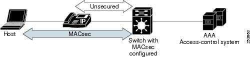
The same switch port hosts an unsecured phone session using CDP bypass. Since CDP bypass mode bypasses authentication to provide access based only on device type, the switch does not attempt to enter into an MKA exchange with the phone. If a voice VLAN is configured, CDP packets bypass MAC sec. For secure voice access, you should use MDA mode.
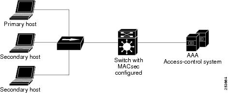
In standard (not 802.1x REV) 802. multiple-host mode, a port is open or closed based on a single authentication. If one user, the primary secured client services client host, is authenticated, the same level of network access is provided to any host connected to the same port. If a secondary host is a MACsec supplicant, it cannot be authenticated and traffic would no flow. A secondary host that is a non-MACsec host can send traffic to the network without authentication because it is in multiple-host mode. See .
Figure 2 Standard Multiple-Host Mode - Unsecured
MKA Statistics
Some MKA counters are aggregated globally, while others are updated both globally and per session. You can also obtain information about the status of MKA sessions.
Configuring an MKA Policy
Beginning in privileged EXEC mode, follow these steps to create an MKA Protocol policy:
Configuring MACsec on an Interface
Beginning in privileged EXEC mode, follow these steps to configure MACsec on an interface with one MACsec session for voice and one for data:
This is an example of configuring and verifying MACsec on an interface:
Catalyst 3560-C Updates to the Catalyst 3560 Switch Command Reference
- authentication event linksec fail action
- authentication linksec policy
- auto qos video
- clear macsec counters interface
- clear mka
- confidentiality-offset
- macsec
- media-type rj45
- mka default-policy
- media-type rj45
- mka policy (interface configuration)
- power inline police
- replay-protection window-size
- show controllers ethernet phy macsec
- show macsec
- show mka default-policy
- show mka policy
- show mka session
- show mka statistics
- show mka summary
- show power inline
- usb
- debug macsec
- debug mka
authentication event linksec fail action
To configure the required action for a link-security authentications failure, use the authentication event linksec fail action command in interface configuration mode. To disable the configured fail action, use the no form of this command.
authentication event linksec fail action {authorize vlan vlan-id | next-method}
Command Modes
Usage Guidelines
When link-security authentication fails because of unrecognized user credentials, this command specifies that the switch authorizes a restricted VLAN on the port.
You can verify your setting by entering the show authentication sessions privileged EXEC command.
authentication linksec policy
To set the static selection of a link-security policy, use the authentication linksec policy command in interface configuration mode. To return to the default state, use the no form of this command.
authentication linksec policy { must-not-secure | must-secure | should-secure }
Command Modes
Usage Guidelines
The linksec policy might change after a successful reauthentication started by a local timer or a change of authorization (CoA) reauthenticate command. If the policy changes from must-not-secure to must-secure after a reauthentication, the system attempts to secure the session. If the MACsec key does not renegotiate a MACsec connection after a reauthentication, the session is terminated, and all local states are removed.
A per-user policy received after authentication overrides the interface configuration policy.
You can verify your setting by entering the show authentication sessions privileged EXEC command.
auto qos video
Use the auto qos video interface configuration command on the to automatically configure quality of service (QoS) for video within a QoS domain. Use the no form of this command to return to the default setting.
auto qos video { cts | ip-camera }
Command Modes
Usage Guidelines
Use this command to configure the QoS appropriate for video traffic within the QoS domain. The QoS domain includes the switch, the network interior, and edge devices that can classify incoming traffic for QoS.
Auto-Qos configures the switch for video connectivity with a Cisco TelePresence system and a Cisco IP camera.
To take advantage of the auto-QoS defaults, you should enable auto-QoS before you configure other QoS commands. You can fine-tune the auto-QoS configuration after you enable auto-QoS.
Note![]() The switch applies the auto-QoS-generated commands as if the commands were entered from the command-line interface (CLI). An existing user configuration can cause the application of the generated commands to fail or to be overridden by the generated commands. These actions occur without warning. If all the generated commands are successfully applied, any user-entered configuration that was not overridden remains in the running configuration. Any user-entered configuration that was overridden can be retrieved by reloading the switch without saving the current configuration to memory. If the generated commands fail to be applied, the previous running configuration is restored.
The switch applies the auto-QoS-generated commands as if the commands were entered from the command-line interface (CLI). An existing user configuration can cause the application of the generated commands to fail or to be overridden by the generated commands. These actions occur without warning. If all the generated commands are successfully applied, any user-entered configuration that was not overridden remains in the running configuration. Any user-entered configuration that was overridden can be retrieved by reloading the switch without saving the current configuration to memory. If the generated commands fail to be applied, the previous running configuration is restored.
If this is the first port on which you have enabled auto-QoS, the auto-QoS-generated global configuration commands are executed followed by the interface configuration commands. If you enable auto-QoS on another port, only the auto-QoS-generated interface configuration commands for that port are executed.
When you enable the auto-QoS feature on the first port, these automatic actions occur:
- QoS is globally enabled ( mls qos global configuration command), and other global configuration commands are added.
After auto-QoS is enabled, do not modify a policy map or aggregate policer that includes AutoQoS in its name. If you need to modify the policy map or aggregate policer, make a copy of it, and change the copied policy map or policer. To use the new policy map instead of the generated one, remove the generated policy map from the interface, and apply the new policy map.
To display the QoS configuration that is automatically generated when auto-QoS is enabled, enable debugging before you enable auto-QoS. Use the debug auto qos privileged EXEC command to enable auto-QoS debugging. For more information, see the debug auto qos command.
To disable auto-QoS on a port, use the no auto qos video interface configuration command. Only the auto-QoS-generated interface configuration commands for this port are removed. If this is the last port on which auto-QoS is enabled and you enter the no auto qos video command, auto-QoS is considered disabled even though the auto-QoS-generated global configuration commands remain (to avoid disrupting traffic on other ports affected by the global configuration). You can use the no mls qos global configuration command to disable the auto-QoS-generated global configuration commands. With QoS disabled, there is no concept of trusted or untrusted ports because the packets are not modified (the CoS, DSCP, and IP precedence values in the packet are not changed). Traffic is switched in pass-through mode (packets are switched without any rewrites and classified as best effort without any policing).
You can verify the configuration by entering the show auto qos video interface interface-id privileged EXEC command.
Examples
This example shows how to enable auto-QoS for a Cisco Telepresence interface with conditional trust. The interface is trusted only if a Cisco Telepresence device is detected; otherwise, the port is untrusted.
clear macsec counters interface
To clear Media Access Control Security (MACsec) counters for an interface, use the clear macsec counters interface command in privileged EXEC mode.
clear mka
To clear MACsec Key Agreement (MKA) protocol sessions or information, use the clear mka command in privileged EXEC mode.
clear mka { all | sessions [ interface interface-id [ port-id port-id ]] | [ local-sci sci ] | statistics [ interface interface-id port-id port-id ] | [ local-sci sci ]}
Syntax Description
Command Modes
Usage Guidelines
When you enter the clear mka all command, the switch prompts for a confirmation and then deletes all active MKA sessions.
confidentiality-offset
To configure the confidentiality offset value for the MACsec Key Agreement (MKA) Protocol policy, use the confidentiality-offset command in MKA policy configuration mode. To return to the default setting, use the no or default form of this command
confidentiality-offset offset-value
Command Modes
Usage Guidelines
If no confidentiality offset is configured, no encryption offset is used.
To use this feature, both peers must support confidentiality offset.
You can verify the configuration by entering the show mka session detail privileged EXEC command.
macsec
To enable 802.1ae Media Access Control Security (MACsec) on an interface, use the macsec command in interface configuration mode. To disable MACsec on the interface, use the no form of this command.
Command Modes
Usage Guidelines
MACsec is supported only on downlink interfaces on the Catalyst 3560-C switch, Gigabit Ethernet 0/1 to 0/8.
The interface must be in switchport access mode to see this command.
Entering the macsec interface configuration command puts the interface in the MACsec mode.
You can verify the configuration by entering the show macsec summary privileged EXEC command.
media-type rj45
To manually select the RJ-45 console connection for input, whether or not there is a device connected to the USB console port, use the media-type rj45 command in line configuration mode. To return to the default setting, use the no form of this command. The USB console takes precedence if devices are connected to both consoles.
Command Modes
Usage Guidelines
The switch has a USB mini-Type B console connector and a USB console connector. Console output displays on devices connected to both connectors, but console input is active on only one input at a time, with the USB connector taking precedence. When you configure the media-type rj45 line configuration command, USB console operation is disabled and input always remains with the RJ-45 console.
Entering the no media-type rj45 line configuration command immediately activates the USB console when it is connected to a powered-on device with a terminal emulation application.
Removing the USB connector always enables input from the RJ-45 connector.
You can verify the configuration by entering the show running config privileged EXEC command.
mka default-policy
To apply the MACsec Key Agreement (MKA) protocol default policy on an interface, use the mka default-policy command in interface configuration mode. This command also enables MKA on the interface if no MKAs were applied. To disable MKA on the interface and clear any active MKA policies running on the interface, use the no form of this command.
Command Modes
Usage Guidelines
If another MKA policy is already applied to an interface, entering this command clears all active MKA sessions running on the interface.
If the MKA default policy has already been applied to the interface, you are notified, and no sessions are cleared.
To remove any MKA policy from the interface, including the default, enter the no mka policy interface configuration command.
You can verify the configuration by entering the show mka default-policy privileged EXEC command.
mka policy (global configuration)
To create or configure a MACsec Key Agreement (MKA) Protocol policy and to enter MKA policy configuration mode, use the mka policy command in global configuration mode. To delete the policy, use the no form of this command.
Command Modes
Usage Guidelines
If you enter the name of an existing policy, you see a warning that any changes to the policy deletes all active MKA sessions with that policy.
Whenever you change an MKA policy, active MKA sessions with that policy applied are cleared.
If you try to create a policy name with more than 16 characters, you see a warning message, and the policy is not created.
If you enter the no mka policy policy-name command to delete a policy that is applied to at least one interface, you are prompted to first remove the policy from all interfaces that it is applied to and then to reenter the command. If you attempt to delete a policy and the policy name does not exist, you are notified.
When you enter MKA policy mode, these commands are available:
- confidentiality-offset —Sets the confidentiality offset for MACsec operation
- default —Sets the policy to its defaults
- exit —Exits from MKA Policy configuration mode
- no —Deletes the MKA policy
- replay-protection —Configures MKA to use replay protection for MACsec operation
You can verify the configuration by entering the show mka policy privileged EXEC command.
mka policy (interface configuration)
To apply an existing MACsec Key Agreement (MKA) Protocol policy to an interface, use the mka policy command in interface configuration mode. This command also enables MKA on the interface if no MKAs have been applied. To remove an existing policy from the interface, disable MKA on the interface, and clear any active MKA sessions running on the interface, use the no form of this command.
Command Modes
Usage Guidelines
If a different MKA policy was applied to the interface, entering this command clears all active MKA sessions running on the interface.
If you enter a a policy name that is already applied to the interface, you are notified that the policy was already applied and no sessions are cleared.
If you enter a a policy name that does not exist, you are notified that the policy was not configured.
Entering the no mka policy interface command on an interface disables MKA on the interface and clears any active sessions that are running.
You can verify the configuration by entering the show mka policy privileged EXEC command.
power inline police
To enable policing of the real-time power consumption, use the power inline police in interface configuration mode. To disable this feature, use the no form of this command.
power inline police [ action { errdisable | log } ]
Syntax Description
Command Modes
Usage Guidelines
This command is supported only on Power over Ethernet (PoE)-capable ports. If you enter this command on a switch or port that does not support PoE, an error message appears.
The power inline police command is supported only on switches with PoE ports.
When policing of the real-time power consumption is enabled, the switch takes action when a powered device consumes more power than the allocated maximum amount.
When PoE is enabled, the switch senses the real-time power consumption of the powered device. This feature is called power monitoring or power sensing. The switch also polices the power usage with the power policing feature.
When power policing is enabled, the cutoff power on the PoE port is determined by one of these methods in this order:
1.![]() The user-defined power level that the switch budgets for the port when you enter the power inline consumption default wattage global configuration command or the power inline consumption wattage interface configuration command.
The user-defined power level that the switch budgets for the port when you enter the power inline consumption default wattage global configuration command or the power inline consumption wattage interface configuration command.
2.![]() The user-defined power level that limits the power allowed on the port when you enter the power inline auto max max-wattage or the power inline static max max-wattage interface configuration command
The user-defined power level that limits the power allowed on the port when you enter the power inline auto max max-wattage or the power inline static max max-wattage interface configuration command
3.![]() The power usage of the device set by the switch by using CDP power negotiation or the device IEEE classification.
The power usage of the device set by the switch by using CDP power negotiation or the device IEEE classification.
4.![]() The default power usage set by the switch; the default value is 15.4 W on a switch with PoE ports, and 30 W on a switch with PoE+ ports.
The default power usage set by the switch; the default value is 15.4 W on a switch with PoE ports, and 30 W on a switch with PoE+ ports.
Use the first or second method in the previous list to manually configure the cutoff-power value by entering the power inline consumption default wattage global configuration command, the power inline consumption wattage interface configuration command, or the power inline [ auto | static max ] max-wattage command. If you are do not manually configure the cutoff-power value, the switch automatically determines the value by using CDP power negotiation or the device IEEE classification, which is the third method in the list. If the switch cannot determine the value by using one of these methods, it uses the default value of 15.4 W or 30 W.
Note![]() For more information about the cutoff power value, the power consumption values that the switch uses, and the actual power consumption value of the connected device, see the “Power Monitoring and Power Policing” section in this document.
For more information about the cutoff power value, the power consumption values that the switch uses, and the actual power consumption value of the connected device, see the “Power Monitoring and Power Policing” section in this document.
If power policing is enabled, the switch polices power usage by comparing the real-time power consumption to the maximum power allocated on the PoE port. If the device uses more than the maximum power allocation (or cutoff power) on the port, the switch either turns power off to the port, or generates a syslog message and updates the LEDs (to blink amber) while still providing power to the device.
- To configure the switch to turn off power to the port and put the port in the error-disabled state, use the power inline police interface configuration command.
- To configure the switch to generate a syslog message while still providing power to the device, use the power inline police action log command.
If you do not enter the action log keywords, the default action is to shut down the port, turn off power, and put the port in the PoE error-disabled state. To configure the PoE port to automatically recover from the error-disabled state, use the errdisable detect cause inline-power global configuration command to enable error-disabled detection for the PoE cause and the errdisable recovery cause inline-power interval interval global configuration command to enable the recovery timer for the PoE error-disabled cause.

You can verify power inline configuration by entering the show power inline police privileged EXEC command.
Examples
This example shows how to enable policing of the power consumption and to configure the switch to generate a syslog message on the PoE port on a switch:
replay-protection window-size
To configure replay protection for Media Access Control Security (MACsec), use the replay-protection window-size command in MKA policy configuration mode. When replay protection is set, you must configure a window size in number of frames. Use the no form of the command to disable replay protection. Use the default form of this command to return to the default window size of 0 frames.
replay-protection window-size frames
Command Modes
Usage Guidelines
Entering the default replay-protection window-size command sets the number of frames to 0. Entering no default replay-protection window-size turns off replay protection.
Entering a window size of 0 is not the same as entering the no replay-protection command. Configuring a window size of 0 uses replay protection with a strict ordering of frames. Entering no replay-protection turns off replay-protection verification in MACsec.
You can verify your setting by entering the show mka session detail privileged EXEC command.
show controllers ethernet phy macsec
To display the internal Media Access Control Security (MACsec) counters or registers on an interface, use the show controllers ethernet phy macsec command in privileged EXEC mode.
show controllers ethernet interface-id phy macsec { counters | registers }
Command Modes
Usage Guidelines
The displayed information is useful for Cisco technical support representatives troubleshooting the switch.
show macsec
To display 802.1ae Media Access Control Security (MACsec) information, use the show macsec command in privileged EXEC mode.
Command Modes
Examples
This is sample output of the show macsec interface command when there is no MACsec session established on the interface:
This is sample output of the show macsec interface command after the session is established:
This is sample output of the show macsec summary command to see all established MACsec sessions:
show mka default-policy
To display information about the MACsec Key Agreement (MKA) Protocol default policy, use the show mka default-policy command in privileged EXEC mode.
show mka default-policy [ sessions ] [ detail ]
Syntax Description
Command Modes
Examples
This is sample output of the show mka default-policy command:
Switch# show mka default-policy
This is sample output of the show mka default-policy detail command:
Switch# show mka default-policy detail
This is sample output of the show mka default-policy sessions command:
Switch# show mka default-policy sessions
show mka policy
To display a summary of all defined MACsec Key Agreement (MKA) protocol policies, including the MKA default policy, or to display a summary of a specified policy, use the show mka policy command in privileged EXEC mode.
show mka policy [ policy-name [ sessions ] [ detail ]]
Syntax Description
Command Modes
Examples
This is sample output of the show mka policy command:
This is sample output of the show mka policy detail command:
Switch# show mka policy MkaPolicy detail
This is sample output of the show mka policy sessions command:
show mka session
To display a summary of active MACsec Key Agreement (MKA) Protocol sessions, use the show mka session command in privileged EXEC mode.
show mka session [ detail ] [ interface interface-id ] [ port-id port-id ]] [ local-sci sci ]
Syntax Description
Command Modes
Examples
This is sample output of the show mka session command:
This is sample output of the show mka session detail command:
This is sample output of the show mka session interface command:
show mka statistics
To display global MACsec Key Agreement (MKA) Protocol statistics and error counters from active and previous MKA sessions, use the show mka statistics command in privileged EXEC mode.
show mka statistics [ interface interface-id port-id port-id ] | [ local-sci sci ]}
Syntax Description
Command Modes
Examples
This is an example of the show mka statistics command output:
show mka summary
To display a summary of MACsec Key Agreement (MKA) sessions and global statistics, use the show mka summary command in privileged EXEC mode.
Command Modes
Examples
This is an example of the show mka summary command output:
show power inline
Use the show power inline user EXEC command to display the Power over Ethernet (PoE) status for the specified PoE port or for all PoE ports.
show power inline [ police [ interface-id ] | consumption | dynamic-priority ]
Syntax Description
Command Modes
Examples
This is an example of output from a Catalyst 3560CPD-8PT. It shows the available power and the power required by each connected device.
Table 15 describes the output fields.
The Catalyst 3560CG-8TC switch downlink ports cannot provide power to end devices. This is an example of output from the show power inline command on a Catalyst 3560CG-8PT switch:
This is an example of the outout of the show power inline police privileged EXEC command on a Catalyst 3560CPD-8PT:
Table 16 describes the output fields.
This is an example of output from the show power inline police interface-id command on a switch.
This is an example of output from the show power inline consumption command on all PoE switch ports:
This is an example of output from the show power inline dynamic-priority command on a switch.
usb
To configure an inactivity timeout on the USB console, use the usb command in console line configuration mode. To remove the inactivity timeout use the no form of this command.
Command Modes
Usage Guidelines
The switch has a configurable timeout inactivity that activates the RJ-45 console if the USB console has been activated but no input activity has occurred on the USB console for a specified time period. When the USB console is deactivated due to an inactivity timeout, you can restore its operation by disconnecting and reconnecting the USB cable.
debug macsec
To enable debugging of 802.1ae Media Access Control Security (MACsec), use the debug macsec command in privileged EXEC mode. To disable debugging, use the no form of this command.
debug macsec [ error | events ]
Command Modes
Usage Guidelines
Entering the debug macsec command with no keywords starts all MACsec debugging facilities.
The undebug macsec command is the same as the no debug macsec command.
When you enable debugging, it is enabled only on the stack master. To enable debugging on a stack member, you can start a session from the stack master by using the session switch-number privileged EXEC command. Then enter the debug command at the command-line prompt of the stack member. You can use the remote command stack-member-number LINE privileged EXEC command on the stack master switch to enable debugging on a member switch without starting a session.
debug mka
To enable debugging of the MACsec Key Agreement (MKA) protocol sessions, use the debug mka command in privileged EXEC mode. To disable debugging, use the no form of this command.
debug mka [ errors | events | lli | mli | packets | trace ]
no debug mka [ errors | events | lli | mli | packets | trace ]
Syntax Description
Command Modes
Usage Guidelines
Entering the debug mka command with no keywords enables all MKA debugging facilities.
The undebug backup command is the same as the no debug backup command.
When you enable debugging, it is enabled only on the stack master. To enable debugging on a stack member, you can start a session from the stack master by using the session switch-number privileged EXEC command. Then enter the debug command at the command-line prompt of the stack member. You also can use the remote command stack-member-number LINE privileged EXEC command on the stack master switch to enable debugging on a member switch without starting a session.
Related Documentation
These documents with information about the Catalyst 3560-C switches are available on Cisco.com:
http://www.cisco.com/en/US/products/ps11289/tsd_products_support_series_home.html
- Catalyst 3560-C and 2960-C Switch Hardware Installation Guide
- Catalyst 3560-C and 2960-C Switch Getting Started Guide
- Regulatory Compliance and Safety Information for the Catalyst 3560-C and 2960-C Switch
These documents with information about the Catalyst 3560 switches are available at Cisco.com:
http://www.cisco.com/en/US/products/hw/switches/ps5528/tsd_products_support_series_home.html
- Catalyst 3560 Switch Software Configuration Guide
- Catalyst 3560 Switch Command Reference
- Catalyst 3750, 3560, 3550, 2975, 2970, 2960, and 2960-S Switch System Message Guide
For other information about related products, see these documents:
- Device manager online help (available on the switch)
- Smart Install Configuration Guide
- Auto Smartports Configuration Guide
- Cisco EnergyWise Configuration Guide
- For more information about the Network Admission Control (NAC) features, see the Network Admission Control Software Configuration Guide
- Information about Cisco SFP, SFP+, and GBIC modules is available from this Cisco.com site:
http://www.cisco.com/en/US/products/hw/modules/ps5455/prod_installation_guides_list.html
SFP compatibility matrix documents are available from this Cisco.com site:
http://www.cisco.com/en/US/products/hw/modules/ps5455/products_device_support_tables_list
.html
Obtaining Documentation and Submitting a Service Request
For information on obtaining documentation, submitting a service request, and gathering additional information, see the monthly What’s New in Cisco Product Documentation, which also lists all new and revised Cisco technical documentation:
http://www.cisco.com/en/US/docs/general/whatsnew/whatsnew.html
Subscribe to the What’s New in Cisco Product Documentation as a Really Simple Syndication (RSS) feed and set content to be delivered directly to your desktop using a reader application. The RSS feeds are a free service and Cisco currently supports RSS version 2.0.
This document is to be used in conjunction with the documents listed in the “Related Documentation” section.
Cisco and the Cisco logo are trademarks or registered trademarks of Cisco and/or its affiliates in the U.S. and other countries. To view a list of Cisco trademarks, go to this URL: www.cisco.com/go/trademarks. Third-party trademarks mentioned are the property of their respective owners. The use of the word partner does not imply a partnership relationship between Cisco and any other company. (1110R)
Any Internet Protocol (IP) addresses used in this document are not intended to be actual addresses. Any examples, command display output, and figures included in the document are shown for illustrative purposes only. Any use of actual IP addresses in illustrative content is unintentional and coincidental.
 Feedback
Contact Cisco
- Open a Support Case

- (Requires a Cisco Service Contract)