Catalyst 2960-S Switch Hardware Installation Guide
Bias-Free Language
The documentation set for this product strives to use bias-free language. For the purposes of this documentation set, bias-free is defined as language that does not imply discrimination based on age, disability, gender, racial identity, ethnic identity, sexual orientation, socioeconomic status, and intersectionality. Exceptions may be present in the documentation due to language that is hardcoded in the user interfaces of the product software, language used based on RFP documentation, or language that is used by a referenced third-party product. Learn more about how Cisco is using Inclusive Language.
- Updated:
- May 15, 2009
Chapter: Troubleshooting
Diagnosing Problems
The LEDs on the front panel provide troubleshooting information about the switch. They show POST failures, port-connectivity problems, and overall switch performance. You can also get statistics from the device manager, from the CLI, or from an SNMP workstation. See the software configuration guide, the switch command reference guide on Cisco.com, or the documentation that came with your SNMP application for details.
Switch POST Results
See the “Verifying Switch Operation” section for information on POST.

Note![]() POST failures are usually fatal. Contact your Cisco technical support representative if your switch does not pass POST.
POST failures are usually fatal. Contact your Cisco technical support representative if your switch does not pass POST.
Switch LEDs
If you have physical access to the switch, look at the port LEDs for troubleshooting information about the switch. See the “LEDs” section for a description of the LED colors and their meanings.
Switch Connections
Bad or Damaged Cable
Always examine the cable for marginal damage or failure. A cable might be just good enough to connect at the physical layer, but it could corrupt packets as a result of subtle damage to the wiring or connectors. You can identify this situation because the port has many packet errors or the port constantly flaps (loses and regains link).
- Examine or exchange the copper or fiber-optic cable with a known, good cable.
- Look for broken or missing pins on cable connectors.
- Rule out any bad patch panel connections or media convertors between the source and the destination. If possible, bypass the patch panel, or eliminate faulty media convertors (fiber-optic-to-copper).
- Try the cable in another port or interface, if possible, to see if the problem follows the cable.
- Remove and inspect the stack cable and stack port for bent pins or damaged connectors. If the cable is bad, replace it with a known good cable.
Ethernet and Fiber-Optic Cables
Make sure that you have the correct cable for the connection
- For Ethernet, use Category 3 copper cable for 10 Mb/s UTP connections. Use either Category 5, Category 5e, or Category 6 UTP for 10/100 or 10/100/1000 Mb/s connections.
- For fiber-optic cables, verify that you have the correct cable for the distance and port type. Make sure that the connected device ports both match and use the same type encoding, optical frequency, and fiber type.
- For copper connections, determine if a crossover cable was used when a straight-through was required or the reverse. Enable auto-MDIX on the switch, or replace the cable. See Table 1-1 for recommended Ethernet cables.
Link Status
Verify that both sides have link. A single broken wire or a shutdown port can cause one side to show link even though the other side does not have link.
A port LED that is on does not guarantee that the cable is fully functional. The cable might have encountered physical stress that causes it to function at a marginal level. If the port LED does not turn on:
- Connect the cable from the switch to a known good device.
- Make sure that both ends of the cable are connected to the correct ports.
- Verify that both devices have power.
- Verify that you are using the correct cable type. See Appendix 1, “Connector and Cable Specifications” for information.
- Look for loose connections. Sometimes a cable appears to be seated, but is not. Disconnect the cable and then reconnect it.
10/100 or 10/100/1000 Port Connections
10/100 or 10/100/1000 PoE Port Connections
A powered device connected to PoE port does not receive power:
- Use the Mode button to show the PoE status for all ports. See Table 1-8 and Table 1-9 for descriptions of the LEDs and their meanings.
- Use the show interfaces privileged EXEC command to see if the port is in error-disabled, disabled, or shutdown. Re-enable the port if necessary.
- Verify that the power supply installed in the switch meets the power requirements of your connected devices. See the “10/100 PoE+ Ports” section and the “10/100/1000 PoE+ Ports” section.
- Verify the cable type. Many legacy powered devices, including older Cisco IP phones and access points that do not fully support IEEE 802.3af, might not support PoE when connected to the switch by a crossover cable. Replace the crossover cable with a straight-through cable.

SFP and SFP+ Module
Use only Cisco SFP or SFP+ modules in the switch. Each Cisco module has an internal serial EEPROM that is encoded with security information. This encoding provides a way for Cisco to identify and validate that the module meets the requirements for the switch.
- Inspect the SFP module. Exchange the suspect module with a known good module. Verify that the module is supported on this platform. (The switch release notes on Cisco.com list the SFP modules that the switch supports.)
- Use the show interfaces privileged EXEC command to see if the port or module is error-disabled, disabled, or shutdown. Re-enable the port if needed.
- Make sure that all fiber-optic connections are properly cleaned and securely connected.
Interface Settings
Verify that the interface is not disabled or powered off. If an interface is manually shut down on either side of the link, it does not come up until you re-enable the interface. Use the show interfaces privileged EXEC command to see if the interface is error-disabled, disabled, or shutdown on either side of the connection. If needed, re-enable the interface.
Ping End Device
Ping from the directly connected switch first, and then work your way back port by port, interface by interface, trunk by trunk, until you find the source of the connectivity issue. Make sure that each switch can identify the end device MAC address in its Content-Addressable Memory (CAM) table.
Spanning Tree Loops
STP loops can cause serious performance issues that look like port or interface problems.
A unidirectional link can cause loops. It occurs when the traffic sent by the switch is received by its neighbor, but the traffic from the neighbor is not received by the switch. A broken fiber-optic cable, other cabling problems, or a port issue could cause this one-way communication.
You can enable UniDirectional Link Detection (UDLD) on the switch to help identify unidirectional link problems. For information about enabling UDLD on the switch, see the “Understanding UDLD” section in the switch software configuration guide on Cisco.com.
Switch Performance
Speed, Duplex, and Autonegotiation
If the port statistics show a large amount of alignment errors, frame check sequence (FCS), or late-collisions errors, this might mean a speed or duplex mismatch.
A common issue with speed and duplex occurs when duplex and speed settings are mismatched between two switches, between a switch and a router, or between the switch and a workstation or server. Mismatches can happen when manually setting the speed and duplex or from autonegotiation issues between the two devices.
To maximize switch performance and to ensure a link, follow one of these guidelines when changing the duplex or the speed settings.
- Let both ports autonegotiate both speed and duplex.
- Manually set the speed and duplex parameters for the interfaces on both ends of the connection.
- If a remote device does not autonegotiate, use the same duplex settings on the two ports. The speed parameter adjusts itself even if the connected port does not autonegotiate.
Autonegotiation and Network Interface Cards
Problems sometimes occur between the switch and third-party network interface cards (NICs). By default, the switch ports and interfaces autonegotiate. Laptops or other devices are commonly set to autonegotiate, yet sometimes autonegotiation issues occur.
To troubleshoot autonegotiation problems, try manually setting both sides of the connection. If this does not solve the problem, there could be a problem with the firmware or software on your NIC. You can resolve this by upgrading the NIC driver to the latest version.
Cabling Distance
If the port statistics show excessive FCS, late-collision, or alignment errors, verify that the cable distance from the switch to the connected device meets the recommended guidelines. See the “Cables and Adapters” section.
Clearing the Switch IP Address and Configuration
If you have configured a new switch with a wrong IP address, or if all of the switch LEDs start blinking when you are trying to enter Express Setup mode, you can clear the configured IP address. The switch returns to the factory default settings.
Note![]() This procedure clears the IP address and all configuration information stored on the switch. Do not follow this procedure unless you want to completely reconfigure the switch.
This procedure clears the IP address and all configuration information stored on the switch. Do not follow this procedure unless you want to completely reconfigure the switch.
1.![]() Press and hold the Mode button (Figure 1-1).
Press and hold the Mode button (Figure 1-1).
2.![]() The switch LEDs blink after about 2 seconds. If the switch is not configured, the LEDs above the Mode button turn green. You can omit the next step.
The switch LEDs blink after about 2 seconds. If the switch is not configured, the LEDs above the Mode button turn green. You can omit the next step.
3.![]() Continue holding down the Mode button. The LEDs stop blinking after 8 seconds, and then the switch reboots.
Continue holding down the Mode button. The LEDs stop blinking after 8 seconds, and then the switch reboots.
You can now configure the switch by using Express Setup as described in the switch getting started guide.
You can also configure the switch by using the CLI setup procedure described in the “Configuring the Switch with the CLI-Based Setup Program” appendix.
Finding the Switch Serial Number
If you contact Cisco Technical Assistance, you need to know the switch serial number. Figure 1-1 and Figure 1-2 show the serial number locations. Figure 1-6 shows the FlexStack module serial number location. You can also use the show version privileged EXEC command to see the switch serial number.
Figure 1-1 Serial Number Location for the Catalyst 2960S-48FPD-L, 2960S-48LPD-L, 2960S-24PD-L,2960S-48FPS-L, 2960S-48LPS-L, and 2960S-24PS-L Switches
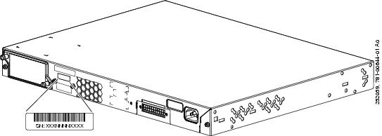
Figure 1-2 Serial Number Location for the Catalyst 2960S-48TD-L, 2960S-24TD-L, 2960S-48TS-L, 2960S-24TS-L, 2960S-48TS-S, and 2960S-24TS-S Switches
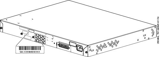
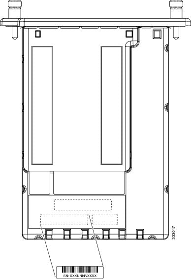
Figure 1-3 Serial Number Location for the Catalyst 2960S-F48FPS-L, 2960S-F48LPS-L, and 2960S-F24PS-L Switches
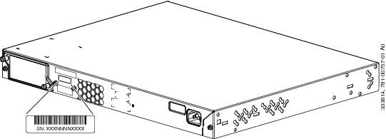
Figure 1-4 Serial Number Location for the Catalyst 2960S-F48TS-L and 2960S-F24TS-L Switches
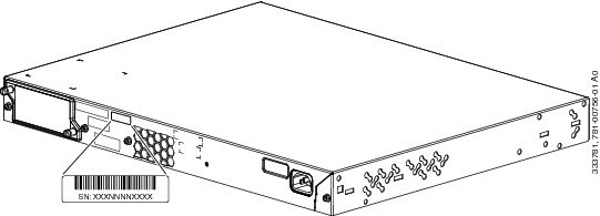
Figure 1-5 Serial Number Location for the Catalyst 2960S-F48TS-S, and 2960S-F24TS-S Switches
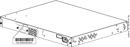
Figure 1-6 Serial Number Location for the C2960S-STACK Module
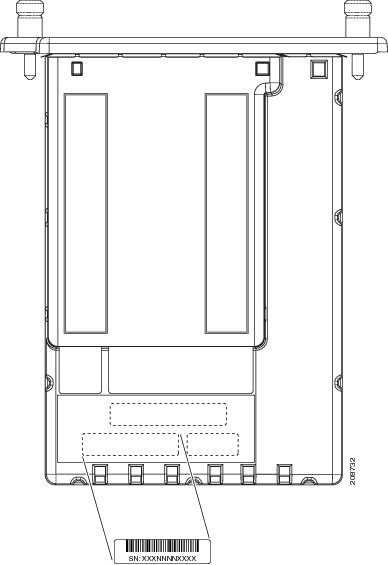
Figure 1-7 Serial Number Location for the C2960S-F-STACK Module
Replacing a Failed Stack Member
1.![]() Get a replacement switch that has the same model number as the failed switch.
Get a replacement switch that has the same model number as the failed switch.
2.![]() Power down the failed switch.
Power down the failed switch.
3.![]() Make sure that the replacement switch is off and that the FlexStack module is installed.
Make sure that the replacement switch is off and that the FlexStack module is installed.
4.![]() Connect the switch to the stack.
Connect the switch to the stack.
5.![]() Make the same connections on the replacement switch that were on the failed switch.
Make the same connections on the replacement switch that were on the failed switch.
6.![]() Reinstall any modules, and make cable connections.
Reinstall any modules, and make cable connections.
7.![]() Power on the replacement switch.
Power on the replacement switch.
The replacement switch has the same configuration for all the interfaces as the failed switch and functions the same as the failed switch.
If you had manually set the member numbers for any stack members, you need to manually assign the replacement switch with the same member number as the failed switch. See the switch software configuration guide on Cisco.com.
Diagnosing Problems
The LEDs on the front panel provide troubleshooting information about the switch. They show POST failures, port-connectivity problems, and overall switch performance. You can also get statistics from the device manager, from the CLI, or from an SNMP workstation. See the software configuration guide, the switch command reference guide on Cisco.com, or the documentation that came with your SNMP application for details.
Switch POST Results
See the “Verifying Switch Operation” section for information on POST.
Note
POST failures are usually fatal. Contact your Cisco technical support representative if your switch does not pass POST.
Switch LEDs
If you have physical access to the switch, look at the port LEDs for troubleshooting information about the switch. See the “LEDs” section for a description of the LED colors and their meanings.
Bad or Damaged Cable
Always examine the cable for marginal damage or failure. A cable might be just good enough to connect at the physical layer, but it could corrupt packets as a result of subtle damage to the wiring or connectors. You can identify this situation because the port has many packet errors or the port constantly flaps (loses and regains link).
- Examine or exchange the copper or fiber-optic cable with a known, good cable.
- Look for broken or missing pins on cable connectors.
- Rule out any bad patch panel connections or media convertors between the source and the destination. If possible, bypass the patch panel, or eliminate faulty media convertors (fiber-optic-to-copper).
- Try the cable in another port or interface, if possible, to see if the problem follows the cable.
- Remove and inspect the stack cable and stack port for bent pins or damaged connectors. If the cable is bad, replace it with a known good cable.
Ethernet and Fiber-Optic Cables
Make sure that you have the correct cable for the connection
- For Ethernet, use Category 3 copper cable for 10 Mb/s UTP connections. Use either Category 5, Category 5e, or Category 6 UTP for 10/100 or 10/100/1000 Mb/s connections.
- For fiber-optic cables, verify that you have the correct cable for the distance and port type. Make sure that the connected device ports both match and use the same type encoding, optical frequency, and fiber type.
- For copper connections, determine if a crossover cable was used when a straight-through was required or the reverse. Enable auto-MDIX on the switch, or replace the cable. See Table 1-1 for recommended Ethernet cables.
Link Status
Verify that both sides have link. A single broken wire or a shutdown port can cause one side to show link even though the other side does not have link.
A port LED that is on does not guarantee that the cable is fully functional. The cable might have encountered physical stress that causes it to function at a marginal level. If the port LED does not turn on:
- Connect the cable from the switch to a known good device.
- Make sure that both ends of the cable are connected to the correct ports.
- Verify that both devices have power.
- Verify that you are using the correct cable type. See Appendix 1, “Connector and Cable Specifications” for information.
- Look for loose connections. Sometimes a cable appears to be seated, but is not. Disconnect the cable and then reconnect it.
10/100 or 10/100/1000 PoE Port Connections
A powered device connected to PoE port does not receive power:
- Use the Mode button to show the PoE status for all ports. See Table 1-8 and Table 1-9 for descriptions of the LEDs and their meanings.
- Use the show interfaces privileged EXEC command to see if the port is in error-disabled, disabled, or shutdown. Re-enable the port if necessary.
- Verify that the power supply installed in the switch meets the power requirements of your connected devices. See the “10/100 PoE+ Ports” section and the “10/100/1000 PoE+ Ports” section.
- Verify the cable type. Many legacy powered devices, including older Cisco IP phones and access points that do not fully support IEEE 802.3af, might not support PoE when connected to the switch by a crossover cable. Replace the crossover cable with a straight-through cable.
SFP and SFP+ Module
Use only Cisco SFP or SFP+ modules in the switch. Each Cisco module has an internal serial EEPROM that is encoded with security information. This encoding provides a way for Cisco to identify and validate that the module meets the requirements for the switch.
- Inspect the SFP module. Exchange the suspect module with a known good module. Verify that the module is supported on this platform. (The switch release notes on Cisco.com list the SFP modules that the switch supports.)
- Use the show interfaces privileged EXEC command to see if the port or module is error-disabled, disabled, or shutdown. Re-enable the port if needed.
- Make sure that all fiber-optic connections are properly cleaned and securely connected.
Interface Settings
Verify that the interface is not disabled or powered off. If an interface is manually shut down on either side of the link, it does not come up until you re-enable the interface. Use the show interfaces privileged EXEC command to see if the interface is error-disabled, disabled, or shutdown on either side of the connection. If needed, re-enable the interface.
Ping End Device
Ping from the directly connected switch first, and then work your way back port by port, interface by interface, trunk by trunk, until you find the source of the connectivity issue. Make sure that each switch can identify the end device MAC address in its Content-Addressable Memory (CAM) table.
Spanning Tree Loops
STP loops can cause serious performance issues that look like port or interface problems.
A unidirectional link can cause loops. It occurs when the traffic sent by the switch is received by its neighbor, but the traffic from the neighbor is not received by the switch. A broken fiber-optic cable, other cabling problems, or a port issue could cause this one-way communication.
You can enable UniDirectional Link Detection (UDLD) on the switch to help identify unidirectional link problems. For information about enabling UDLD on the switch, see the “Understanding UDLD” section in the switch software configuration guide on Cisco.com.
Speed, Duplex, and Autonegotiation
If the port statistics show a large amount of alignment errors, frame check sequence (FCS), or late-collisions errors, this might mean a speed or duplex mismatch.
A common issue with speed and duplex occurs when duplex and speed settings are mismatched between two switches, between a switch and a router, or between the switch and a workstation or server. Mismatches can happen when manually setting the speed and duplex or from autonegotiation issues between the two devices.
To maximize switch performance and to ensure a link, follow one of these guidelines when changing the duplex or the speed settings.
- Let both ports autonegotiate both speed and duplex.
- Manually set the speed and duplex parameters for the interfaces on both ends of the connection.
- If a remote device does not autonegotiate, use the same duplex settings on the two ports. The speed parameter adjusts itself even if the connected port does not autonegotiate.
Autonegotiation and Network Interface Cards
Problems sometimes occur between the switch and third-party network interface cards (NICs). By default, the switch ports and interfaces autonegotiate. Laptops or other devices are commonly set to autonegotiate, yet sometimes autonegotiation issues occur.
To troubleshoot autonegotiation problems, try manually setting both sides of the connection. If this does not solve the problem, there could be a problem with the firmware or software on your NIC. You can resolve this by upgrading the NIC driver to the latest version.
Cabling Distance
If the port statistics show excessive FCS, late-collision, or alignment errors, verify that the cable distance from the switch to the connected device meets the recommended guidelines. See the “Cables and Adapters” section.
Clearing the Switch IP Address and Configuration
If you have configured a new switch with a wrong IP address, or if all of the switch LEDs start blinking when you are trying to enter Express Setup mode, you can clear the configured IP address. The switch returns to the factory default settings.
Note
1.
2.
3.
You can now configure the switch by using Express Setup as described in the switch getting started guide.
You can also configure the switch by using the CLI setup procedure described in the “Configuring the Switch with the CLI-Based Setup Program” appendix.
Finding the Switch Serial Number
If you contact Cisco Technical Assistance, you need to know the switch serial number. Figure 1-1 and Figure 1-2 show the serial number locations. Figure 1-6 shows the FlexStack module serial number location. You can also use the show version privileged EXEC command to see the switch serial number.
Figure 1-1 Serial Number Location for the Catalyst 2960S-48FPD-L, 2960S-48LPD-L, 2960S-24PD-L,2960S-48FPS-L, 2960S-48LPS-L, and 2960S-24PS-L Switches
Figure 1-2 Serial Number Location for the Catalyst 2960S-48TD-L, 2960S-24TD-L, 2960S-48TS-L, 2960S-24TS-L, 2960S-48TS-S, and 2960S-24TS-S Switches
Figure 1-3 Serial Number Location for the Catalyst 2960S-F48FPS-L, 2960S-F48LPS-L, and 2960S-F24PS-L Switches
Figure 1-4 Serial Number Location for the Catalyst 2960S-F48TS-L and 2960S-F24TS-L Switches
Figure 1-5 Serial Number Location for the Catalyst 2960S-F48TS-S, and 2960S-F24TS-S Switches
Figure 1-6 Serial Number Location for the C2960S-STACK Module
Figure 1-7 Serial Number Location for the C2960S-F-STACK Module
Replacing a Failed Stack Member
1.
2.
3.
4.
5.
6.
7.
The replacement switch has the same configuration for all the interfaces as the failed switch and functions the same as the failed switch.
If you had manually set the member numbers for any stack members, you need to manually assign the replacement switch with the same member number as the failed switch. See the switch software configuration guide on Cisco.com.
 Feedback