System Management Configuration Guide, Cisco DCNM for SAN, Release 7.x
Bias-Free Language
The documentation set for this product strives to use bias-free language. For the purposes of this documentation set, bias-free is defined as language that does not imply discrimination based on age, disability, gender, racial identity, ethnic identity, sexual orientation, socioeconomic status, and intersectionality. Exceptions may be present in the documentation due to language that is hardcoded in the user interfaces of the product software, language used based on RFP documentation, or language that is used by a referenced third-party product. Learn more about how Cisco is using Inclusive Language.
- Updated:
- May 7, 2015
Chapter: Managing Virtual Switches
- Information About Virtual Switches
- Licensing Requirements for Virtual Switches
- Prerequisites
- Platform Support
- Configuring Domains
- Configuring Server Connections
- Displaying Neighbor Devices
- Configuring a Control Interface
- Monitoring Virtual Switches
- Field Descriptions
- Additional References
- Feature History for Virtual Switches
Managing Virtual Switches
The Cisco Nexus 1000V is a virtual access software switch that works with VMware vSphere 4.0 and has the following components:
- Virtual Supervisor Module (VSM)—Control plane of the switch and a virtual machine that runs Cisco NX-OS.
- Virtual Ethernet Module (VEM) —Virtual line card embedded in each VMware vSphere (ESX) host.
Managing a virtual switch involves configuring its domain and server connections.
A domain is an instance of a Cisco Nexus 1000V Series switch device, including dual redundant VSMs and managed VEMs, within a VMware vCenter server. Each domain is distinguished by a unique integer called the domain identifier.
In order for the Cisco Nexus 1000V to connect to a vCenter Server or an ESX server, you must first define the connection parameters. All communication with the vCenter Server is secured by the Transport Layer Security (TLS) protocol.
This chapter describes how to manage virtual switches using Cisco Data Center Network Manager (DCNM).
This chapter includes the following sections:
- Information About Virtual Switches
- Licensing Requirements for Virtual Switches
- Prerequisites
- Platform Support
- Configuring Domains
- Configuring Server Connections
- Displaying Neighbor Devices
- Configuring a Control Interface
- Monitoring Virtual Switches
- Field Descriptions
- Additional References
- Feature History for Virtual Switches
Information About Virtual Switches
The Cisco Nexus 1000V is a virtual access software switch that works with VMware vSphere 4.0 and has the following components:
- Virtual Supervisor Module (VSM)—Control plane of the switch and a virtual machine that runs Cisco NX-OS.
- Virtual Ethernet Module (VEM)—Virtual line card that is embedded in each VMware vSphere (ESX) host.
Managing a virtual switch involves configuring its domain and server connection.
This section includes the following topics:
Domains
A domain is an instance of a Cisco Nexus 1000V device, including dual redundant Virtual Supervisor Modules (VSMs) and managed Virtual Ethernet Modules (VEMs), within a VMware vCenter Server. Each domain needs to be distinguished by a unique integer called the domain identifier.
You can configure Layer 2 or Layer 3 transport control mode for communication between the VSM and VEMs.
Layer 2 Control
Layer 2 is a transport control mode used for communication between the VSM and VEMs. However, you can create and specify the VLAN to be used.
Layer 3 Control
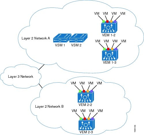
Layer 3 control, or IP connectivity, is supported between the VSM and VEM for control and packet traffic. With Layer 3 control, a VSM can be Layer 3 accessible and control hosts can reside in a separate Layer 2 network. All hosts controlled by a VSM, however, must still reside in the same Layer 2 network. Because a VSM cannot control a host that is outside of the Layer 2 network it controls, the host on which it resides must be controlled by another VSM.
Figure 4-1 shows an example of Layer 3 control where VSM0 controls VEM_0_1. VEM_0_1, in turn, hosts VSM1 and VSM2, and VSM1 and VSM2 control VEMs in other Layer 2 networks.
Figure 4-1 Example of Layer 3 Control IP Connectivity
Server Connections
The Nexus 1000V device requires a connection to a VMware vCenter server for management of its distributed virtual switch (DVS) and host mapping to the Virtual Ethernet Modules (VEMs).
Licensing Requirements for Virtual Switches
The following table shows the licensing requirements for this feature:
Prerequisites
The following prerequisite is required for using the Virtual Switches feature on Cisco DCNM. For a full list of feature-specific prerequisites, see the platform-specific documentation.
- System-message logging levels for the Virtual Switches feature must meet or exceed Cisco DCNM requirements. During device discovery, Cisco DCNM detects inadequate logging levels and raises them to the minimum requirements. Cisco Nexus 7000 Series Switches that run Cisco NX-OS Release 4.0 are an exception. For Cisco NX-OS Release 4.0, prior to device discovery, use the command-line interface to configure logging levels to meet or exceed Cisco DCNM requirements. For more information, see the Cisco DCNM Fundamentals Guide, Release 5.x.
Platform Support
The following platform supports this feature. For platform-specific information, including guidelines and limitations, system defaults, and configuration limits, see the corresponding documentation.
|
|
|
|---|---|
Configuring Domains
You can configure domains in Cisco DCNM.
This section includes the following topics:
- Creating a Domain with Layer 2 Control
- Creating a Domain with Layer 3 Control
- Changing a Domain to Layer 3 Control
- Changing a Domain to Layer 2 Control
- Configuring a Domain with a Control VLAN
- Configuring a Domain with a Packet VLAN
Creating a Domain with Layer 2 Control
You can create a domain name for the Cisco Nexus 1000V Series switch that identifies the Virtual Supervisor Module (VSM) and Virtual Ethernet Modules (VEMs) and then add control and packet VLANs for communication and management. This process is part of the initial installation process. If you need to create a domain after the initial setup, you can do so by using this procedure.
BEFORE YOU BEGIN
Be aware that if two or more VSMs share the same control and/or packet VLAN, the domain helps identify the VEMs that are managed by each VSM.
You must have a unique domain ID for this instance.
We recommend that you use one VLAN for control traffic and a different VLAN for packet traffic.
We recommend that you use a distinct VLAN for each domain.
For information about changing a domain ID after adding a second VSM, see the documentation for your platform.
DETAILED STEPS
Step 1![]() From the Feature Selector pane, choose Inventory > Virtual Switch.
From the Feature Selector pane, choose Inventory > Virtual Switch.
Summary information for each managed virtual switch appears in the Summary pane.
Step 2![]() From the Summary pane, choose the device for which you want to create a domain.
From the Summary pane, choose the device for which you want to create a domain.
Step 3![]() From the Details pane, choose the Details tab.
From the Details pane, choose the Details tab.
Step 4![]() Expand the Domain Settings section.
Expand the Domain Settings section.
Step 5![]() (Optional) From the menu bar, choose Actions > Reset Domain Setting(s).
(Optional) From the menu bar, choose Actions > Reset Domain Setting(s).
Step 6![]() In the Domain ID field, enter an ID number for the domain.
In the Domain ID field, enter an ID number for the domain.
Step 7![]() In the Control mode drop-down list, choose L2.
In the Control mode drop-down list, choose L2.
Layer 2 control uses VLAN 1 for the control and packet VLANs by default. If desired, you can configure specific control and packet VLANs for the domain. See the “Configuring a Domain with a Control VLAN” section and the “Configuring a Domain with a Packet VLAN” section.
Step 8![]() From the menu bar, choose File > Deploy to apply your changes to the device.
From the menu bar, choose File > Deploy to apply your changes to the device.
RELATED TOPICS
Creating a Domain with Layer 3 Control
You can create a domain name that identifies the Virtual Supervisor Module (VSM) and Virtual Ethernet Modules (VEMs) for the Cisco Nexus 1000V Series switch. This process is part of the initial setup when installing the software. If you need to create a domain after initial setup, you can do so using this procedure.
BEFORE YOU BEGIN
Configure the interface that you plan to use (mgmt 0 or control 0) with an IP address. For more information, see the “Configuring a Control Interface” section.
Configure a port profile for Layer 3 control. See the Interfaces Configuration Guide, Cisco DCNM for LAN, Release 5.x.
Create a VMware kernel NIC interface on each host and apply the Layer 3 control port profile to it. For more information, see your VMware documentation.
Ensure that you have a unique domain ID for this instance.
For information about changing a domain ID after adding a second VSM, see the documentation for your platform.
DETAILED STEPS
Step 1![]() From the Feature Selector pane, choose Inventory > Virtual Switch.
From the Feature Selector pane, choose Inventory > Virtual Switch.
Summary information for each managed virtual switch appears in the Summary pane.
Step 2![]() From the Summary pane, choose the device for which you want to create a domain.
From the Summary pane, choose the device for which you want to create a domain.
Step 3![]() From the Details pane, choose the Details tab.
From the Details pane, choose the Details tab.
Step 4![]() Expand the Domain Settings section.
Expand the Domain Settings section.
Step 5![]() (Optional) From the menu bar, choose Actions > Reset Domain Setting(s).
(Optional) From the menu bar, choose Actions > Reset Domain Setting(s).
Step 6![]() In the Domain ID field, enter an ID number for the domain.
In the Domain ID field, enter an ID number for the domain.
Step 7![]() In the Control Interface drop-down list, choose either mgmt0 or control0 as the interface to use.
In the Control Interface drop-down list, choose either mgmt0 or control0 as the interface to use.
Step 8![]() From the menu bar, choose File > Deploy to apply your changes to the device.
From the menu bar, choose File > Deploy to apply your changes to the device.
RELATED TOPICS
Changing a Domain to Layer 3 Control
You can change the control mode from Layer 2 to Layer 3 for the Virtual Supervisor Module (VSM) domain control and packet traffic.
BEFORE YOU BEGIN
Configure the interface that you plan to use (mgmt 0 or control 0) with an IP address. For more information, see the “Configuring a Control Interface” section.

Note![]() You must perform the steps in this procedure in order. The control and packet VLANs must be disabled before the Layer 3 control can be enabled.
You must perform the steps in this procedure in order. The control and packet VLANs must be disabled before the Layer 3 control can be enabled.
DETAILED STEPS
Step 1![]() From the Feature Selector pane, choose Inventory > Virtual Switch.
From the Feature Selector pane, choose Inventory > Virtual Switch.
Summary information for each managed virtual switch appears in the Summary pane.
Step 2![]() From the Summary pane, choose the device for which you want to create a domain.
From the Summary pane, choose the device for which you want to create a domain.
Step 3![]() From the Details pane, choose the Details tab.
From the Details pane, choose the Details tab.
Step 4![]() Expand the Domain Settings section.
Expand the Domain Settings section.
Step 5![]() In the Control VLAN field, delete the number of the VLAN that is used as the control VLAN.
In the Control VLAN field, delete the number of the VLAN that is used as the control VLAN.
Step 6![]() In the Packet VLAN field, delete the number of the VLAN that is used as the packet VLAN.
In the Packet VLAN field, delete the number of the VLAN that is used as the packet VLAN.
Step 7![]() From the menu bar, choose File > Deploy to apply your changes to the device.
From the menu bar, choose File > Deploy to apply your changes to the device.
Step 8![]() In the Control mode drop-down list, choose L3.
In the Control mode drop-down list, choose L3.
Step 9![]() In the Control Interface drop-down list, choose either mgmt0 or control0 as the interface to use.
In the Control Interface drop-down list, choose either mgmt0 or control0 as the interface to use.
Step 10![]() From the menu bar, choose File > Deploy to apply your changes to the device.
From the menu bar, choose File > Deploy to apply your changes to the device.
RELATED TOPICS
Changing a Domain to Layer 2 Control
You can change the control mode from Layer 3 to Layer 2 for the VSM domain control and packet traffic.
BEFORE YOU BEGIN
Create VLANs to be used as the control and packet VLANs. For information, see the Layer 2 Switching Configuration Guide, Cisco DCNM for LAN, Release 5.x.
Note![]() You must perform the steps in this procedure in order. Layer 3 control must be disabled before the control and packet VLANs can be assigned.
You must perform the steps in this procedure in order. Layer 3 control must be disabled before the control and packet VLANs can be assigned.
DETAILED STEPS
Step 1![]() From the Feature Selector pane, choose Inventory > Virtual Switch.
From the Feature Selector pane, choose Inventory > Virtual Switch.
Summary information for each managed virtual switch appears in the Summary pane.
Step 2![]() From the Summary pane, choose the device for which you want to create a domain.
From the Summary pane, choose the device for which you want to create a domain.
Step 3![]() From the Details pane, choose the Details tab.
From the Details pane, choose the Details tab.
Step 4![]() Expand the Domain Settings section.
Expand the Domain Settings section.
Step 5![]() In the Control mode drop-down list, choose L2.
In the Control mode drop-down list, choose L2.
Step 6![]() In the Control VLAN field, enter the number of the VLAN to be used as the control VLAN.
In the Control VLAN field, enter the number of the VLAN to be used as the control VLAN.
Step 7![]() In the Packet VLAN field, enter the number of the VLAN to be used as the packet VLAN.
In the Packet VLAN field, enter the number of the VLAN to be used as the packet VLAN.
Step 8![]() From the menu bar, choose File > Deploy to apply your changes to the device.
From the menu bar, choose File > Deploy to apply your changes to the device.
RELATED TOPICS
Configuring a Domain with a Control VLAN
BEFORE YOU BEGIN
Create the VLAN to be used as the control VLAN. For more information, see the Layer 2 Switching Configuration Guide, Cisco DCNM for LAN, Release 5.x.
If Layer 3 control is configured on your Virtual Supervisor Module (VSM), you cannot configure your domain with a control VLAN. You must first disable Layer 3 control.
Configure and enable the required VLAN interface using the Cisco Nexus 1000V Interface Configuration Guide, Release 4.0(4)SV1(2). The VLAN interface provides communication between VLANs.
Understand how VLANs are numbered. For more information, see the Layer 2 Switching Configuration Guide, Cisco DCNM for LAN, Release 5.x.
Be aware that newly created VLANs remain unused until Layer 2 ports are assigned to them.
DETAILED STEPS
Step 1![]() From the Feature Selector pane, choose Inventory > Virtual Switch.
From the Feature Selector pane, choose Inventory > Virtual Switch.
Summary information for each managed virtual switch appears in the Summary pane.
Step 2![]() From the Summary pane, choose the device for which you want to create a domain.
From the Summary pane, choose the device for which you want to create a domain.
Step 3![]() From the Details pane, choose the Details tab.
From the Details pane, choose the Details tab.
Step 4![]() Expand the Domain Settings section.
Expand the Domain Settings section.
Step 5![]() In the Control mode drop-down list, choose Layer 2.
In the Control mode drop-down list, choose Layer 2.
Step 6![]() In the Control VLAN field, enter the number of the VLAN to be used as the control VLAN.
In the Control VLAN field, enter the number of the VLAN to be used as the control VLAN.
Step 7![]() From the menu bar, choose File > Deploy to apply your changes to the device.
From the menu bar, choose File > Deploy to apply your changes to the device.
RELATED TOPICS
Configuring a Domain with a Packet VLAN
BEFORE YOU BEGIN
Create the VLAN to be used as the packet VLAN. For more information, see the documentation for your platform.
Configure and enable the required VLAN interface using the Cisco Nexus 1000V Interface Configuration Guide, Release 4.0(4)SV1(2) . The VLAN interface provides communication between VLANs.
Understand how VLANs are numbered. For more information, see the Layer 2 Switching Configuration Guide, Cisco DCNM for LAN, Release 5.x.
Be aware that newly created VLANs remain unused until Layer 2 ports are assigned to them.
DETAILED STEPS
Step 1![]() From the Feature Selector pane, choose Inventory > Virtual Switch.
From the Feature Selector pane, choose Inventory > Virtual Switch.
Summary information for each managed virtual switch appears in the Summary pane.
Step 2![]() From the Summary pane, choose the device for which you want to create a domain.
From the Summary pane, choose the device for which you want to create a domain.
Step 3![]() From the Details pane, choose the Details tab.
From the Details pane, choose the Details tab.
Step 4![]() Expand the Domain Settings section.
Expand the Domain Settings section.
Step 5![]() In the Control mode drop-down list, choose L2.
In the Control mode drop-down list, choose L2.
Step 6![]() In the Packet VLAN field, enter the number of the VLAN to be used as the packet VLAN.
In the Packet VLAN field, enter the number of the VLAN to be used as the packet VLAN.
Step 7![]() From the menu bar, choose File > Deploy to apply your changes to the device.
From the menu bar, choose File > Deploy to apply your changes to the device.
RELATED TOPICS
Configuring Server Connections
You can manage server connections using Cisco DCNM.
This section includes the following topics:
- Configuring a vCenter Server Connection
- Deleting a vCenter Server Connection
- Connecting to a vCenter Server
- Disconnecting from a vCenter Server
- Deleting the DVS from a vCenter Server
- Removing Host Mapping from a Module
Configuring a vCenter Server Connection
You can configure parameters for connecting the Cisco Nexus 1000V to the vCenter Server.
BEFORE YOU BEGIN
Have the following information available:
Ensure that the vCenter Server management station is installed and running.
Ensure that the ESX servers are installed and running.
Ensure that the management port is configured.
Ensure that the vCenter Server is reachable.
Ensure that the appliance is installed.
If you are configuring a connection using a hostname, ensure that the DNS is already configured.
Ensure that you have already registered an extension with the vCenter Server. The extension includes the extension key and public certificate for the Virtual Supervisor Module (VSM). vCenter Server uses the key and certificate to verify the authenticity of the request that it receives from the VSM. For instructions about adding and registering an extension, see the documentation for the platform.
DETAILED STEPS
Step 1![]() From the Feature Selector pane, choose Inventory > Virtual Switch.
From the Feature Selector pane, choose Inventory > Virtual Switch.
Summary information for each managed virtual switch appears in the Summary pane.
Step 2![]() From the Summary pane, choose the device for which you want to configure the vCenter Server connection.
From the Summary pane, choose the device for which you want to configure the vCenter Server connection.
Step 3![]() From the Details pane, choose the Details tab.
From the Details pane, choose the Details tab.
Step 4![]() Expand the Connection Settings section.
Expand the Connection Settings section.
Step 5![]() In the Connection Name field, enter a name for the connection.
In the Connection Name field, enter a name for the connection.
Step 6![]() In the Server Name/IP Address field, enter either the hostname of the server or its IP address.
In the Server Name/IP Address field, enter either the hostname of the server or its IP address.
Step 7![]() In the Data Center Name field, enter the data center name in the vCenter Server where the data center is to be created as a Distributed Virtual Switch (DVS).
In the Data Center Name field, enter the data center name in the vCenter Server where the data center is to be created as a Distributed Virtual Switch (DVS).
Step 8![]() In the Protocol drop-down list, choose VMWARE-VIM.
In the Protocol drop-down list, choose VMWARE-VIM.
Step 9![]() From the menu bar, choose File > Deploy to apply your changes to the device.
From the menu bar, choose File > Deploy to apply your changes to the device.
RELATED TOPICS
Deleting a vCenter Server Connection
You can delete the vCenter Server connection parameters that you have configured.
You can disconnect from the vCenter Server, for example, after correcting a vCenter Server configuration.
DETAILED STEPS
Step 1![]() From the Feature Selector pane, choose Inventory > Virtual Switch.
From the Feature Selector pane, choose Inventory > Virtual Switch.
Summary information for each managed virtual switch appears in the Summary pane.
Step 2![]() From the Summary pane, choose the desired device.
From the Summary pane, choose the desired device.
Step 3![]() From the menu bar, choose Actions > Delete Connection.
From the menu bar, choose Actions > Delete Connection.
Step 4![]() From the menu bar, choose File > Deploy to apply your changes to the device.
From the menu bar, choose File > Deploy to apply your changes to the device.
RELATED TOPICS
Connecting to a vCenter Server
BEFORE YOU BEGIN
DETAILED PROCEDURE
Step 1![]() From the Feature Selector pane, choose Inventory > Virtual Switch.
From the Feature Selector pane, choose Inventory > Virtual Switch.
Summary information for each managed virtual switch appears in the Summary pane.
Step 2![]() From the Summary pane, choose the desired device.
From the Summary pane, choose the desired device.
Step 3![]() From the menu bar, choose Actions > Connect to vCenter.
From the menu bar, choose Actions > Connect to vCenter.
RELATED TOPICS
Disconnecting from a vCenter Server
You can disconnect from the vCenter Server, for example, after correcting a vCenter Server configuration.
DETAILED STEPS
Step 1![]() From the Feature Selector pane, choose Inventory > Virtual Switch.
From the Feature Selector pane, choose Inventory > Virtual Switch.
Summary information for each managed virtual switch appears in the Summary pane.
Step 2![]() From the Summary pane, choose the desired device.
From the Summary pane, choose the desired device.
Step 3![]() From the menu bar, choose Actions > Disconnect from vCenter.
From the menu bar, choose Actions > Disconnect from vCenter.
RELATED TOPICS
Deleting the DVS from a vCenter Server
You can delete the Distributed Virtual Switch (DVS) from a vCenter Server.
BEFORE YOU BEGIN
Configure a vCenter Server connection.
Connect to the vCenter Server.
Ensure that the Server Administrator has removed from the VI client all of the hosts connected to it. For more information, see the VMware documentation.
DETAILED STEPS
Step 1![]() From the Feature Selector pane, choose Inventory > Virtual Switch.
From the Feature Selector pane, choose Inventory > Virtual Switch.
Summary information for each managed virtual switch appears in the Summary pane.
Step 2![]() From the Summary pane, choose the desired device.
From the Summary pane, choose the desired device.
Step 3![]() From the menu bar, choose Actions > Delete VMware DVS.
From the menu bar, choose Actions > Delete VMware DVS.
Step 4![]() From the menu bar, choose File > Deploy to apply your changes to the device.
From the menu bar, choose File > Deploy to apply your changes to the device.
RELATED TOPICS
Removing Host Mapping from a Module
You can remove the mapping of a module to a host server.
Note![]() This function can be performed only on disabled modules in the Absent state.
This function can be performed only on disabled modules in the Absent state.
BEFORE YOU BEGIN
DETAILED STEPS
Step 1![]() From the Feature Selector pane, choose Inventory.
From the Feature Selector pane, choose Inventory.
Summary chassis information for each managed device appears in the Summary pane.
Step 2![]() Expand the desired Cisco Nexus 1000V device.
Expand the desired Cisco Nexus 1000V device.
All of the modules associated with the device appear.
Step 3![]() Right-click the module from which you want to remove the host mapping and choose Delete Host Mapping from Module.
Right-click the module from which you want to remove the host mapping and choose Delete Host Mapping from Module.
RELATED TOPICS
Displaying Neighbor Devices
You can display information about the devices that surround a selected Cisco Nexus 1000V device.
DETAILED STEPS
Step 1![]() From the Feature Selector pane, choose Inventory > Virtual Switch.
From the Feature Selector pane, choose Inventory > Virtual Switch.
Summary information for each managed virtual switch appears in the Summary pane.
Step 2![]() From the Summary pane, choose the desired device.
From the Summary pane, choose the desired device.
Step 3![]() Expand the Neighbors section.
Expand the Neighbors section.
The neighboring devices appear.
RELATED TOPICS
Configuring a Control Interface
You can configure the control interface used for Layer 3 control.
DETAILED STEPS
Step 1![]() From the Feature Selector pane, choose Inventory > Virtual Switch.
From the Feature Selector pane, choose Inventory > Virtual Switch.
Summary information for each managed virtual switch appears in the Summary pane.
Step 2![]() From the Summary pane, choose the desired device.
From the Summary pane, choose the desired device.
Step 3![]() Expand the Control Interface section.
Expand the Control Interface section.
Step 4![]() In the IP Address field, enter the IP address of the interface to use for Layer 3 control.
In the IP Address field, enter the IP address of the interface to use for Layer 3 control.
Step 5![]() In the Wildcard Mask field, enter the wildcard mask.
In the Wildcard Mask field, enter the wildcard mask.
Step 6![]() In the Admin Status drop-down list, choose Up to enable the interface.
In the Admin Status drop-down list, choose Up to enable the interface.
Step 7![]() From the menu bar, choose File > Deploy to apply your changes to the device.
From the menu bar, choose File > Deploy to apply your changes to the device.
RELATED TOPICS
Monitoring Virtual Switches
You can monitor virtual switch information in Cisco DCNM.
This section includes the following topics:
Displaying Virtual Switch Summary Information
You can display summary information about the virtual switches in your managed network.
From the Feature Selector pane, choose Inventory > Virtual Switch. Summary information for each managed virtual switch appears in the Summary pane.
RELATED TOPICS
Displaying Virtual Switch Details
You can display details about the virtual switches in your managed network. This information includes details about the domain and vCenter connection settings.
DETAILED STEPS
Step 1![]() From the Feature Selector pane, choose Inventory > Virtual Switch.
From the Feature Selector pane, choose Inventory > Virtual Switch.
Summary information for each managed virtual switch appears in the Summary pane.
Step 2![]() From the Summary pane, choose a device to display additional details about the domain, server, neighboring devices, and control interface and to display events.
From the Summary pane, choose a device to display additional details about the domain, server, neighboring devices, and control interface and to display events.
RELATED TOPICS
Field Descriptions
This section includes the following field descriptions for the Virtual Switches feature:
- Inventory: Virtual Switch: Details: Domain Settings Section
- Inventory: Virtual Switch: Details: Connection Settings Section
- Inventory: Virtual Switch: Details: Neighbors Section
- Inventory: Virtual Switch: Details: Control Interface Section
Inventory: Virtual Switch: Details: Domain Settings Section
Inventory: Virtual Switch: Details: Connection Settings Section
Inventory: Virtual Switch: Details: Neighbors Section
Inventory: Virtual Switch: Details: Control Interface Section
|
|
|
|---|---|
Administrative status of the control interface. Valid choices are Up or Down. |
|
Additional References
For additional information related to implementing virtual switches, see the following sections:
Related Documents
|
|
|
|---|---|
Cisco Nexus 1000V System Management Configuration Guide, Release 4.0(4)SV1(2) |
|
Cisco Nexus 1000V System Management Configuration Guide, Release 4.0(4)SV1(2) |
Standards
|
|
|
|---|---|
No new or modified standards are supported by this feature, and support for existing standards has not been modified by this feature. |
Feature History for Virtual Switches
This section provides the release history of the virtual switches
|
|
|
|
|---|---|---|
 Feedback