Cisco Nexus 7000 Series NX-OS Unicast Routing Configuration Guide, Release 5.x
Bias-Free Language
The documentation set for this product strives to use bias-free language. For the purposes of this documentation set, bias-free is defined as language that does not imply discrimination based on age, disability, gender, racial identity, ethnic identity, sexual orientation, socioeconomic status, and intersectionality. Exceptions may be present in the documentation due to language that is hardcoded in the user interfaces of the product software, language used based on RFP documentation, or language that is used by a referenced third-party product. Learn more about how Cisco is using Inclusive Language.
- Updated:
- May 27, 2011
Chapter: Configuring IPv4
- Information About IPv4
- Licensing Requirements for IPv4
- Prerequisites for IPv4
- Guidelines and Limitations for IPv4
- Default Settings
- Configuring IPv4
- Configuring IPv4 Addressing
- Configuring Multiple IP Addresses
- Configuring a Static ARP Entry
- Configuring Proxy ARP
- Configuring Local Proxy ARP
- Configuring Gratuitous ARP
- Configuring Path MTU Discovery
- Configuring IP Packet Verification
- Configuring IP Directed Broadcasts
- Configuring IP Glean Throttling
- Configuring the Hardware IP Glean Throttle Maximum
- Configuring a Hardware IP Glean Throttle Timeout
- Configuring the Hardware IP Glean Throttle Syslog
- Verifying the IPv4 Configuration
- Configuration Examples for IPv4
- Additional References
- Feature History for IP
Configuring IPv4
This chapter describes how to configure Internet Protocol version 4 (IPv4), which includes addressing, Address Resolution Protocol (ARP), and Internet Control Message Protocol (ICMP), on the Cisco NX-OS device.
Information About IPv4
You can configure IP on the device to assign IP addresses to network interfaces. When you assign IP addresses, you enable the interfaces and allow communication with the hosts on those interfaces.
You can configure an IP address as primary or secondary on a device. An interface can have one primary IP address and multiple secondary addresses. All networking devices on an interface should share the same primary IP address because the packets that are generated by the device always use the primary IPv4 address. Each IPv4 packet is based on the information from a source or destination IP address. For more information, see the “Multiple IPv4 Addresses” section.
You can use a subnet to mask the IP addresses. A mask is used to determine what subnet an IP address belongs to. An IP address contains the network address and the host address. A mask identifies the bits that denote the network number in an IP address. When you use the mask to subnet a network, the mask is then referred to as a subnet mask. Subnet masks are 32-bit values that allow the recipient of IP packets to distinguish the network ID portion of the IP address from the host ID portion of the IP address.
The IP feature is responsible for handling IPv4 packets that terminate in the supervisor module, as well as forwarding of IPv4 packets, which includes IPv4 unicast/multicast route lookup, reverse path forwarding (RPF) checks, and software access control list/policy-based routing (ACL/PBR) forwarding. The IP feature also manages the network interface IP address configuration, duplicate address checks, static routes, and packet send/receive interface for IP clients.
This section includes the following topics:
- Multiple IPv4 Addresses
- Address Resolution Protocol
- ARP Caching
- Static and Dynamic Entries in the ARP Cache
- Devices That Do Not Use ARP
- Reverse ARP
- Proxy ARP
- Local Proxy ARP
- Gratuitous ARP
- Glean Throttling
- Path MTU Discovery
- ICMP
- Virtualization Support
Multiple IPv4 Addresses
Cisco NX-OS supports multiple IP addresses per interface. You can specify an unlimited number of secondary addresses for a variety of situations. The most common are as follows:
- When there are not enough host IP addresses for a particular network interface. For example, if your subnetting allows up to 254 hosts per logical subnet, but on one physical subnet you must have 300 host addresses, then you can use secondary IP addresses on the routers or access servers to allow you to have two logical subnets that use one physical subnet.
- Two subnets of a single network might otherwise be separated by another network. You can create a single network from subnets that are physically separated by another network by using a secondary address. In these instances, the first network is extended, or layered on top of the second network. A subnet cannot appear on more than one active interface of the router at a time.

Note If any device on a network segment uses a secondary IPv4 address, all other devices on that same network interface must also use a secondary address from the same network or subnet. The inconsistent use of secondary addresses on a network segment can quickly cause routing loops.
Address Resolution Protocol
Networking devices and Layer 3 switches use Address Resolution Protocol (ARP) to map IP (network layer) addresses to (Media Access Control [MAC]-layer) addresses to enable IP packets to be sent across networks. Before a device sends a packet to another device, it looks in its own ARP cache to see if there is a MAC address and corresponding IP address for the destination device. If there is no entry, the source device sends a broadcast message to every device on the network.
Each device compares the IP address to its own. Only the device with the matching IP address replies to the device that sends the data with a packet that contains the MAC address for the device. The source device adds the destination device MAC address to its ARP table for future reference, creates a data-link header and trailer that encapsulates the packet, and proceeds to transfer the data. Figure 2-1 shows the ARP broadcast and response process.

When the destination device lies on a remote network that is beyond another device, the process is the same except that the device that sends the data sends an ARP request for the MAC address of the default gateway. After the address is resolved and the default gateway receives the packet, the default gateway broadcasts the destination IP address over the networks connected to it. The device on the destination device network uses ARP to obtain the MAC address of the destination device and delivers the packet. ARP is enabled by default.
The default system-defined CoPP policy rate limits ARP broadcast packets bound for the supervisor module. The default system-defined CoPP policy prevents an ARP broadcast storm from affecting the control plane traffic but does not affect bridged packets.
Note Cisco Nexus 7000 Series devices do not support Ethernet SNAP encoding.
ARP Caching
ARP caching minimizes broadcasts and limits wasteful use of network resources. The mapping of IP addresses to MAC addresses occurs at each hop (device) on the network for every packet sent over an internetwork, which may affect network performance.
ARP caching stores network addresses and the associated data-link addresses in the memory for a period of time, which minimizes the use of valuable network resources to broadcast for the same address each time that a packet is sent. You must maintain the cache entries that are set to expire periodically because the information might become outdated. Every device on a network updates its tables as addresses are broadcast.
Static and Dynamic Entries in the ARP Cache
Static routing requires that you manually configure the IP addresses, subnet masks, gateways, and corresponding MAC addresses for each interface of each device. Static routing requires more work to maintain the route table. You must update the table each time you add or change routes.
Dynamic routing uses protocols that enable the devices in a network to exchange routing table information with each other. Dynamic routing is more efficient than static routing because the route table is automatically updated unless you add a time limit to the cache. The default time limit is 25 minutes but you can modify the time limit if the network has many routes that are added and deleted from the cache.
Devices That Do Not Use ARP
When a network is divided into two segments, a bridge joins the segments and filters traffic to each segment based on MAC addresses. The bridge builds its own address table, which uses MAC addresses only. A device has an ARP cache that contains both IP addresses and the corresponding MAC addresses.
Passive hubs are central-connection devices that physically connect other devices in a network. They send messages out on all their ports to the devices and operate at Layer 1 but do not maintain an address table.
Layer 2 switches determine which port is connected to a device to which the message is addressed and sent only to that port. However, Layer 3 switches are devices that build an ARP cache (table).
Reverse ARP
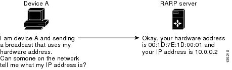
Reverse ARP (RARP) as defined by RFC 903 works the same way as ARP, except that the RARP request packet requests an IP address instead of a MAC address. RARP often is used by diskless workstations because this type of device has no way to store IP addresses to use when they boot. The only address that is known is the MAC address because it is burned into the hardware.
Use of RARP requires an RARP server on the same network segment as the router interface. Figure 2-2 illustrates how RARP works.
RARP has several limitations. Because of these limitations, most businesses use DHCP to assign IP addresses dynamically. DHCP is cost effective and requires less maintenance than RARP. The following are the most important limitations:
- Since RARP uses hardware addresses, if the internetwork is large with many physical networks, a RARP server must be on every segment with an additional server for redundancy. Maintaining two servers for every segment is costly.
- Each server must be configured with a table of static mappings between the hardware addresses and IP addresses. Maintenance of the IP addresses is difficult.
- RARP only provides IP addresses of the hosts and not subnet masks or default gateways.
Proxy ARP
Proxy ARP enables a device that is physically located on one network appear to be logically part of a different physical network connected to the same device or firewall. Proxy ARP allows you to hide a device with a public IP address on a private network behind a router and still have the device appear to be on the public network in front of the router. By hiding its identity, the router accepts responsibility for routing packets to the real destination. Proxy ARP can help devices on a subnet reach remote subnets without configuring routing or a default gateway.
When devices are not in the same data link layer network but in the same IP network, they try to transmit data to each other as if they are on the local network. However, the router that separates the devices does not send a broadcast message because routers do not pass hardware-layer broadcasts and the addresses cannot be resolved.
When you enable Proxy ARP on the device and it receives an ARP request, it identifies the request as a request for a system that is not on the local LAN. The device responds as if it is the remote destination for which the broadcast is addressed, with an ARP response that associates the device’s MAC address with the remote destination's IP address. The local device believes that it is directly connected to the destination, while in reality its packets are being forwarded from the local subnetwork toward the destination subnetwork by their local device. By default, Proxy ARP is disabled.
Local Proxy ARP
You can use local Proxy ARP to enable a device to respond to ARP requests for IP addresses within a subnet where normally no routing is required. When you enable local Proxy ARP, ARP responds to all ARP requests for IP addresses within the subnet and forwards all traffic between hosts in the subnet. Use this feature only on subnets where hosts are intentionally prevented from communicating directly by the configuration on the device to which they are connected.
Gratuitous ARP
Gratuitous ARP sends a request with an identical source IP address and a destination IP address to detect duplicate IP addresses. Cisco NX-OS Release 4.0(3) and later releases support enabling or disabling gratuitous ARP requests or ARP cache updates.
Glean Throttling
When forwarding an incoming IP packet in a line card, if the Address Resolution Protocol (ARP) request for the next hop is not resolved, the line card forwards the packets to the supervisor (glean throttling). The supervisor resolves the MAC address for the next hop and programs the hardware.
The Cisco Nexus 7000 Series device hardware has glean rate limiters to protect the supervisor from the glean traffic. If the maximum number of entries is exceeded, the packets for which the ARP request is not resolved continues to be processed in the software instead of getting dropped in the hardware.
When an ARP request is sent, the software adds a /32 drop adjacency in the hardware to prevent the packets to the same next-hop IP address to be forwarded to the supervisor. When the ARP is resolved, the hardware entry is updated with the correct MAC address. If the ARP entry is not resolved before a timeout period, the entry is removed from the hardware.
Path MTU Discovery
Path maximum transmission unit (MTU) discovery is a method for maximizing the use of available bandwidth in the network between the endpoints of a TCP connection. It is described in RFC 1191. Existing connections are not affected when this feature is turned on or off.
Note Please ensure you enable ip unreachables command between TCP endpoints for the Path MTU discovery feature to work correctly.
ICMP
You can use the Internet Control Message Protocol (ICMP) to provide message packets that report errors and other information that is relevant to IP processing. ICMP generates error messages, such as ICMP destination unreachable messages, ICMP Echo Requests (which send a packet on a round trip between two hosts) and Echo Reply messages. ICMP also provides many diagnostic functions and can send and redirect error packets to the host. By default, ICMP is enabled.
Some of the ICMP message types are as follows:
- Network error messages
- Network congestion messages
- Troubleshooting information
- Timeout announcements
Note ICMP redirects are disabled on interfaces where the local proxy ARP feature is enabled.
Virtualization Support
IPv4 supports virtual routing and forwarding (VRF) instances. VRFs exist within virtual device contexts (VDCs). By default, Cisco NX-OS places you in the default VDC and default VRF unless you specifically configure another VDC and VRF. For more information, see the Cisco NX-OS Virtual Device Context Configuration Guide and see Chapter14, “Configuring Layer 3 Virtualization”
Licensing Requirements for IPv4
The following table shows the licensing requirements for this feature:
Guidelines and Limitations for IPv4
IPv4 has the following configuration guidelines and limitations:
Default Settings
Table 2-1 lists the default settings for IP parameters.
Configuring IPv4
This section includes the following topics:
- Configuring IPv4 Addressing
- Configuring Multiple IP Addresses
- Configuring a Static ARP Entry
- Configuring Proxy ARP
- Configuring Local Proxy ARP
- Configuring Gratuitous ARP
- Configuring Path MTU Discovery
- Configuring IP Packet Verification
- Configuring IP Directed Broadcasts
- Configuring IP Glean Throttling
- Configuring the Hardware IP Glean Throttle Maximum
- Configuring a Hardware IP Glean Throttle Timeout
- Configuring the Hardware IP Glean Throttle Syslog
Note If you are familiar with the Cisco IOS CLI, be aware that the Cisco NX-OS commands for this feature might differ from the Cisco IOS commands that you would use.
DETAILED STEPS
This example shows how to assign an IPv4 address:
switch(config)# interface ethernet 2/3
Configuring Multiple IP Addresses
You can only add secondary IP addresses after you configure primary IP addresses.
DETAILED STEPS
Configuring a Static ARP Entry
You can configure a static ARP entry on the device to map IP addresses to MAC hardware addresses, including static multicast MAC addresses.
DETAILED STEPS
Associates an IP address with a MAC address as a static entry. |
||
This example shows how to configure a static ARP entry:
switch(config)# interface ethernet 2/3
Configuring Proxy ARP
You can configure Proxy ARP on the device to determine the media addresses of hosts on other networks or subnets.
DETAILED STEPS
This example shows how to configure Proxy ARP:
switch(config)# interface ethernet 2/3
DETAILED STEPS
This example shows how to configure Local Proxy ARP:
switch(config)# interface ethernet 2/3
DETAILED STEPS
Enables gratuitous ARP on the interface. The default is enabled. |
||
This example shows how to disable gratuitous ARP requests:
switch(config)# interface ethernet 2/3
Configuring IP Packet Verification
Cisco NX-OS supports an Intrusion Detection System (IDS) that checks for IP packet verification. You can enable or disable these IDS checks.
To enable IDS checks, use the following commands in global configuration mode:
Use the show hardware forwarding ip verify command to display the IP packet verification configuration.
Configuring IP Directed Broadcasts
An IP directed broadcast is an IP packet whose destination address is a valid broadcast address for some IP subnet but which originates from a node that is not itself part of that destination subnet.
A device that is not directly connected to its destination subnet forwards an IP directed broadcast in the same way it forwards unicast IP packets destined to a host on that subnet. When a directed broadcast packet reaches a device that is directly connected to its destination subnet, that packet is broadcast on the destination subnet. The destination address in the IP header of the packet is rewritten to the configured IP broadcast address for the subnet, and the packet is sent as a link-layer broadcast.
If directed broadcast is enabled for an interface, incoming IP packets whose addresses identify them as directed broadcasts intended for the subnet to which that interface is attached are broadcasted on that subnet. You can optionally filter those broacasts through an IP access list such that only those packets that pass through the access list are broadcasted on the subnet.
To enable IP directed broadcasts, use the following command in interface configuration mode:
Configuring IP Glean Throttling
Cisco NX-OS software supports glean throttling rate limiters to protect the supervisor from the glean traffic.
You can enable IP glean throttling.
Note We recommend that you configure the IP glean throttle feature by using the hardware ip glean throttle command to filter the unnecessary glean packets that are sent to the supervisor for ARP resolution for the next hops that are not reachable or do not exist. IP glean throttling boosts software performance and helps to manage traffic more efficiently.
DETAILED STEPS
This example shows how to enable IP glean throttling:
Configuring the Hardware IP Glean Throttle Maximum
You can limit the maximum number of drop adjacencies that are installed in the Forwarding Information Base (FIB).
SUMMARY STEPS
2. hardware ip glean throttle maximum count
DETAILED STEPS
Configures the number of drop adjacencies that are installed in the FIB. |
||
|
The default value is 1000. The range is from 0 to 32767 entries. |
||
This example shows how to limit the maximum number of drop adjacencies that are installed in the FIB:
Configuring a Hardware IP Glean Throttle Timeout
You can configure a timeout for the installed drop adjacencies to remain in the FIB.
SUMMARY STEPS
2. hardware ip glean throttle maximum timeout timeout-in-sec
3. no hardware ip glean throttle maximum timeout timeout-in-sec
DETAILED STEPS
This example shows how to configure a timeout for the drop adjacencies that are installed.
switch(config)# hardware ip glean throttle maximum timeout 300
Configuring the Hardware IP Glean Throttle Syslog
You can generate a syslog if the number of packets that get dropped for a specific flow exceeds the configured packet count.
SUMMARY STEPS
2. hardware ip glean throttle syslog pck-count
DETAILED STEPS
This example shows how to generate a syslog if the number of packets that get dropped for a specific flow exceeds the configured packet count:
Verifying the IPv4 Configuration
To display the IPv4 configuration information, perform one of the following tasks:
Configuration Examples for IPv4
The N7K-F132-15 module only runs Layer 2 switching. So, when you have both this module and an M Series module in one Nexus 7000 Series chassis and you are performing Layer 3 procedures, the system uses proxy routing. You can also configure proxy routing.
This section includes the following topics:
- Example: Reserving All Ports on a Module for Proxy Routing
- Example: Reserving Ports for Proxy Routing
- Example: Excluding Ports From Proxy Routing
Example: Reserving All Ports on a Module for Proxy Routing
This example shows how to reserve all ports on a module for proxy routing.
Step 1 Determine which modules are present in the device.
The F1 module is in Slot 8, and the M1 modules are in Slots 1 - 3.
Step 2 Determine which ports are available in the VDC.
Step 3 Determine which ports are available for proxy routing.
Note Ports are listed in their respective port-groups.
Step 4 Reserve a module for unicast and multicast proxy routing.
Step 5 Verify this configuration.
Example: Reserving Ports for Proxy Routing
This example shows how to reserve some ports on a module for proxy routing.
Step 1 Reserve a subset of ports on a module.
This example reserves a subset of ports from a port group.
Step 2 Verify this configuration.
Note All ports in a port group are reserved for proxy routing.
Example: Excluding Ports From Proxy Routing
This example shows how to exclude some ports on a module from proxy routing.
Step 1 Exclude a subset of ports on a module.
Step 2 Verify this configuration.
Note All ports in the port group are excluded from proxy routing.
Additional References
For additional information related to implementing IP, see the following sections:
Feature History for IP
Table 2-2 lists the release history for this feature.
 Feedback