Cisco DCNM Installation Guide, Release 10.0(x)
Bias-Free Language
The documentation set for this product strives to use bias-free language. For the purposes of this documentation set, bias-free is defined as language that does not imply discrimination based on age, disability, gender, racial identity, ethnic identity, sexual orientation, socioeconomic status, and intersectionality. Exceptions may be present in the documentation due to language that is hardcoded in the user interfaces of the product software, language used based on RFP documentation, or language that is used by a referenced third-party product. Learn more about how Cisco is using Inclusive Language.
- Updated:
- May 11, 2016
Chapter: Prerequisites
Prerequisites for Programmable Fabric Installation
This sections details the various prerequisites, hardware and software requirements that you must equip with, before installing Programmable Fabric DCNM. This section contains prerequisites for the following:
Prerequisites for DCNM Open Virtual Appliance
Before you install the Cisco DCNM Open Virtual Appliance, you will need to meet following software and database
- VMware vCenter Server 5.1.0 or v5.5 that is running on a Windows server (or alternatively, running as a virtual appliance)
- VMWare ESXi 5.1, 5.5 or 6.0 host imported into vCenter 5.1, 5.5 or 6.0, respectively
- Two port groups on the ESXi host:
– Enhanced Fabric Management Network

Note The DCNM Open Virtual Appliance cannot be deployed by connecting the vSphere client directly to the ESXi server.
- Determine the number of switches in your Cisco Programmable Fabric that will be managed by the Cisco DCNM Open Virtual Appliance.
Note Once you start using the PostgreSQL database that is built in to the Cisco DCNM Open Virtual Appliance, you cannot migrate the data to an Oracle database.
Note To accommodate for HA application functions, additional prerequisites are required.
Prerequisites for DCNM ISO Virtual Appliance
You have to setup the host or the hypervisor before you install the Cisco DCNM ISO Virtual Appliance. Based on the requirement, setup the host.
You can setup one of the following hosts to install the DCNM ISO Virtual Appliance.
VMware ESXi
The host machine is installed with ESXi and two port groups are created—one for EFM network and the other for DCNM Management network.
Kernel-based Virtual Machine (KVM)
The host machine is installed with Red Hat Enterprise Linux 6.x with KVM libraries and Graphical User Interface (GUI) access. The GUI allows to access the Virtual Machine Manager, to deploy and manage the Cisco DCNM Virtual Appliances. Two networks are created—EFM network and DCNM Management network. Typically, the DCNM management network is bridged to gain access from other subnets. Refer the KVM documentation on how to create different types of networks.
Note KVM on other platforms like CentOS/Ubuntu will not be supported as it increases the compatibility matrix.
Prerequisites for non-Programmable Fabric Installation
This sections details the various prerequisites, hardware and software requirements that you must equip with, before installing Cisco non-Programmable Fabric DCNM. This section contains prerequisites for the following:
- General Prerequisites for Installing the Cisco DCNM on Windows and Linux
- Prerequisites for Windows Installer
- Prerequisites for Linux RHEL Server
- Prerequisites for non-Programmable Fabric Open Virtual Appliance
- Prerequisites for non-Programmable Fabric ISO Virtual Appliance
Before you begin
Before you can install Cisco DCNM, ensure that the Cisco DCNM system meets the following prerequisites:
- Before installing Cisco DCNM, ensure that the host name is mapped with the IP address in the hosts file under the following location:
– Microsoft Windows–C:\WINDOWS\system32\drivers\etc\hosts
Note If Oracle RAC is chosen as the database for Cisco DCNM, ensure that the database host IP addresses and virtual IP addresses are added to the hosts file with their host-names.
- For RHEL, the maximum shared memory size must be 256 MB or more. To configure the maximum shared memory to 256 MB, use the following command:
sysctl -w kernel.shmmax=268435456
This setting, kernel.shmmax=268435456, should be saved in the /etc/sysctl.conf file. If this setting is not present or if it is less than 268435456, the Cisco DCNM server will fail after the server system is rebooted. For more information, visit the following URL:
http://www.postgresql.org/docs/8.3/interactive/kernel-resources.html
The server system must be registered with the DNS servers. The server hosting DCNM application must be dedicated to run DCNM alone and must not be shared with any other applications which utilizes memory and system resources.
- While using Remote PostgreSQL Database server, ensure that the Cisco DCNM Host IP addresses are added to the pg_hba.conf file present in the PostgreSQL installation directory. After the entries are added, restart the DB.
- Users installing Cisco DCNM must have full administrator privileges to create user accounts and start services. Users should also have access to all ports. These ports are used by Cisco DCNM Server and the PostgreSQL database: 1098, 1099, 4444, 4445, 8009, 8083, 8090, 8092, 8093, 514, 5432.
- When you connect to the server for the first time, Cisco DCNM checks to see if you have the correct Sun Java Virtual Machine version installed on your local workstation. Cisco DCNM desktop clients look for version 1.7(x) during installation. If required, install the Sun Java Virtual Machine software.
Note When launching the Cisco DCNM installer, the console command option is not supported.
Note Using the Cisco DCNM installer in GUI mode requires that you must log in to the remote server using VNC or XWindows. Using Telnet or SSH to install Cisco DCNM in GUI mode is not possible.
Before you can use Cisco DCNM to manage network switches, you must complete the following tasks:
- Install a supervisor module on each switch that you want to manage.
- Configure the supervisor module with the following values using the setup routine or the CLI:
– IP address assigned to the mgmt0 interface
– SNMP credentials (v3 user name and password or v1/v2 communities), maintaining the same user name and password for all the switches in the fabric.
Initial Setup Routine
The first time that you access a switch in the Cisco MDS 9000 Family, it runs a setup program that prompts you for the IP address and other configuration information necessary for the switch to communicate over the supervisor module Ethernet interface. This information is required to configure and manage the switch. All Cisco MDS 9000 Family switches have the network administrator as a default user (Admin). You cannot change the default user at any time. You must explicitly configure a strong password for any switch in the Cisco MDS 9000 Family. The setup scenario differs based on the subnet to which you are adding the new switch:
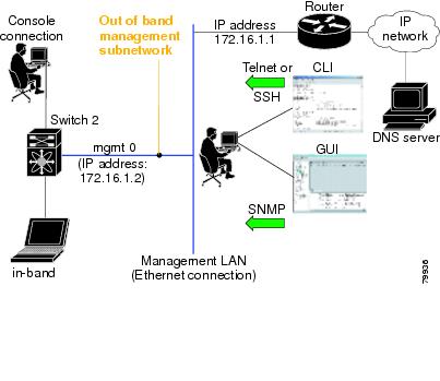
- Out-of-band management—This feature provides a connection to the network through a supervisor module front panel Ethernet port.
- In-band management—This feature provides IP over Fibre Channel (IPFC) to manage the switches. The in-band management feature is transparent to the network management system (NMS).
Note IP address for an MDS9000 switch can be set via CLI or USB key or POAP
Preparing to Configure the Switch
Before you configure a switch in the Cisco MDS 9000 Family for the first time, you need the following information:
– Creating a password for the administrator (required).
– Creating an additional login account and password (optional).
- IP address for the switch management interface—The management interface can be an out-of-band Ethernet interface or an in-band Fibre Channel interface (recommended).
- Subnet mask for the switch's management interface (optional).
- IP addresses, including:
– Destination prefix, destination prefix subnet mask, and next-hop IP address if you want to enable IP routing. Also, provide the IP address of the default network (optional).
– Otherwise, provide an IP address of the default gateway (optional).
- SSH service on the switch—To enable this optional service, select the type of SSH key (dsa/rsa/rsa1) and number of key bits (768 to 2048).
- DNS IP address (optional).
- Default domain name (optional).
- NTP server IP address (optional).
- SNMP community string (optional).
- Switch name—This is your switch prompt (optional).
Note Be sure to configure the IP route, the IP default network address, and the IP default gateway address to enable SNMP access. If IP routing is enabled, the switch uses the IP route and the default network IP address. If IP routing is disabled, the switch uses the default gateway IP address.
Note You should verify that the Cisco DCNM-SAN Server host name entry exists on the DNS server, unless the Cisco DCNM-SAN Server is configured to bind to a specific interface during installation.
Default Login
All Cisco MDS 9000 Family switches have the network administrator as a default user (Admin). You cannot change the default user at any time (see the Security Configuration Guide, Cisco DCNM for SAN).
You have an option to enforce a secure password for any switch in the Cisco MDS 9000 Family. If a password is trivial (short, easy-to-decipher), your password configuration is rejected. Be sure to configure a secure password (see the Security Configuration Guide, Cisco DCNM for SAN). If you configure and subsequently forget this new password, you have the option to recover this password (see the Security Configuration Guide, Cisco DCNM for SAN).
Note The password can contain a combination of alphabets, numeric, and special characters. The supportive special characters are dot (.), plus (+), underscore (_), and hyphen (-).
Setup Options
The setup scenario differs based on the subnet to which you are adding the new switch. You must configure a Cisco MDS 9000 Family switch with an IP address to enable management connections from outside of the switch (see Figure 2-1).
Note Some concepts such as out-of-band management and in-band management are briefly explained here. These concepts are explained in more detail in subsequent chapters.
Figure 2-1 Management Access to Switches
Assigning Setup Information
This section describes how to initially configure the switch for both out-of-band and in-band management.
Note Press Ctrl + C at any prompt to skip the remaining configuration options and proceed with what is configured until that point. Entering a new password for the administrator is a requirement and cannot be skipped.

Tip If you do not wish to answer a previously configured question, or if you wish to skip answers to any questions, press Enter. If a default answer is not available (for example, switch name), the switch uses what was previously configured and skips to the next question.
Configuring Out-of-Band Management
You can configure both in-band and out-of-band configuration together by entering Yes in both Step 11 c and Step 11 d in the following procedure.
DETAILED STEPS
Step 1 Power on the switch. Switches in the Cisco MDS 9000 Family boot automatically.
Step 2 Enter Yes to enforce a secure password.
a. Enter the administrator password.
Note The password can contain a combination of alphabets, numeric, and special characters. The supportive special characters are dot (.), plus (+), underscore (_), and hyphen (-).
b. Confirm the administrator password.
Tip If a password is trivial (short, easy to decipher), your password configuration is rejected. Be sure to configure a secure password as shown in the sample configuration. Passwords are case sensitive.
Step 3 Enter yes to enter the setup mode.
Note This setup utility guides you through the basic configuration of the system. Setup configures only enough connectivity for management of the system.
The setup utility guides you through the basic configuration process. Press Ctrl + C at any prompt to end the configuration process.
Step 4 Enter the new password for the administrator (Admin is the default).
Step 5 Enter yes (no is the default) to create additional accounts.
While configuring your initial setup, you can create an additional user account (in the network administrator role) in addition to the administrator’s account. See the Security Configuration Guide, Cisco DCNM for SAN for information on default roles and permissions.
Note User login IDs must contain non-numeric characters.
a. Enter the user login ID [administrator].
The password can contain a combination of alphabets, numeric, and special characters. The supportive special characters are dot (.), plus (+), underscore (_), and hyphen (-).
Step 6 Enter yes (no is the default) to create an SNMPv3 account.
a. Enter the username (Admin is the default).
b. Enter the SNMPv3 password (minimum of eight characters). The default is admin123.
Step 7 Enter yes (no is the default) to configure the read-only or read-write SNMP community string.
a. Enter the SNMP community string.
Step 8 Enter a name for the switch.
Step 9 Enter yes (yes is the default) to configure out-of-band management.
a. Enter the mgmt0 IP address.
b. Enter the mgmt0 subnet mask.
Step 10 Enter yes (yes is the default) to configure the default gateway (recommended).
a. Enter the default gateway IP address.
Step 11 Enter yes ( no is the default) to configure advanced IP options such as in-band management, static routes, default network, DNS, and domain name.
a. Enter no (no is the default) at the in-band management configuration prompt.
b. Enter yes (no is the default) to enable IP routing capabilities.
c. Enter yes (no is the default) to configure a static route (recommended).
Enter the destination prefix mask.
Enter the next-hop IP address.
Note Be sure to configure the IP route, the default network IP address, and the default gateway IP address to enable SNMP access. If IP routing is enabled, the switch uses the IP route and the default network IP address. If IP routing is disabled, the switch uses the default gateway IP address.
d. Enter yes (no is the default) to configure the default network (recommended).
Enter the default network IP address.
Note The default network IP address is the destination prefix provided in Step 11c .
e. Enter yes (no is the default) to configure the DNS IP address.
f. Enter yes (default is no) to configure the default domain name.
Enter the default domain name.
Step 12 Enter yes (no is the default) to enable Telnet service.
Step 13 Enter yes (no is the default) to enable the SSH service.
Step 14 Enter the SSH key type.
Step 15 Enter the number of key bits within the specified range.
Step 16 Enter yes (no is the default) to configure the NTP server.
a. Enter the NTP server IP address.
Step 17 Enter noshut (shut is the default) to configure the default switch port interface to the shut state.
Step 18 Enter on (on is the default) to configure the switch port trunk mode.
Step 19 Enter no (no is the default) to configure switchport port mode F.
Step 20 Enter permit (deny is the default) to deny a default zone policy configuration.
This step permits traffic flow to all members of the default zone.
Step 21 Enter yes (no is the default) to disable a full zone set distribution (see the Fabric Configuration Guide, Cisco DCNM for SAN). Disables the switch-wide default for the full zone set distribution feature.
You see the new configuration. Review and edit the configuration that you have just entered.
Step 22 Enter no (no is the default) if you are satisfied with the configuration.
Step 23 Enter yes (yes is default) to use and save this configuration:

Configuring In-Band Management
The in-band management logical interface is VSAN 1. This management interface uses the Fibre Channel infrastructure to transport IP traffic. An interface for VSAN 1 is created on every switch in the fabric. Each switch should have its VSAN 1 interface configured with an IP address in the same subnetwork. A default route that points to the switch that provides access to the IP network should be configured on every switch in the Fibre Channel fabric (see Fabric Configuration Guide, Cisco DCNM for SAN).
Note You can configure both in-band and out-of-band configuration together by entering Yes in both Step 9c and Step 9d in the following procedure.
DETAILED STEPS
Step 1 Power on the switch. Switches in the Cisco MDS 9000 Family boot automatically.
Step 2 Enter the new password for the administrator.
Tip If a password is trivial (short, easy-to-decipher), your password configuration is rejected. Be sure to configure a strong password as shown in the sample configuration. Passwords are case sensitive. The password can contain a combination of alphabets, numeric, and special characters. The supportive special characters are dot (.), plus (+), underscore (_), and hyphen (-).
Step 3 Enter yes to enter the setup mode.
The setup utility guides you through the basic configuration process. Press Ctrl-C at any prompt to end the configuration process.
Step 4 Enter no (no is the default) if you do not wish to create additional accounts.
Step 5 Configure the read-only or read-write SNMP community string.
a. Enter no (no is the default) to avoid configuring the read-only SNMP community string.
Step 6 Enter a name for the switch.
Note The switch name is limited to 32 alphanumeric characters. The default is switch.
Step 7 Enter no (yes is the default) at the configuration prompt to configure out-of-band management.
Step 8 Enter yes (yes is the default) to configure the default gateway.
a. Enter the default gateway IP address.
Step 9 Enter yes ( no is the default) to configure advanced IP options such as in-band management, static routes, default network, DNS, and domain name.
a. Enter yes (no is the default) at the in-band management configuration prompt.
b. Enter no (yes is the default) to enable IP routing capabilities.
c. Enter no (yes is the default) to configure a static route.
d. Enter no (yes is the default) to configure the default network.
e. Enter no (yes is the default) to configure the DNS IP address.
f. Enter no (no is the default) to skip the default domain name configuration.
Step 10 Enter no (yes is the default) to disable Telnet service.
Step 11 Enter yes (no is the default) to enable the SSH service.
Step 12 Enter the SSH key type (see the Security Configuration Guide, Cisco DCNM for SAN) that you would like to generate.
Step 13 Enter the number of key bits within the specified range.
Step 14 Enter no (no is the default) to configure the NTP server.
Step 15 Enter shut (shut is the default) to configure the default switch port interface to the shut state.
Note The management Ethernet interface is not shut down at this point—only the Fibre Channel, iSCSI, FCIP, and Gigabit Ethernet interfaces are shut down.
Step 16 Enter auto (off is the default) to configure the switch port trunk mode.
Step 17 Enter deny (deny is the default) to deny a default zone policy configuration.
This step denies traffic flow to all members of the default zone.
Step 18 Enter no (no is the default) to disable a full zone set distribution.
This step disables the switch-wide default for the full zone set distribution feature.
You see the new configuration. Review and edit the configuration that you have just entered.
Step 19 Enter no (no is the default) if you are satisfied with the configuration.
Step 20 Enter yes (yes is default) to use and save this configuration.
Using the setup Command
To make changes to the initial configuration at a later time, you can enter the setup command in EXEC mode.
The setup utility guides you through the basic configuration process.
Starting a Switch in the Cisco MDS 9000 Family
The following procedure is a review of the tasks you should have completed during hardware installation, including starting up the switch. These tasks must be completed before you can configure the switch.
Note You must use the CLI for initial switch start up.
DETAILED STEPS
Step 1 Verify the following physical connections for the new Cisco MDS 9000 Family switch:
- The console port is physically connected to a computer terminal (or terminal server).
- The management 10/100 Ethernet port (mgmt0) is connected to an external hub, switch, or router.
See the Cisco MDS 9000 Family Hardware Installation Guide (for the required product) for more information.
Tip Save the host ID information for future use (for example, to enable licensed features). The host ID information is provided in the Proof of Purchase document that accompanies the switch.
Step 2 Verify that the default console port parameters are identical to those of the computer terminal (or terminal server) attached to the switch console port:
Step 3 Power on the switch. The switch boots automatically and the switch# prompt appears in your terminal window.
Accessing the Switch
After initial configuration, you can access the switch in one of the three ways:
- Serial console access—You can use a serial port connection to access the CLI.
- In-band IP (IPFC) access—You can use Telnet or SSH to access a switch in the Cisco MDS 9000 Family or use SNMP to connect to a Cisco DCNM-SAN application.
- Out-of-band (10/100BASE-T Ethernet) access—You can use Telnet or SSH to access a switch in the Cisco MDS 9000 Family or use SNMP to connect to a Cisco DCNM-SAN application.
After initial configuration, you can access the switch in one of three ways (see Figure 2-2):
- Serial console access—You can use a serial port connection to access the CLI.
- In-band IP (IPFC) access—You can use Telnet or SSH to access a switch in the Cisco MDS 9000 Family or use Cisco DCNM-SAN to access the switch.
- Out-of-band (10/100BASE-T Ethernet) access—You can use Telnet or SSH to access a switch in the Cisco MDS 9000 Family or use Cisco DCNM-SAN to access the switch.
Figure 2-2 Switch Access Options
Prerequisites for Windows Installer
- During the initial installation, disable all security and anti virus tools that are running on your Windows server.
- Do not run any other management applications on the Cisco DCNM server or the Cisco DCNM database server.
- Before installing Cisco DCNM, ensure that the host name is mapped with the IP address in the hosts file under the location C:\WINDOWS\system32\drivers\etc\hosts.
- On Windows, remote Cisco DCNM installations or upgrades should be done through the console using VNC or through the Remote Desktop Client (RDC) in console mode (ensuring RDC is used with the /Console option). This process is very important if the default PostgreSQL database is used with Cisco DCNM, because this database requires the local console for all installations and upgrades.
- Before installing Cisco DCNM on a Windows Vista or Windows 2008 server system, turn the User Account Control (UAC) off. To turn off UAC, choose Start > Control Panel > User Accounts > Turn User Account Control on or off, clear the Use User Account Control (UAC) to help protect your computer check box, and then click OK. Click Restart Now to apply the change.
- Telnet Client application is not installed by default on Microsoft Windows Vista. To install Telnet Client, choose Start > Programs > Control Panel > Click Turn Windows features on or off (if you have UAC turned on, you need to give it the permission to continue). Check the Telnet Client check box and then click OK.
- You can run CiscoWorks on the same PC as Cisco DCNM even though the Java requirements are different. When installing the later Java version for Cisco DCNM, make sure that it does not overwrite the earlier Java version required for CiscoWorks. Both versions of Java can coexist on your PC.
Prerequisites for Linux RHEL Server
For RHEL, the maximum shared memory size must be 256 MB or more. To configure the maximum shared memory to 256 MB, use the following command:
sysctl -w kernel.shmmax=268435456
This setting, kernel.shmmax=268435456, should be saved in the /etc/sysctl.conf file. If this setting is not present or if it is less than 268435456, the Cisco DCNM server will fail after the server system is rebooted. For more information, visit the following URL:
http://www.postgresql.org/docs/8.4/interactive/kernel-resources.html
The server system must be registered with the DNS servers. No other programs are running on the server.
Ensure that you select English as the preferred language during RHEL installation.
Antivirus exclusion
Scanning the Cisco DCNM includes the scanning of the database files. This process will hamper the performance on the DCNM while operation. While scanning the Cisco DCNM on Linux RHEL server, exclude the directory /usr/local/cisco/dcm/db and /var/lib/dcnm.
For more information, refer to https://wiki.postgresql.org/wiki/Running_%26_Installing_PostgreSQL_On_Native_Windows#Antivirus_software .
Note We recommend you to stop Anti-Virus scanning while installing DCNM because the port being used or blocked might cause failures. After the installation, you can enable or install Anti-Virus application with specific guidelines to avoid DCNM directories as part of the scan.
This recommendation is also applicable to DCNM installations in an ISO/OVA format.
Prerequisites for non-Programmable Fabric Open Virtual Appliance
For information on prerequisites to install DCNM Open Virtual Appliance, refer to Prerequisites for DCNM Open Virtual Appliance.
Prerequisites for non-Programmable Fabric ISO Virtual Appliance
For information on prerequisites to install ISO Virtual Appliance, refer to Prerequisites for DCNM ISO Virtual Appliance.
Supported Software
Note For the latest information on supported software, see the Cisco DCNM Release Notes, Release 10.0(x).
The following are the supported software for Cisco DCNM 10.0(x):
Supported Software for DCNM Windows/Linux Installers
– Cisco DCNM Server is distributed with Java JRE 1.7.0_72. The DCNM installer installs JRE
– 1.7.0_72 to the following directory: DCNM_root_directory/java/jre1.7
– Cisco DCNM Client has been validated with Java versions 1.7.0_55 and 1.7.0_72.
– Microsoft Windows 2008 R2 SP2 (64-bit only)
Supported Software for DCNM Virtual Appliances (OVA/ISO)
– Oracle11g Express (XE), Standard, and Enterprise Editions, and Oracle 11g Real Application
– Oracle 12c Enterprise Edition (Conventional)–Non-pluggable Installation
– Oracle 12c RAC–Non-pluggable installation
Note Customers are responsible for all support associated with Oracle database, including maintenance, troubleshooting, and recovery. Cisco recommends that customers perform regular database backups, either daily or weekly, to ensure that all data is preserved.
Oracle Database for DCNM Servers
This section details about the database required for the installation of DCNM server.
Note This section is not applicable for Cisco DCNM Native HA installation.
Cisco DCNM supports the following databases:
You can change from the local database to an external Oracle database, if required. For instructions, see Change from Local Database to an External Database.
Note Cisco DCNM is configured with AL32UTF8 character set.
This section contains the following:
- Oracle SQL*Plus Command-Line Tool
- init.ora File
- Backing up the Oracle Database
- Preparing the Oracle Database
- Database for HA environment
- Database for Federation Setup
- Antivirus exclusion
Note The Cisco DCNM Database size is not limited and increases based on the number of nodes and ports that the DCNM manages with Performance Manager Collections enabled. You cannot restrict the database size. Cisco recommends that you use Oracle SE or Enterprise edition, instead of Oracle XE, due to table space limitations.
Oracle SQL*Plus Command-Line Tool
The Oracle database procedures in this section require the use of the SQL*Plus command-line tool. The SQL*Plus executable is typically installed in the bin directory under the Oracle home directory.
Linux Environment Variables
If you are using Linux, before you use the SQL*Plus command-line tool, ensure that the ORACLE_HOME and ORACLE_SID environment variables are set to correct values. For example, if you are using Oracle 11g on Linux, the following commands set the environment variables to the default Oracle home directory and SID if you are using a bash shell:
init.ora File
The init.ora file specifies startup parameters. The default name and location of the file is platform specific, as shown in Table 2-1 .
The init.ora file should contain only one line, which is the full path of the server parameter file, as shown in Table 2-2 .
Backing up the Oracle Database
Copy the oracle backup/restore script from the Cisco DCNM server directory DCNM_SERVER_Install/dcm/dcnm/bin.
For Linux, the script name is backup-remote-oracledb.sh/restore-remote-oracledb.sh and edit the DB_HOME variable to point to the Oracle installation.
For Windows, the script name is backup-remote-oracledb.bat/restore-remote-oracledb.bat and edit DB_HOME variable to point to the Oracle installation.
Use the following path for Oracle DBHOME:
Note Replace /usr/lib/oracle with the Oracle installation path.
Note Replace C:\oraclexe with the Oracle installation path.
DETAILED STEPS
Step 1 (Oracle 10g only) Increase the SYSTEM tablespace to 2 GB from the default of 1 GB. For more information, see the “Increasing the SYSTEM Tablespace” section.
Step 2 Increase the number of sessions and processes to 150 each. For more information, see the “Increasing the Number of Sessions and Processes to 150 Each” section.
Step 3 Increase the number of open cursors to 1000. For more information, see the “Increasing the Number of Open Cursors to 1000” section.
DETAILED STEPS
Step 1 Run the SQL*Plus executable.
Step 2 Enter the connect command.
Step 3 Enter the database administrator username.
Step 4 Enter the password for the username that you specified.
For example, if the Oracle administrator username is system and the password is oracle, you would log in as follows:
For more information about using SQL*Plus, see the documentation for the Oracle database version that you are using.
DETAILED STEPS
Step 1 Use the SQL*Plus command-line tool to log in to the Oracle database. For more information, see the “Oracle SQL*Plus Command-Line Tool” section.
Step 2 Enter the following command:
Step 3 Enter the following command:
where file_name is the filename from the output of the select command in Step 2.
The SYSTEM tablespace is increased.
Step 4 Enter the exit command.
Increasing the Number of Sessions and Processes to 150 Each
For each DCNM instance configured in the same Oracle database, the number of cursors and processes must be increased to more than the 150 and 1000.
For example, if two DCNM standalone (non HA) instances are configured to use the same Oracle database, the cursors and process must be increased to 300 and 2000 approximately, depending on any performance degradation or SQL Exception errors occurred during normal operations of either of the DCNM instances.
DETAILED STEPS
Step 1 Ensure that the init.ora file exists and that it contains the single line that is applicable for your Oracle database installation. If there are additional lines, remove them.
For more information, see the “init.ora File” section.
Step 2 Use the SQL*Plus command-line tool to log in to the Oracle database. For more information, see the “Oracle SQL*Plus Command-Line Tool” section.
Step 3 Shut down the system by entering the shutdown command. If the command fails, use the shutdown abort command.
Step 4 Enter the following command:
where init_file_name is the init.ora filename for your Oracle database installation. For more information, see the “init.ora File” section.
Step 5 Set the number of sessions to 150 by entering the following command:
Step 6 Set the number of processes to 150 by entering the following command:
Step 7 Shut down the system by entering the shutdown command. If the command fails, use the shutdown abort command.
Step 8 Start up the system by entering the startup command.
Step 9 Verify that the number of sessions and processes is changed to 150 by entering the following command:
Step 10 Exit by entering the exit command.
DETAILED STEPS
Step 1 Ensure that the init.ora file exists and that it contains the single line that is applicable for your Oracle database installation. If there are additional lines in the file, remove them.
For more information, see the “init.ora File” section.
Step 2 Use the SQL*Plus command-line tool to log in to the Oracle database. For more information, see the “Oracle SQL*Plus Command-Line Tool” section.
Step 3 Shut down the system by entering the shutdown command. If the command fails, use the shutdown abort command.
Step 4 Enter the following command:
where init_file_name is the init.ora filename for your Oracle database installation. For more information, see the “init.ora File” section.
Step 5 Set the number of open cursors to 1000 by entering the following command:
Step 6 Shut down the system by entering the shutdown command. If the command fails, use the shutdown abort command.
Step 7 Start up the system by entering the startup command.
Step 8 Verify that the number of open cursors is changed to 1000 by entering the following command:
Step 9 Exit by entering the exit command.
Creating an Oracle DB User using the Command Prompt
To create an Oracle DB user using the command prompt, follow these steps:
Note Ensure you set the Oracle_SID and Oracle_Home and enter the values for the DB Username and password fields.
Note When a DBA account cannot be created, an account with DML/DDL/schema privilege is sufficient.
Database for HA environment
If you need High Availability (HA) for DCNM database, utilize the Oracle HA solutions.
Note Ensure that the NTP server is synchronized between the DCNM active and standby peers. This is essential for the functioning of DCNM applications in HA environment.
Configuring Certificates for Cisco DCNM
This section describes three ways on how to configure the certificates in Cisco DCNM.
This section contains the following topics:
- Using a self signed SSL Certificate
- Using a SSL Certificate when certificate request is generated using OpenSSL
- Using a SSL Certificate when certificate request is generated using Keytool
Using a self signed SSL Certificate
Step 1 From command prompt, navigate to <DCNM install root>/dcm/java/jre1.7/bin/ .
Step 2 Rename the keystore located at
<DCNM_install_root>\dcm\jboss-as-7.2.0.Final\standalone\configuration\fmserver.jks
<DCNM_install_root>\dcm\jboss-as-7.2.0.Final\standalone\configuration\fmserver.jks.old
Step 3 Generate a self signed certificate using following command
keytool -genkey -trustcacerts -keyalg RSA -alias sme -keystore <DCNM_install_root>\dcm\jboss-as-7.2.0.Final\standalone\configuration\fmserver.jks -storepass fmserver_1_2_3 -validity 360 -keysize 2048
Step 4 Stop the DCNM services, or DCNM application by using the appmgr stop dcnm command.
Step 5 Start the DCNM services, or the DCNM applications in the server by using the appmgr start dcnm command.
Using a SSL Certificate when certificate request is generated using OpenSSL
Step 1 From command prompt, navigate to <DCNM install root>/dcm/java/jre1.7/bin/ .
Step 2 Rename the keystore located at
<DCNM_install_root>\dcm\jboss-as-7.2.0.Final\standalone\configuration\fmserver.jks
<DCNM_install_root>\dcm\jboss-as-7.2.0.Final\standalone\configuration\fmserver.jks.old
Step 3 Generate the RSA private key using OpenSSL.
openssl genrsa -out dcnm.key 2048
Step 4 Generate a certificate request by using following command
openssl req -new -key dcnm.key -out dcnm.csr
Step 5 Submit the CSR to certificate signing authority to digitally sign it.
CA provides the certificate and signing certificate in as certificate chain in PKCS 7 format (.p7b file) or PEM (.pem) file.
If CA provided PKCS 7 format go to Step 6 to convert it to PEM format. If CA provided PEM format then go to Step 7.
Step 6 Convert the PKCS 7 certificate chain to X509 certificate chain.
openssl pkcs7 -print_certs -in cert-chain.p7b -out cert-chain.pem
Step 7 Convert the X509 certificate chain and private key to PKCS 12 format
openssl pkcs12 -export -in cert-chain.pem -inkey dcnm.key -out dcnm.p12 -password fmserver_1_2_3 -name sme
Step 8 Import the intermediate certificate, the root certificate, and the signed certificate in the same order.
keytool -importkeystore -srckeystore dcnm.p12 -srcstoretype PKCS12 -destkeystore <DCNM_install_root>\dcm\jboss-as-7.2.0.Final\standalone\configuration\fmserver.jks -deststoretype JKS
Step 9 Stop the DCNM services, or the DCNM application by using the appmgr stop dcnm command.
Step 10 Start the DCNM services, or the DCNM applications in the server by using the appmgr start dcnm command.
Using a SSL Certificate when certificate request is generated using Keytool
Step 1 From command prompt, navigate to <DCNM install root>/dcm/java/jre1.7/bin/ .
Step 2 Rename the keystore located at
<DCNM_install_root>\dcm\jboss-as-7.2.0.Final\standalone\configuration\fmserver.jks
<DCNM_install_root>\dcm\jboss-as-7.2.0.Final\standalone\configuration\fmserver.jks.old
Step 3 Generate the public-private key pair in DCNM keystore by using the following command:
keytool -genkeypair -alias sme -keyalg RSA -keystore "<DCNM_install_root>\dcm\jboss-as-7.2.0.Final\standalone\configuration\fmserver.jks" -storepass fmserver_1_2_3
Step 4 Generate the certificate-signing request (CSR) from the public key generated in step 1.
keytool -certreq -alias sme -file dcnm.csr -keystore "<DCNM install root>\dcm\jboss-as-7.2.0.Final\standalone\configuration\fmserver.jks" -storepass fmserver_1_2_3
Step 5 Submit the CSR to certificate signing authority to digitally sign it.
CA provides the certificate and signing certificate in as certificate chain in PKCS 7 format (.p7b file) or PEM (.pem) file.
If CA provided PKCS 7 format go to Step 6 to convert it to PEM format. If CA provided PEM format then go to Step 7.
Step 6 Convert the PKCS 7 certificate chain to X509 certificate chain using openssl
openssl pkcs7 -print_certs -in cert-chain.p7b -out cert-chain.pem
Step 7 Import the intermediate certificate first, then the root certificate, and finally the signed certificate by following these steps:
keytool -importcert -trustcacerts -file cert-chain.pem -keystore <DCNM_install_root>\dcm\jboss-as-7.2.0.Final\standalone\configuration\fmserver.jks -storepass fmserver_1_2_3 -alias sme
Step 8 Stop the DCNM application by using the appmgr stop dcnm command.
Step 9 Start the applications in the server by using the appmgr start dcnm command.
Configuring Secure Client Communications for Cisco DCNM Servers
This section describes how to configure HTTPS on Cisco Data Center Network Manager Servers.
Note You must enable SSL/HTTPS on the Cisco DCNM before you add a CA signed SSL certificate. Therefore, perform the procedure in the below mentioned order.
This section includes the following topics:
- Enabling SSL/HTTPS on Cisco DCNM in HA Environment on Virtual Appliance
- Enabling SSL/HTTPS on Cisco DCNM in HA Environment on RHEL or Windows
- Adding a CA signed SSL Certificate in Cisco DCNM
Enabling SSL/HTTPS on Cisco DCNM in HA Environment on Virtual Appliance
To enable SSL?HTTPS on a Virtual Appliance for Cisco DCNM in HA mode, perform the following:
Step 1 Configure the primary server with a self signed SSL certificate.
Note In a CA signed certificate, each server has their own certificate generated by using the procedure Configuring Certificates for Cisco DCNM. Ensure that the certificate is signed by the signing certificate chain which is common for both the servers.
Step 2 On the secondary server, locate the keystore.
Step 3 Rename the keystore located at
<DCNM_install_root>\dcm\jboss-as-7.2.0.Final\standalone\configuration\fmserver.jks
<DCNM_install_root>\dcm\jboss-as-7.2.0.Final\standalone\configuration\fmserver.jks.old
Step 4 Copy the file “fmserver.jks” generated in primary server to secondary server into folders
<dcnm-home> /dcm/jboss-as-7.2.0.Final/standalone/configuration/ <dcnm-home>/dcm/fm/conf/cert/
Enabling SSL/HTTPS on Cisco DCNM in HA Environment on RHEL or Windows
To enable SSL/HTTPS on RHEL or Windows for Cisco DCNM in HA mode, perform the following:
Step 1 Configure the primary server with a self signed SSL certificate.
Note In a CA signed certificate, each server has their own certificate generated by using the procedure Configuring Certificates for Cisco DCNM. Ensure that the certificate is signed by the signing certificate chain which is common for both the servers.
Step 2 On the secondary server, perform one of the following:
- While executing the installer, choose HTTPS upfront and select to run in the HTTPs mode.
- While silent installation, choose HTTPs while you execute the installer.
Adding a CA signed SSL Certificate in Cisco DCNM
Note This section applies to both all the Cisco DCNM installers.
To add CA signed SSL certificate for DCNM Windows or RHEL Setup, perform the following:
Step 1 From command prompt, navigate to <DCNM install root>/dcm/java/jre1.7/bin/ .
Step 2 Rename the keystore located at
<DCNM_install_root>\dcm\jboss-as-7.2.0.Final\standalone\configuration\fmserver.jks
<DCNM_install_root>\dcm\jboss-as-7.2.0.Final\standalone\configuration\fmserver.jks.old
Step 3 Generate the certificate-signing request (CSR) from the public key generated in Step 2.
keytool -certreq -alias sme -file dcnm.csr -keystore "<DCNM install root>\dcm\jboss-as-7.2.0.Final\standalone\configuration\fmserver.jks" -storepass fmserver_1_2_3
Step 4 Submit the CSR to certificate signing authority to digitally sign it.
CA provides the certificate and signing certificate in as certificate chain in PKCS 7 format (.p7b file) or PEM (.pem) file.
If CA provided PKCS 7 format go to Step 5 to convert it to PEM format. If CA provided PEM format then go to Step 6.
Step 5 Convert the PKCS 7 certificate chain to X509 certificate chain using openssl
openssl pkcs7 -print_certs -in cert-chain.p7b -out cert-chain.pem
Step 6 Import the intermediate certificate first, then the root certificate, and finally the signed certificate by following these steps:
keytool -importcert -trustcacerts -file cert-chain.pem -keystore <DCNM_install_root>\dcm\jboss-as-7.2.0.Final\standalone\configuration\fmserver.jks -storepass fmserver_1_2_3 -alias sme
Step 7 Stop the DCNM application by using the appmgr stop dcnm command.
Step 8 Start the applications in the server by using the appmgr start dcnm command.
Note You must configure the Cisco DCNM Web Port again, after adding a ca signed SSL certificate. For more information, see Reconfigure DCNM to use an external Oracle database.
Server Ports
Cisco DCNM is installed with default port set. If you need to change the default port values due to security considerations, update the port details in installer.properties file and install DCNM in the silent installation mode. Ensure that you set the RESOLVE_PORT_CONFLICTS to FALSE. This ensures that the DCNM installer does not auto-resolve ports when the specified ports are unavailable.
For Windows PCs running Cisco DCNM-SAN, Device Manager, behind a firewall, certain ports need to be available. For more information, see Running Cisco DCNM Behind a Firewall.
Note This is of significance to the users deploying DCNM on a Windows or Linux system, and not applicable to the Open Virtual Appliance. This is not applicable to the Open Virtual Appliance (OVA), as the operating system controls the ports set.
Table 2-3 lists the default ports that services on a Cisco DCNM-SAN server listen to for client communications. One port is not configurable. You can configure the other ports. The server installer can resolve port conflicts automatically.
Table 2-4 displays the default server ports with DCNM installed in HTTPS mode.
 Feedback