Overview
The Cisco Nexus 92160YCX switch (N9K-C92160YC-X) is a 1 rack unit (RU) switch that has the following ports:
-
48 10/25-Gigabit SFP+ downlink ports supporting 1-, 10-, or 25-Gigabit speeds (you can set these speeds on a port-by-port basis)
-
6 100-Gigabit QSFP28 uplink ports supporting 40- or 100-Gigabit speeds as follows: (40-Gigabits for all six ports or up to 100-Gigabits for ports 49 to 52)
-
4 x 100 Gigabit Ethernet (ports 49 to 52)

Note
Ports 50 and 52 also provide 4x10- or 4x25-Gigabit Ethernet breakout support.
-
2 x 100 Gigabit Ethernet (ports 50 and 52) and 4 x 40 Gigabit Ethernet (ports 49, 51, 53, and 54)
-
6 x 40 Gigabit Ethernet (ports 49 to 54)
-
-
2 network management ports (RJ-45 and SFP)
-
1 RS-232 console port for setting the initial switch configuration
-
1 USB port for saving or loading switch configurations
Note |
For 7.0(3)I3(1) and later, the Cisco Nexus C92160YC switch provides two different modes of operation:
|
The chassis for this switch includes the following user-replaceable components:
-
Fan modules (four) with the following airflow choices:
-
Port-side intake fan module with burgundy coloring (NXA-FAN-30CFM-B)
-
Port-side exhaust fan module with blue coloring (NXA-FAN-30CFM-F)
-
-
Power supply modules (two—one for operations and one for redundancy [1+1]) with the following choices:
-
650-W port-side intake AC power supply with burgundy coloring (NXA-PAC-650W-PI)
-
650-W port-side exhaust AC power supply with blue coloring (NXA-PAC-650W-PE)
-
1200-W HVAC/HVDC dual-direction airflow power supply with white coloring (N9K-PUV-1200W)
-
930-W port-side intake DC power supply with green coloring (UCSC-PSU-930WDC)
-
930-W port-side exhaust DC power supply with gray coloring (UCS-PSU-6332-DC)
-
930-W port-side intake DC power supply with burgundy coloring (NXA-PDC-930W-PI)
-
930-W port-side exhaust DC power supply with blue coloring (NXA-PDC-930W-PE)
Note
Both power supplies should be the same type. Do not mix AC, DC, or HVAC/HVDC power supplies.
Note
All fan modules and power supplies must use the same airflow direction during operations. If you are using the 1200-W HVAC/HVDC power supplies, those power supplies automatically use the same airflow direction as used by the other modules in the switch.
-
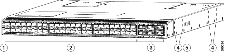
The following figure shows the switch features on the port side of the chassis.
|
1 |
Beacon (BCN), Status (STS), and Environment (ENV) LEDs |
4 |
Screw holes for mounting brackets |
|
2 |
10-Gigabit SFP+ downlink ports (48) supporting 1-, 10-, and 25-Gigabit Ethernet |
5 |
Grounding pad |
|
3 |
100-Gigabit QSFP28 uplink ports (6) supporting 40- and 100-Gigabit Ethernet |
To determine which transceivers, adapters, and cables are supported by this switch, see the Cisco Transceiver Modules Compatibility Information document.
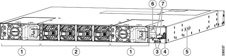
The following figure shows the switch features on the power supply side of the chassis.
|
1 |
Power supply modules (1 or 2) (AC power supplies shown) with slots numbered 1 (left) and 2 (right) |
5 |
Grounding pad |
|
2 |
Fan modules (4) with slots numbered from 1 (left) to 4 (right) |
6 |
Console port (1) |
|
3 |
Beacon (BCN) and Status (STS) LEDs |
7 |
Management ports (2—RJ-45 and SFP) |
|
4 |
USB port (1) |
Depending on whether you plan to position the ports in a hot or cold aisle, you can order the fan and power supply modules with port-side intake or port-side exhaust airflow. For port-side intake airflow, the fan and AC power supply modules have burgundy coloring (DC power supply modules have green coloring). For port-side exhaust airflow, the fan and AC power supplies have blue coloring (DC power supply modules have gray coloring). You can also order the 1200-W HVAC/HVDC power supply which has dual-direction airflow with white coloring. Dual-direction airflow modules automatically use the airflow direction of the other modules installed in the switch.
The fan and power supply modules are field replaceable and you can replace one fan module or one power supply module during operations so long as the other modules are installed and operating. If you have only one power supply installed, you can install the replacement power supply in the open slot before removing the original power supply.
Note |
All of the fan and power supply modules must have the same direction of airflow. Otherwise, the switch can overheat and shut down. If you are installing a dual-direction power supply, that module will automatically use the same airflow direction as the other modules in the switch. |
 Caution |
If the switch has port-side intake airflow (burgundy coloring for fan modules), you must locate the ports in the cold aisle. If the switch has port-side exhaust airflow (blue coloring for fan modules), you must locate the ports in the hot aisle. If you locate the air intake in a hot aisle, the switch can overheat and shut down. |
 Feedback