Cisco Nexus 1000V Installation and Upgrade Guide, Release 4.2(1)SV2(1.1a)
Bias-Free Language
The documentation set for this product strives to use bias-free language. For the purposes of this documentation set, bias-free is defined as language that does not imply discrimination based on age, disability, gender, racial identity, ethnic identity, sexual orientation, socioeconomic status, and intersectionality. Exceptions may be present in the documentation due to language that is hardcoded in the user interfaces of the product software, language used based on RFP documentation, or language that is used by a referenced third-party product. Learn more about how Cisco is using Inclusive Language.
Chapter: Installing the Cisco Nexus 1000V
- Information About Installing the Cisco Nexus 1000V
- Prerequisites for Installing the Cisco Nexus 1000V
- Guidelines and Limitations
- Installing a VSM HA Pair with L3 Mode Behind a VEM Using the Cisco Nexus 1000V Installer App
- Installing VSM Software Using the Cisco Nexus 1000V Installer App
- Installing Cisco Nexus 1000V in Standard Mode
- Installing the Cisco Nexus 1000V in Custom Mode
- Layer 2 on the Same Host
- Configuring Layer 2 Connectivity
- Installing the VEM Software Using the Cisco Nexus 1000V Installer App
- Adding VEM Hosts to the Distributed Virtual Switch
- Setting Virtual Machine Startup and Shutdown Parameters
- Installing the VEM Software Using VUM
- Installing the VEM Software Using the CLI
- Installing VEM Software Locally on a VMware 4.1 Host by Using the CLI
- Installing the VEM Software Remotely on a VMware 4.1 Host by Using the CLI
- Installing the VEM Software Locally on a VMware 5.0 Host by Using the CLI
- Installing VEM Software Remotely on a VMware 5.0 Host by Using the CLI
- Installing the VEM Software on a Stateless ESXi Host
- Installing a VSM on the Cisco Nexus 1010
- Feature History for Installing the Cisco Nexus 1000V
Installing the Cisco Nexus 1000V
This chapter contains the following sections:
Information About Installing the Cisco Nexus 1000V
VSM Software
You can obtain the Cisco Nexus 1000V software from the Cisco Nexus 1000V Series Switches web page:
Cisco Nexus 1000V Download Software page
The file name is Nexus1000v.4.2.1.SV2.1.1a.zip.
VEM Software
You can obtain the Virtual Ethernet Module (VEM) software from the sources listed in the following table:
Source |
Description |
|---|---|
VSM |
After the VSM has been installed as a Virtual Machine (VM), copy the file that contains the VEM software from the Virtual Supervisor Module (VSM) home page located at the following URL: http://VSM_IP_Address/ |
Cisco |
Download the VEM software from the Cisco Nexus 1000V Download Software page. |
Information About the Cisco Nexus 1000V Installer App
The Cisco Nexus 1000V Installer App is the graphical user interface (GUI) for installing the VSMs in high availability (HA) mode and the VEMs on ESX/ESXi hosts.
To prevent a disruption in connectivity, all port profiles are created with a system VLAN. You can change this after migration if needed.
The host and adapter migration process moves all physical network interface cards (PNICs) used by the VSM from the VMware vSwitch to the Cisco Nexus 1000V Distributed Virtual Switch (DVS).
The migration process supports Layer 2 and Layer 3 topologies.
The installer does the following:
- Creates port profiles for the control, management, and packet port groups.
- Creates uplink port profiles.
- Creates port profiles for VMware kernel NICs.
- Specifies a VLAN to be used for system login and configuration, and control and packet traffic.

NoteYou can use the same VLAN for control, packet, and management port groups, but you can also use separate VLANs for flexibility. If you use the same VLAN, make sure that the network segment where the VLAN resides has adequate bandwidth and latency.
- Enables Telnet and Secure Shell (SSH) and configures an SSH connection.
- Creates a Cisco Nexus 1000V plug-in and registers it on the vCenter Server.
- Migrates each VMware port group or kernel NIC to the correct port profile.
- Migrates each physical network interface card (PNIC) from the VMware vSwitch to the correct uplink on the DVS.
- Adds the host to the DVS.
- The Cisco Nexus 1000V Installer App provides a quick method for a user to deploy VSMs and VEMs with minimal or custom inputs on a single screen and expect a fully functional Cisco Nexus 1000V setup. See the following link for best practice recommendations in the deployment of Cisco Nexus 1000V: http://www.cisco.com/en/US/prod/collateral/switches/ps9441/ps9902/guide_c07-556626.html.
Prerequisites for Installing the Cisco Nexus 1000V
Cisco Nexus 1000V Installer App Prerequisites
Note | The Installation Management Center requires you to satisfy all the prerequisites. |
If you migrate the host and adapters from the VMware vSwitch to the Cisco Nexus 1000V DVS:
- The host must have one or more physical NICs on each VMware vSwitch in use.
- The VMware vSwitch must not have any active VMs. To prevent a disruption in connectivity during migration, any VMs that share a VMware vSwitch with port groups used by the VSM must be powered off.
- You must also configure the VSM connection to the vCenter server datacenter where the host resides.
- Host should have only one VMware vSwitch.
- Make sure no VEMs were previously installed on the host where the VSM resides.
- You must have administrative credentials for the vCenter Server.
- The java.exe file must be located within the search path defined in your system.
Host Prerequisites
The ESX or ESXi hosts to be used for the Cisco Nexus 1000V have the following prerequisites:
- You have already installed and prepared the vCenter Server for host management using the instructions from VMware.
- You should have the VMware vSphere Client installed.
- You have already installed the VMware Enterprise Plus license on the hosts.
- All VEM hosts must be running ESX/ESXi 4.1 or later releases.
- You have two physical NICs on each host for redundancy. Deployment is also possible with one physical NIC.
- If you are using a set of switches, make sure that the inter-switch trunk links carry all relevant VLANs, including control and packet VLANs. The uplink should be a trunk port that carries all VLANs configured on the host.
- The control and management VLANs must already be configured on the host to be used for the VSM VM.
- Make sure that the VM to be used for the VSM meets the minimum requirements listed in the following table.
- All the vmnics should have the same configuration upstream.
 Caution | The VSM VM might fail to boot if RAM and CPU are not properly allocated. This document includes procedures for allocating RAM and setting the CPU speed. |
The following table lists the minimum requirements for hosting a VSM.
VSM VM Component |
Minimum Requirement |
|---|---|
Platform |
64-bit |
Type |
Other 64-bit Linux (recommended) |
Processor |
1 |
RAM (configured and reserved) |
2 GB1 |
NIC |
3 |
SCSI Hard Disk |
3 GB with LSI Logic Parallel adapter |
CPU speed |
1500 MHz2 |
Upstream Switch Prerequisites
The switch upstream from the Cisco Nexus 1000V has the following prerequisites:
- If you are using a set of switches, make sure that the inter-switch trunk links carry all relevant VLANs, including the control and packet VLANs. The uplink must be a trunk port that carries all the VLANs that are configured on the host.
The following spanning tree prerequisites apply to the switch upstream from the Cisco Nexus 1000V on the ports connected to the VEM. For more information about spanning tree and its supporting commands, see the documentation for your upstream switch.- On upstream switches, the following configuration is mandatory: On your Catalyst series switches with Cisco IOS software, enter the following command: (config-if) spanning-tree portfast trunk or (config-if) spanning-tree portfast edge trunk On your Cisco Nexus 5000 series switches with Cisco NX-OS software, enter the following command: (config-if) spanning-tree port type edge trunk
- On upstream switches we highly recommend that you enable the following globally: Global BPDU Filtering Global BPDU Guard
- On upstream switches where you cannot globally enable BPDU Filtering and BPDU Guard, we highly recommend that you enter the following commands: (config-if) spanning-tree bpdu filter (config-if) spanning-tree bpdu guard
- Run the following commands on the upstream switch:
show running interface interface number
interface GigabitEthernet interface number
 description description of interface
switchport
switchport trunk encapsulation dot1q
switchport trunk native VLAN native VLAN
switchport trunk allowed vlan list of VLANs
switchport mode trunk

end
VSM Prerequisites
The Cisco Nexus 1000V VSM software has the following are prerequisites:
- You have the VSM IP address.
- You have installed the appropriate vCenter Server and VMware Update Manager (VUM) versions.
- If you are installing redundant VSMs, make sure that you first install and set up the software on the primary VSM before installing and setting up the software on the secondary VSM.
- You have already identified the HA role for this VSM from the list in the following table.
HA Role |
Single Supervisor System |
Dual Supervisor System |
|---|---|---|
Standalone (test environment only) |
X |
|
HA |
X |
Note | A standalone VSM is not supported in a production environment. |
- You are familiar with the Cisco Nexus 1000V topology diagram that is shown in Layer 3 Topology.
VEM Prerequisites
The Cisco Nexus 1000V VEM software has the following prerequisites:
Note | If the VMware vCenter Server is hosted on the same ESX/ESXi host as a Cisco Nexus 1000V VEM, a VUM-assisted upgrade on the host will fail. You should manually vMotion the vCenter Server VM to another host before you perform an upgrade. |
- When you perform any VUM operation on hosts that are a part of a cluster, ensure that VMware HA, VMware fault tolerance (FT), and VMware distributed power management (DPM) features are disabled for the entire cluster. Otherwise, VUM cannot install the hosts in the cluster.
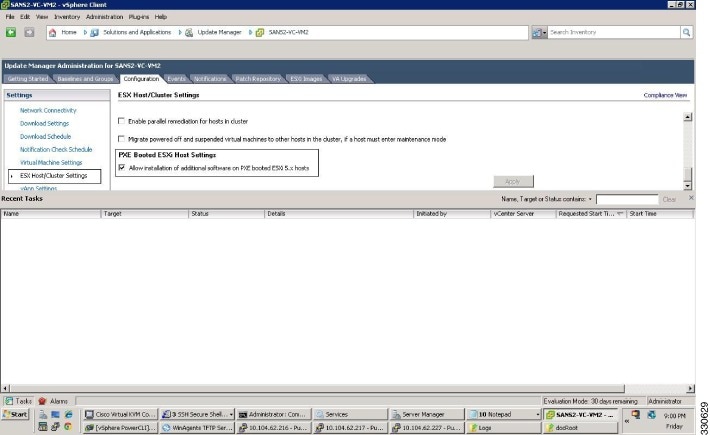
- If the hosts are in ESXi stateless mode, then enable the Pxe Booted ESXi host settings available under .
- You have a copy of your VMware documentation available for installing software on a host.
- You have already obtained a copy of the VEM software file from one of the sources listed in VEM Software.
- You have already downloaded the correct VEM software based on the current ESX/ESXi host patch level. For more information, see the Cisco Nexus 1000V and VMware Compatibility Information.
- For a VUM-based installation, you must deploy VUM and make sure that the VSM is connected to the vCenter Server.
Guidelines and Limitations
Guidelines and Limitations of the Cisco Nexus 1000V Installer App
Configuring the software using the Cisco Nexus 1000V Installer App has the following guidelines and limitations:
- For a complete list of port profile guidelines and limitations, see the Cisco Nexus 1000V Port Profile Configuration Guide.
CautionHost management connectivity might be interrupted if the management vmknic or vswif are migrated and the uplink’s native VLAN is not correctly specified in the setup process.
- If you are installing a Cisco Nexus 1000V in an environment where the upstream switch does not support static port channels, such as the Cisco Unified Computing System (UCS), you must use the channel-group auto mode on the mac-pinning command instead of the channel-group auto mode command.
- We recommend that you install redundant VSMs on the Cisco Nexus 1000V. For information about high availability and redundancy, see the Cisco Nexus 1000V High Availability and Redundancy Configuration Guide.
- For a user using the VC Connection installer, once the SVS connection is completed, the user must check the VSM using the show svs connection command to view an accurate status.
- Layer 3 mode of deployment is supported by the Cisco Nexus 1000V Installer App with ESXi host only.
- VEM installation and migration are supported for a maximum of four vmknics in a single subnet per host to deploy 64 VEMs. No more than four vmknics can be present on a single host during VEM installations.
- The Cisco Nexus 1000V Installer App can support 14 different subnets during module additions when reusing port profiles.
- The Cisco Nexus 1000V Installer App will always deploy with VSM HA pairs.
Guidelines and Limitations for Installing the Cisco Nexus 1000V
Use the following guidelines and limitations when installing the Cisco Nexus 1000V software:
- Do not enable VMware FT for the VSM VM because it is not supported. Instead, Cisco NX-OS HA provides high availability for the VSM.
- The VSM VM supports VMware HA. However, we strongly recommend that you deploy redundant VSMs and configure Cisco NX-OS HA between them. Use the VMware recommendations for the VMware HA.
- Do not enable VM Monitoring for the VSM VM because it is not supported, even if you enable the VMware HA on the underlying host. Cisco NX-OS redundancy is the preferred method.
-
When you move a
VSM from the VMware vSwitch to the
Cisco Nexus 1000V DVS, it is possible that the
connectivity between the active and standby VSM is temporarily lost. In that
situation, both active and standby VSMs assume the active role.
The reboot of the VSM is based on the following conditions: - If the VSM is moved from the VMware vSwitch to the Cisco Nexus 1000V DVS, it is recommended that you configure the port-security on the VSM vethernet interfaces to secure control/packet MACs.
- To improve redundancy, install primary and secondary VSM VMs on separate hosts that are connected to different upstream switches.
-
The Cisco Nexus 1000V VSM always uses the following three network interfaces in the same order as specified below: - There is no dependency on the VM hardware version, so the VM hardware version can be upgraded if required.
Installing a VSM HA Pair with L3 Mode Behind a VEM Using the Cisco Nexus 1000V Installer App
The procedure to install a VSM HA pair behind a VEM is as follows:
Installing VSM Software Using the Cisco Nexus 1000V Installer App
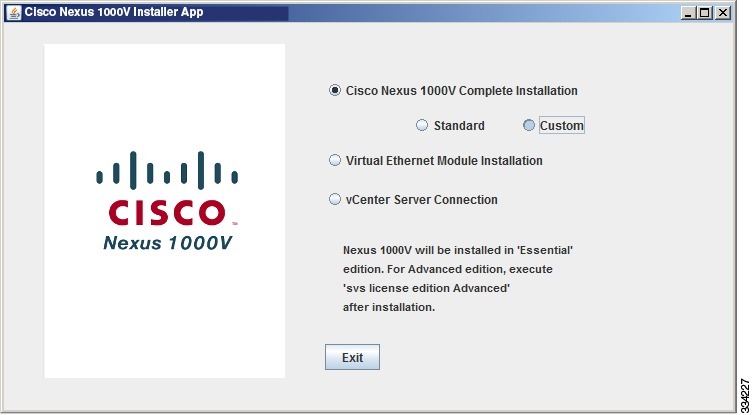
There are two procedures for installing the Cisco Nexus 1000V VSMs. The standard procedure is for the novice administrator. The custom procedure is for the more experienced administrator. The custom procedure has more configuration inputs to be used by administrators already familiar with the installation process and requiring more installation options.
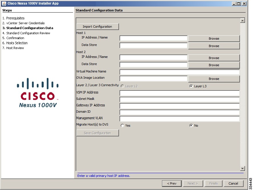
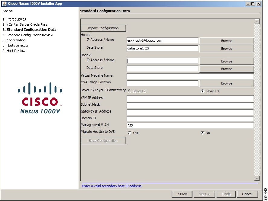
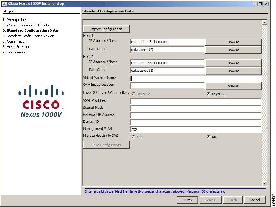
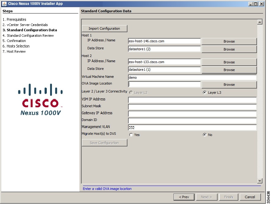
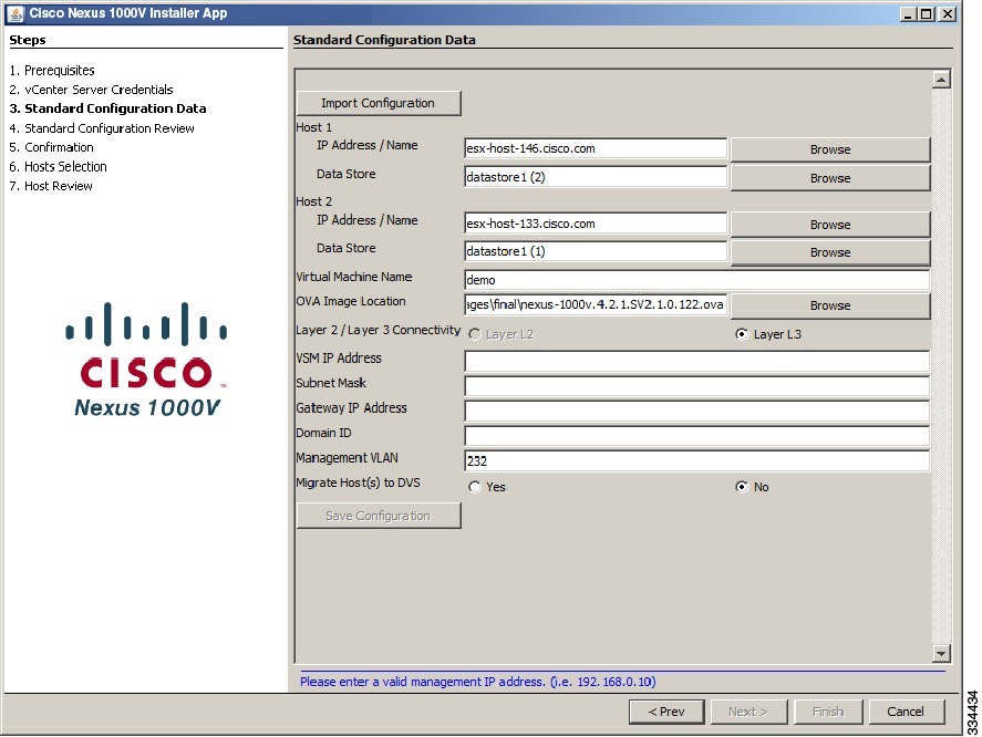
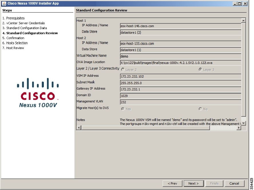
Installing Cisco Nexus 1000V in Standard Mode
You have the following information:
NoteThe VSM IP address must be in the same management VLAN as the host.
- You have the JDK version 1.6 or later installed on the host running the Cisco Nexus 1000V Installer App.
The VSM will be deployed with the following credentials: - If the user selects the migration to DVS option as yes, then the migration of hosts that have VSMs will migrate all the interfaces under the vSwitch that have the ESXi management interface (say vmk0 ).

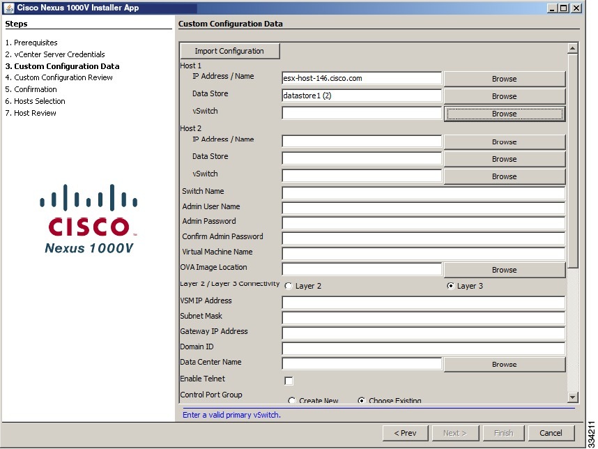
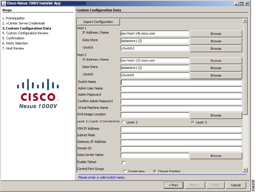
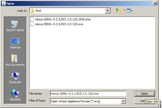
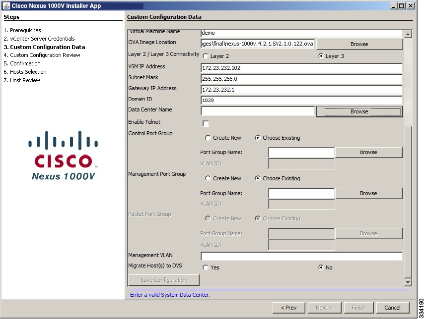
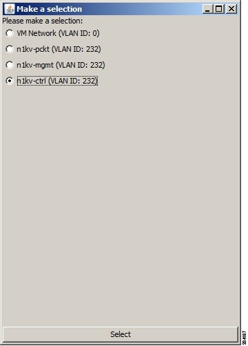
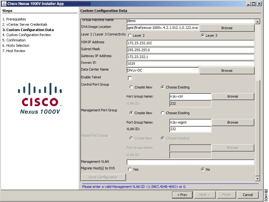
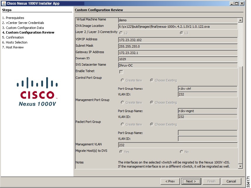
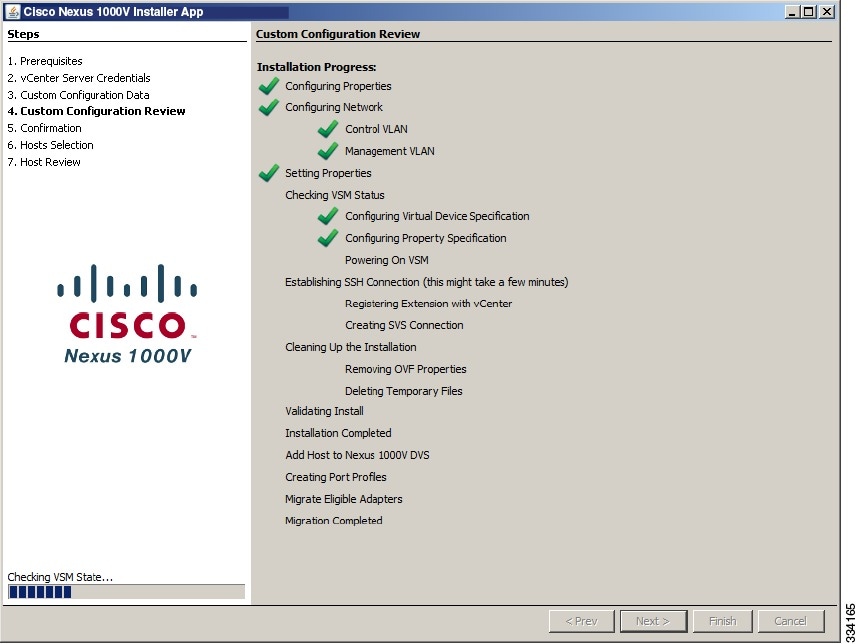
Installing the Cisco Nexus 1000V in Custom Mode
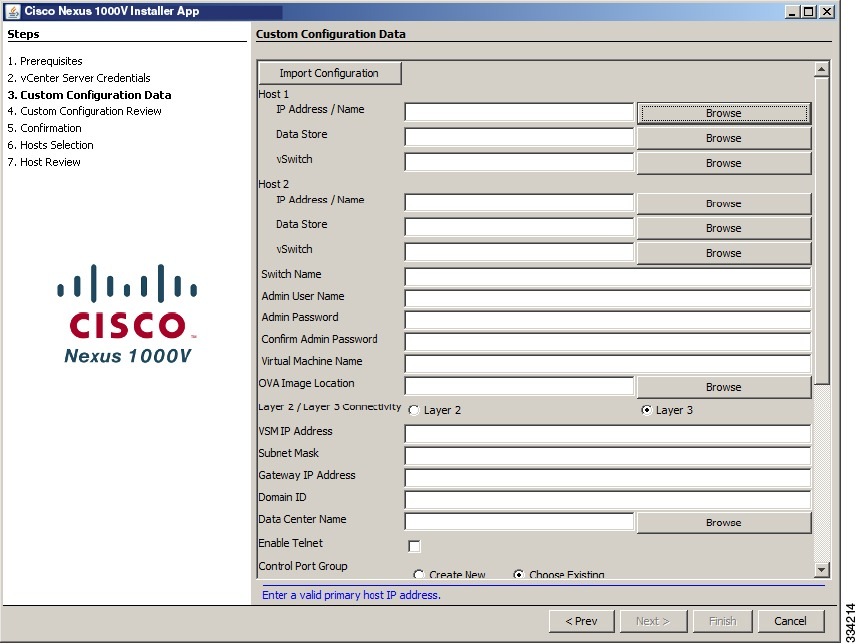


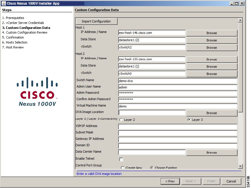
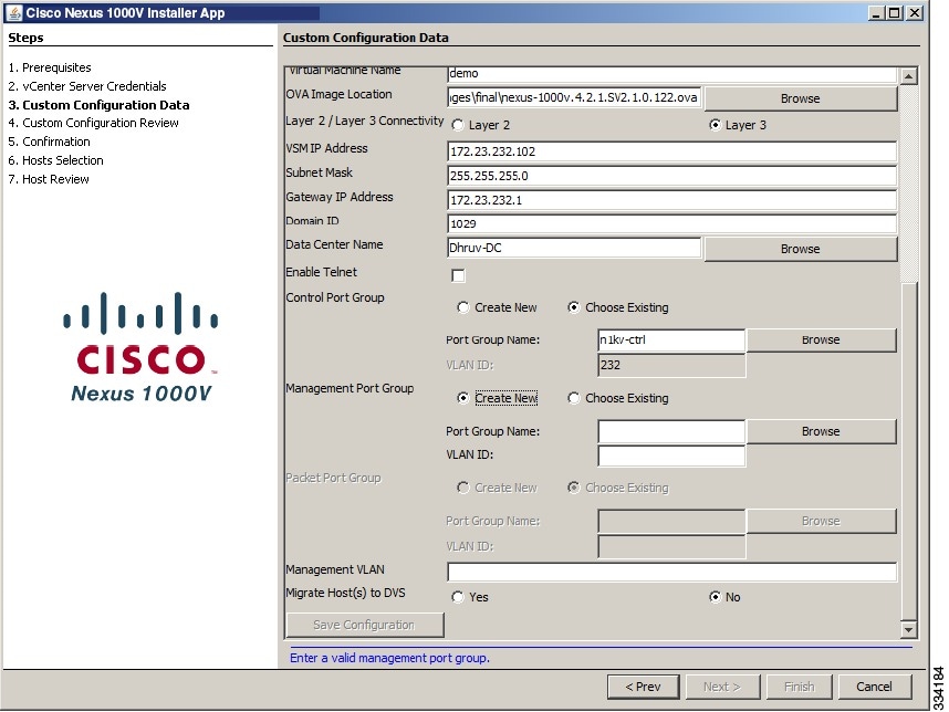
Information About Layer 2 Connectivity
Note | Layer 3 connectivity is the preferred method for communications between the VSM and the VEMs. |
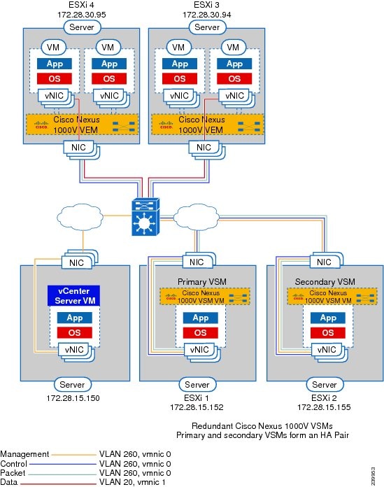
The following figure shows an example of redundant VSM VMs, where the software for the primary VSM is installed on ESXi 1, and the software for the secondary VSM is installed on ESXi 2 for Layer 2 connectivity.
Layer 2 on the Same Host
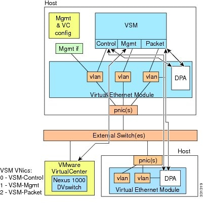
The following figure shows a VSM and VEM running on the same host in Layer 2 mode.
Configuring Layer 2 Connectivity
Note | Layer 3 connectivity is the preferred method. |
| Step 1 | To configure a different VMware vSwitch port group for each VSM network adapter, in the Configure Networking screen click L2: Configure port groups for L2. | ||
| Step 2 | In the Configure Networking screen, do the following:
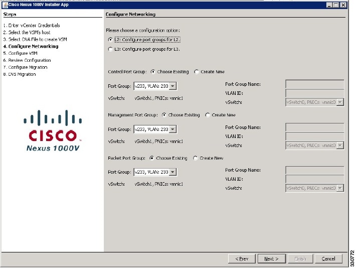 | ||
| Step 3 | Return to Step 17 in the Layer 2 configuration procedure. |
Installing the VEM Software Using the Cisco Nexus 1000V Installer App
- When the Cisco Nexus 1000V Installer App installs VEMs, it migrates all VEM kernels and their corresponding vmnics across vSwitches to the Nexus 1000V VEMs
- If a particular VEM is capable of hosting VSMs, the network administrator must manually allow control VLAN in the uplink port profile of VEMs in Layer 3 deployment mode for VSM HA communication.
Note | The hosts that will be installed as VEMs should not have any Cisco Nexus 1000V VIB files. Uninstall any Cisco Nexus 1000V VIBs before starting the Cisco Nexus 1000V Installer App. |
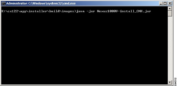
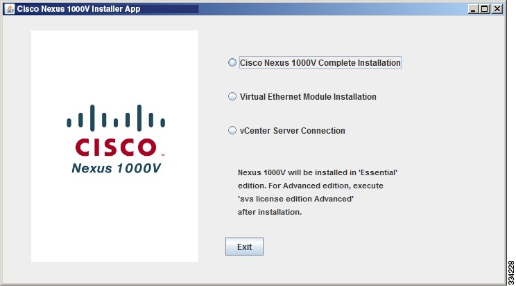
| Step 1 | Double-click on the installation application icon. Or, at the command-line interface, enter the following command to start the Cisco Nexus 1000V Installer App. java -jar Nexus1000V-install_CNX.jar | ||
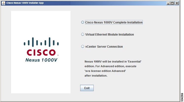
| Step 2 | Click the Virtual Ethernet Module Installation radio button. 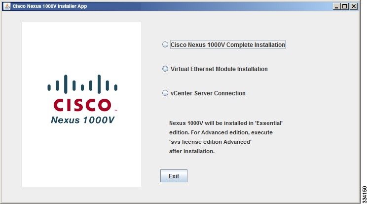 | ||
| Step 3 | After reading the Prerequisites, click Next. | ||
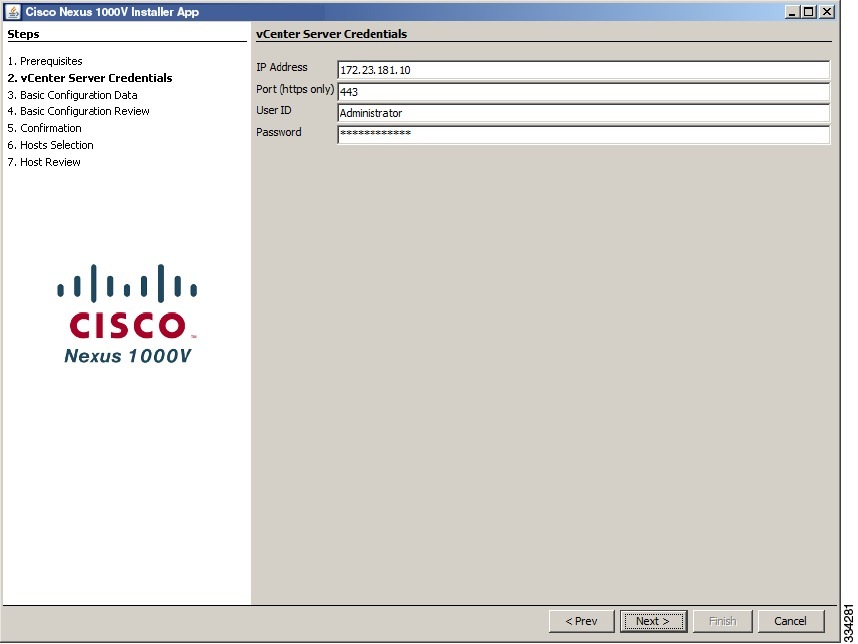
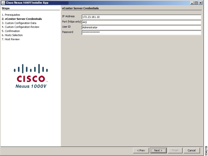
| Step 4 | In the VEM Enter vCenter Credentials screen, do the following: | ||
| Step 5 | In the VEM Enter VSM IP & Credentials screen, do the following: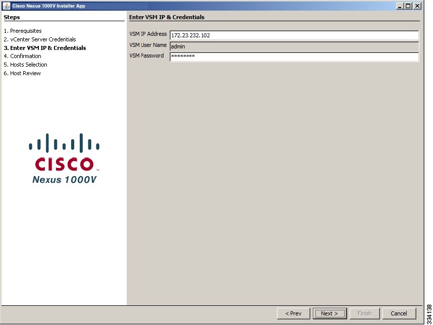 | ||
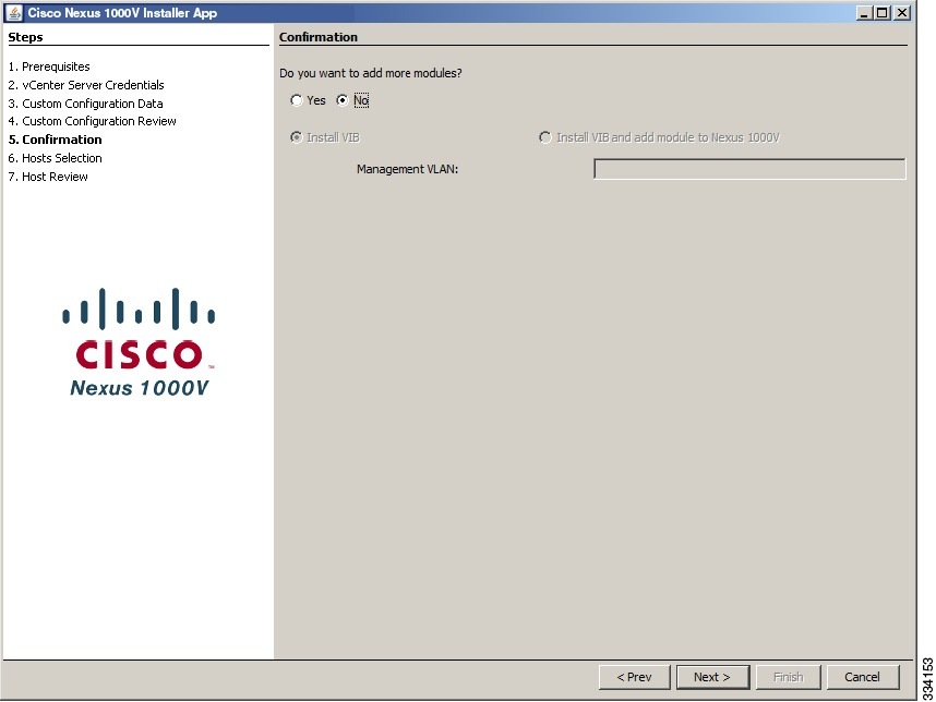
| Step 6 | In the Confirmation screen, do one of the following: | ||
| Step 7 | In the Adding Modules screen, do the following: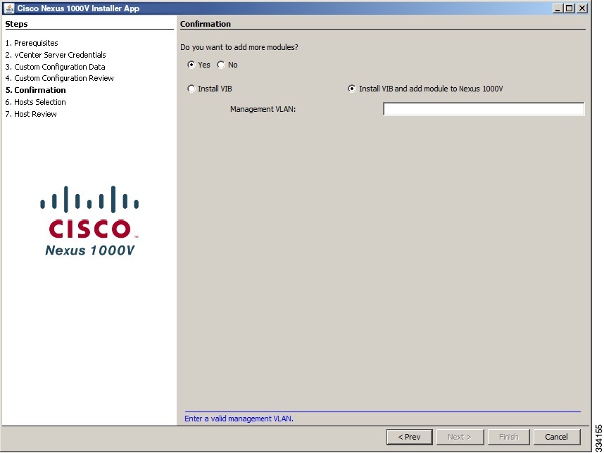 | ||
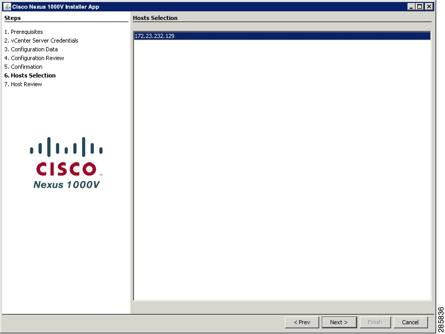
| Step 8 | In the VEM Hosts Selection screen, do the following:
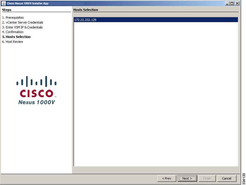 | ||
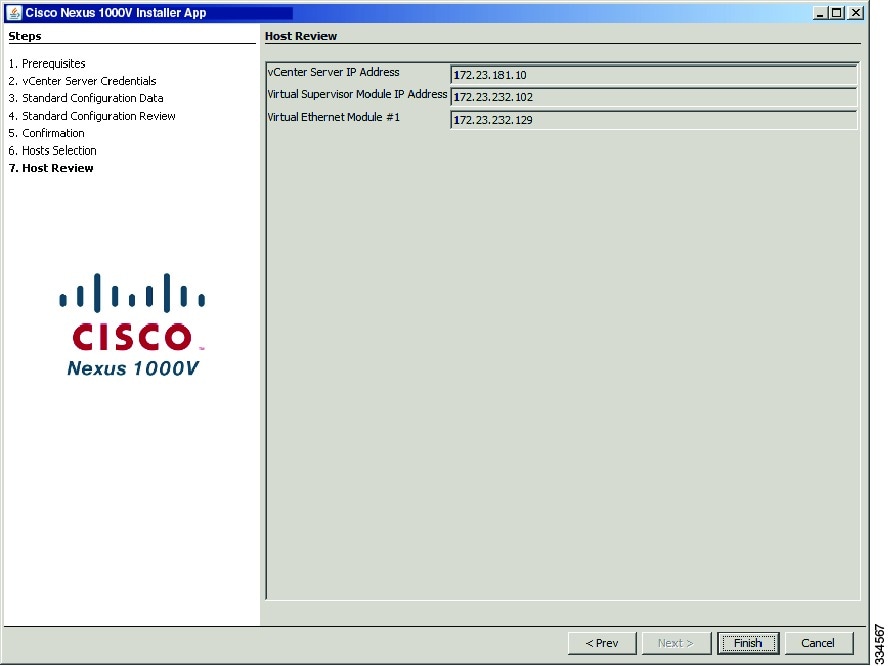
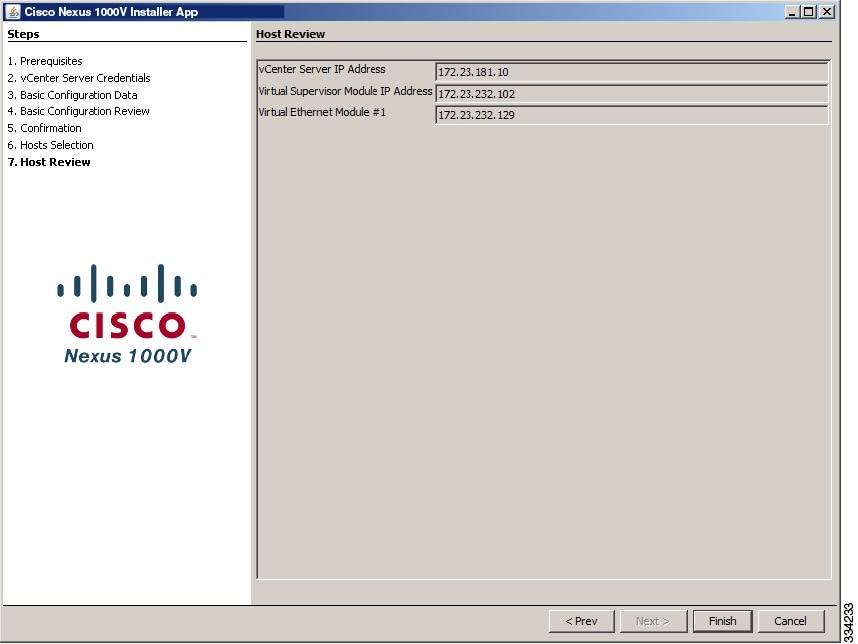
| Step 9 | In the VEM Host Review screen, do the following:
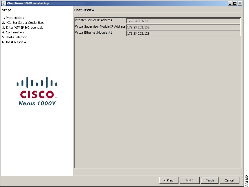 | ||
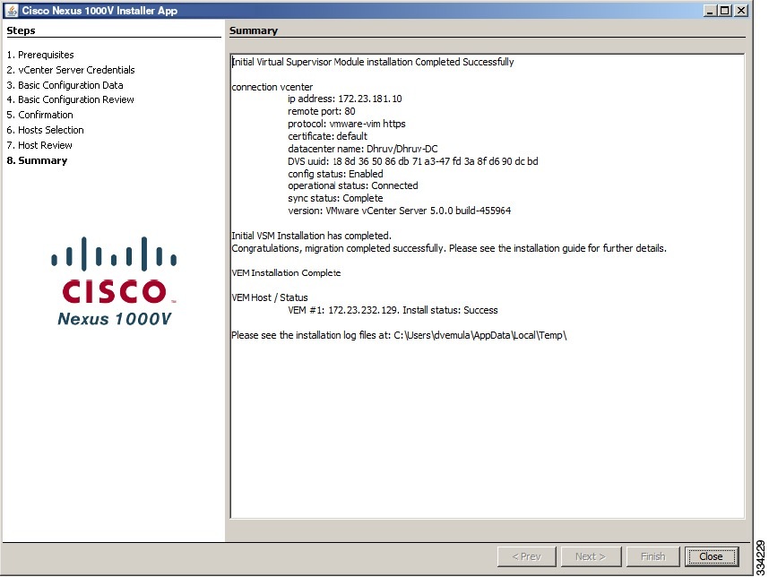
| Step 10 | In the VEM Summary screen, click Close. 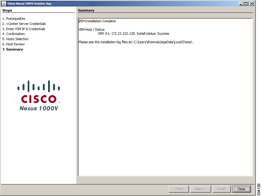
For more information about troubleshooting VSMs and VEMs, see the Cisco Nexus 1000V Troubleshooting Guide. |
Adding VEM Hosts to the Distributed Virtual Switch
| Step 1 |
In the vSphere Client window, choose Hosts and Clusters > Networking.
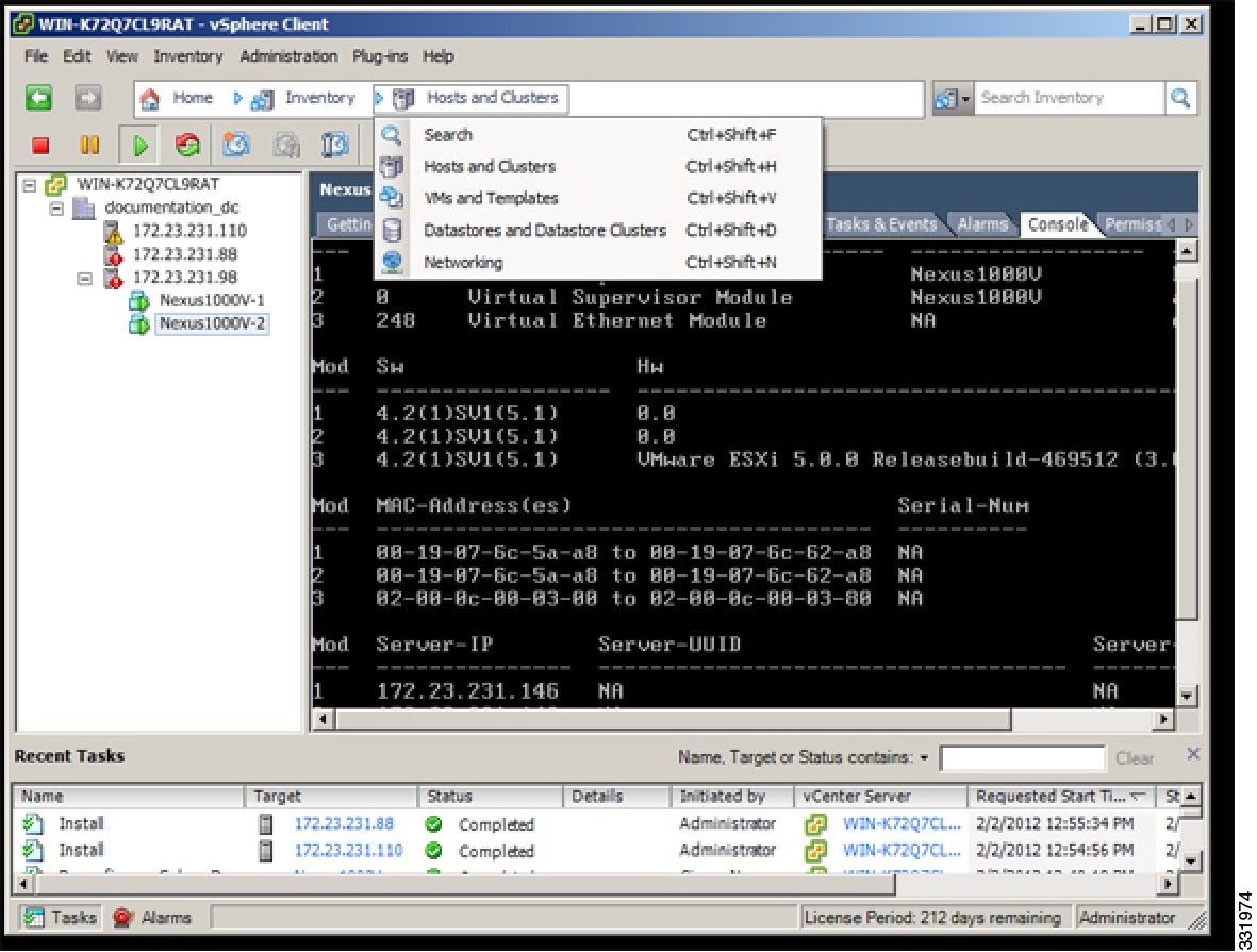 | ||
| Step 2 | In the vSphere Client Hosts window, choose the DVS and click the Hosts tab. 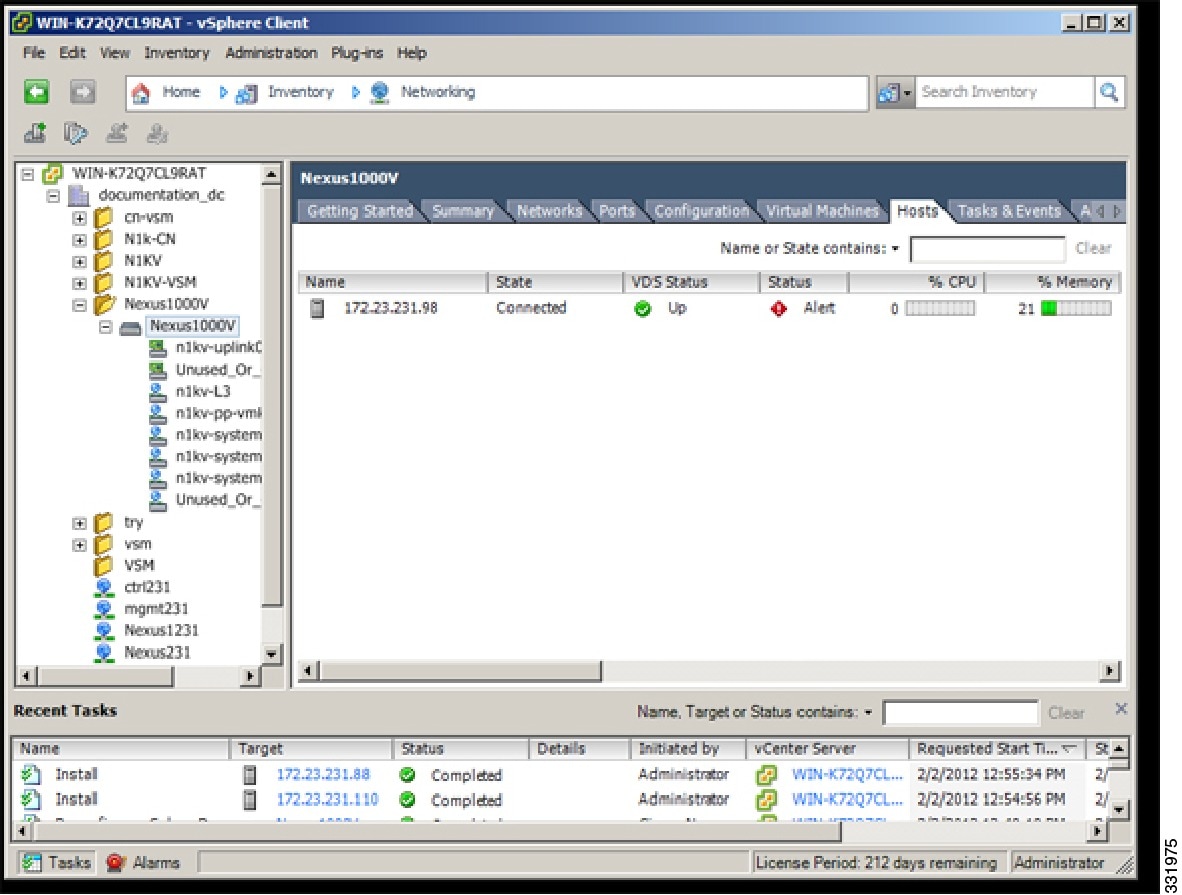 | ||
| Step 3 | In the Add Hosts to DVS window, right-click the DVS and from the drop-down list, choose Add Host. 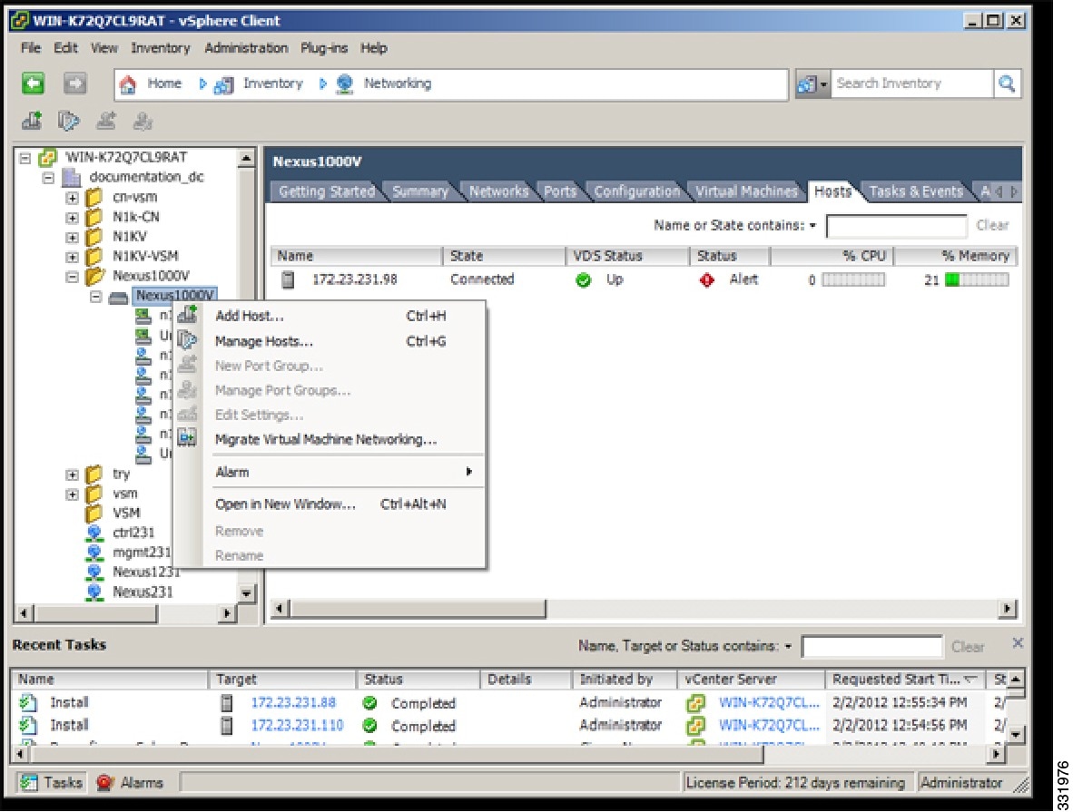 | ||
| Step 4 | In the Select Hosts and Physical Adapters screen, choose the hosts and the uplink port groups, and click Next. | ||
| Step 5 | In the Network Connectivity screen, click Next.
| ||
| Step 6 | In the Virtual Machine Networking screen, click Next. | ||
| Step 7 | In the Ready to Complete screen, click Finish. | ||
| Step 8 | In the vSphere Client Hosts window, confirm that the hosts are in the Connected state. |
The host connection process is complete.
Setting Virtual Machine Startup and Shutdown Parameters
| Step 1 |
In the vSphere Client window, choose a host and click the Configuration tab.
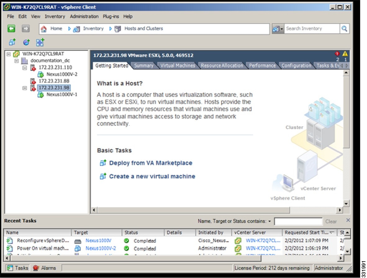 |
| Step 2 | In the Configuration pane, choose Virtual Machine Startup/Shutdown. 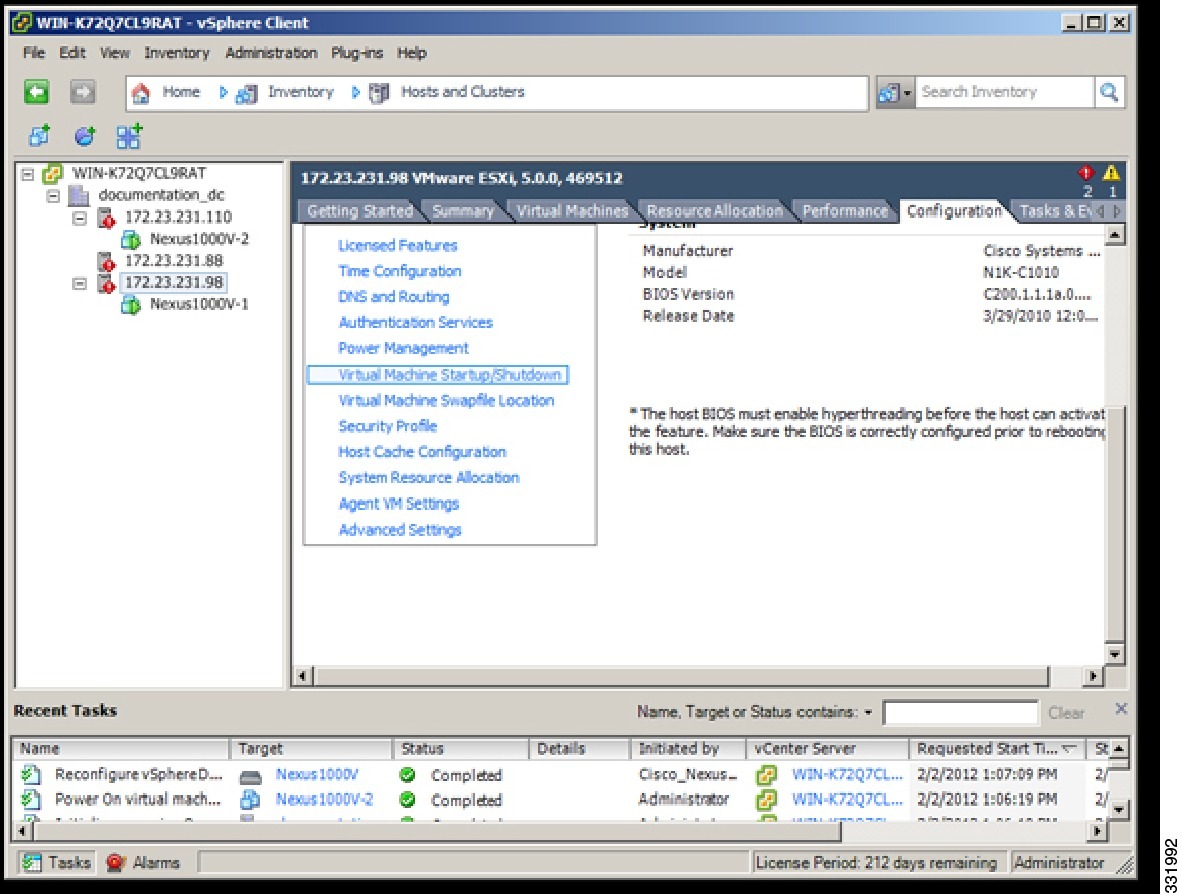 |
| Step 3 | In the Virtual Machine Startup and Shutdown pane, click the Properties link. 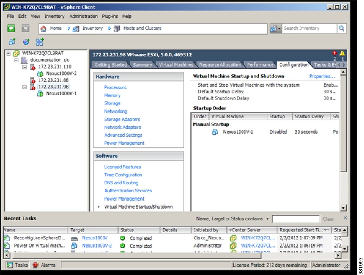 |
| Step 4 | In the System Settings dialog box, do the following: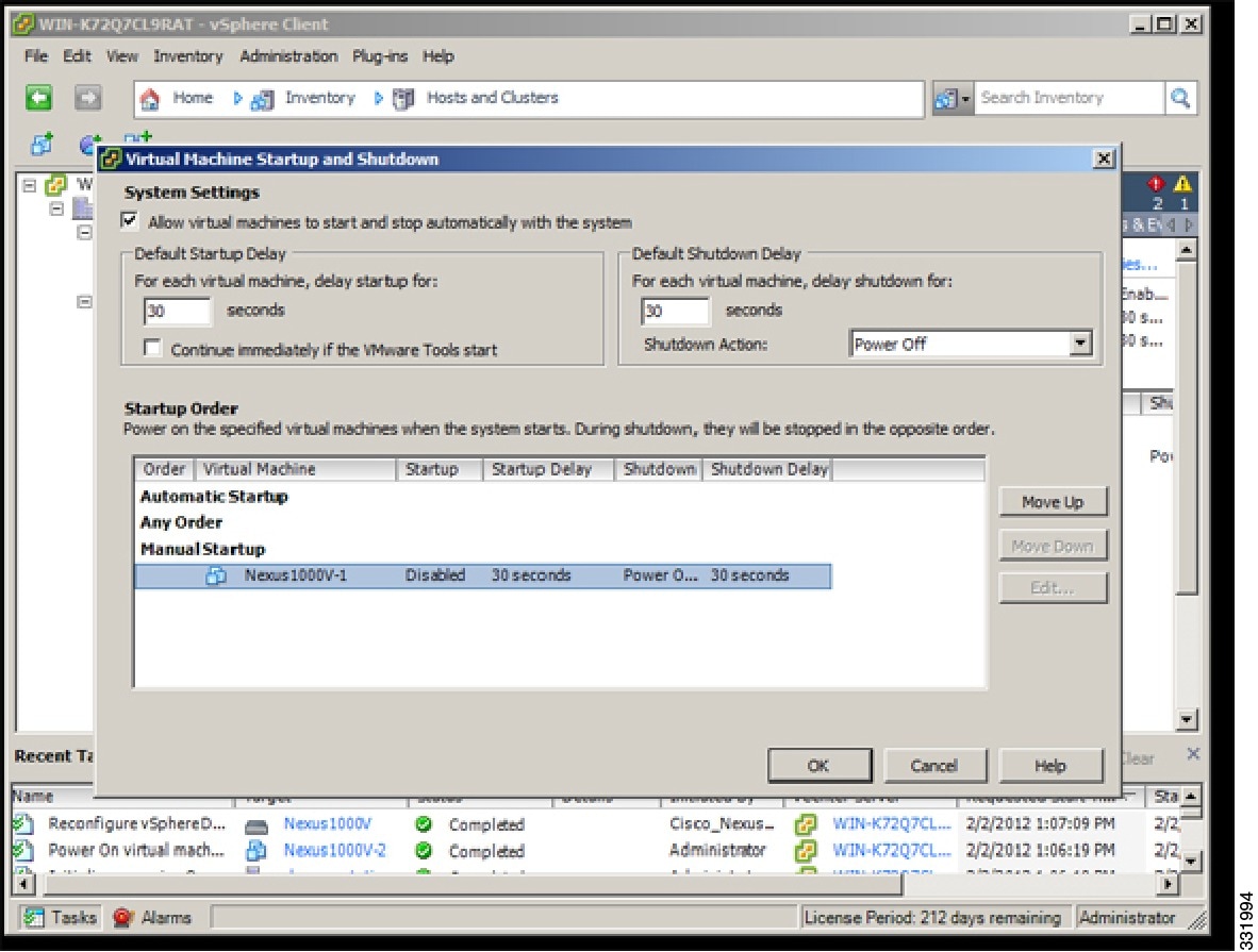 |
Startup and shutdown settings are complete.
Installing the VEM Software Using VUM
VMware Update Manager (VUM) automatically selects the correct VEM software to be installed on the host when the host is added to the DVS.
Note | Make sure that you read the VEM Prerequisites to ensure that the VUM operation proceeds without failure. |
Installing the VEM Software Using the CLI
There are four different installation paths based on the version of VMware ESX/ESXi software that is running on the server:
Installing VEM Software Locally on a VMware 4.1 Host by Using the CLI
- If you are using the esxupdate command, you are logged into the ESX host.
- Check the Cisco Nexus 1000V and VMware Compatibility Information for compatible versions.
- You have already copied the VEM software installation file to the /tmp directory.
- You know the name of the VEM software file to be installed.
| Step 1 |
From the ESX host /tmp directory, begin the VEM update procedure.
Example: /tmp # esxupdate --bundle VEM410-201301152101.zip update Unpacking cross_cisco-vem-v14.. ######################################## [100%] Installing packages :cross_ci.. ######################################## [100%] Running [/usr/sbin/vmkmod-install.sh]... ok. Example: /tmp # esxupdate -b cross_cisco-vem-v152-esx_4.2.1.2.1.1a.0-2.0.2.vib update Unpacking cross_cisco-vem-v140-esx.. ################################################# [100%] Installing packages :cross_cisco-v.. ################################################# [100%] Running [/usr/sbin/vmkmod-install.sh]... ok. This command loads the software manually onto the host, loads the kernel modules, and starts the VEM Agent on the running system. |
| Step 2 | Verify that the VEM software is installed on the host. /tmp # esxupdate --vib-view query | grep cisco cross_cisco-vem-v152-esx_4.2.1.2.1.1a.0-2.0.1.vib installed 2012-12-3T11:53:48.895694+00:00 |
| Step 3 | Verify that the installation was successful by checking for the “VEM Agent (vemdpa) is running” statement in the output of the vem status command. /tmp # vem status -v Package vssnet-esx5.5.0-00000-release Version 4.2.1.2.1.1a.0-2.0.2 Build 2 Date Tue Jan 31 05:01:37 PST 2012 Number of PassThru NICs are 0 VEM modules are loaded Switch Name Num Ports Used Ports Configured Ports MTU Uplinks vSwitch0 128 3 128 1500 vmnic0 Number of PassThru NICs are 0 VEM Agent (vemdpa) is running |
| Step 4 | Do one of the following: |
Installing the VEM Software Remotely on a VMware 4.1 Host by Using the CLI
Note | The vCLI command set allows you to enter common system administration commands against ESX/ESXi systems from any machine with network access to those systems. You can also enter most CLI commands against a vCenter Server system and target any ESX/ESXi system that the vCenter Server system manages. vCLI commands are especially useful for ESXi hosts because ESXi does not include a service console. |
| Step 1 | Go to the directory where the new VEM software was copied. [root@serialport -]# cd tmp [root@serialport tmp]# |
| Step 2 | Install the VEM software. [root@serialport tmp]# vihostupdate -i -b ./Cisco_updated_VEM_offline_bundle --server vsphere_host Example: [root@serialport tmp]# vihostupdate -i -b ./ VEM410-201301152101.zip --server 192.0.2.0 Enter username: root Enter password: Please wait patch installation is in progress ... Host updated successfully. |
| Step 3 | Verify that the VEM software is installed on the host. vihostupdate.pl -q --server host_ip_address Example: [root@serialport tmp]# vihostupdate.pl -q --server 192.0.2.1 Enter username: root Enter password: Look for the following: ---------Bulletin ID--------- -----Installed----- ----------------Summary------- ---------- VEM410-201301152101-BG 2012-02-02T00:54:14 Cisco Nexus 1000V 4.2(1)SV1(5.2) |
| Step 4 | Do one of the following: |
Installing the VEM Software Locally on a VMware 5.0 Host by Using the CLI
| Step 1 | Copy the VEM software to the /tmp directory. |
| Step 2 | Begin the VEM installation procedure. esxcli software vib install -v /tmp/VIB_FILE Example: ~ # esxcli software vib install -v /tmp/cross_cisco-vem-v152-4.2.1.2.1.1a.0-3.0.1.vib Installation Result Message: Operation finished successfully. Reboot Required: false VIBs Installed: Cisco_bootbank_cisco-vem- v152-esx_4.2.1.2.1.1a.0-3.0.1. VIBs Removed: VIBs Skipped: |
| Step 3 | Verify that the VEM software is installed on the host. ~ # esxcli software vib list | grep cisco cisco-vem-v152-esx 4.2.1.2.1.1a.0-3.0.1 Cisco PartnerSupported 2012-12-13 |
| Step 4 | Verify that the installation was successful by checking for the “VEM Agent (vemdpa) is running” statement in the output of the vem status command. Example: ~ # vem status -v Package vssnet-esxmn-ga-release Version 4.2.1.2.1.1a.0-3.0.1 Build 1 Date Mon Jan 30 18:38:49 PST 2012 Number of PassThru NICs are 0 VEM modules are loaded Switch Name Num Ports Used Ports Configured Ports MTU Uplinks vSwitch0 128 3 128 1500 vmnic0 Number of PassThru NICs are 0 VEM Agent (vemdpa) is running |
| Step 5 | Do one of the following: |
Installing VEM Software Remotely on a VMware 5.0 Host by Using the CLI
| Step 1 | Copy the VEM software to the NFS storage which is mounted on the ESXi 5.0 host. | ||
| Step 2 | Enter the following command from the remote machine where the vCLI is installed. esxcli --server=[server ip] software vib install --depot=Path_to_the_NFS_storage_mounted_ _on_ESXi_5.0 host Example: vi-admin@localhost:~> esxcli --server=192.0.2.2 software vib install --depot=/vmfs/volumes/newnfs/MN-patch01/CN-FCS/VEM500-201301152108-BG-release.zip Enter username: root Enter password: Installation Result Message: Operation finished successfully. Reboot Required: false VIBs Installed: Cisco_bootbank_cisco-vem-v152-esx_4.2.1.2.1.1a.0-3.0.2 VIBs Removed: VIBs Skipped: where 192.0.2.2 is the target ESXi 5.0 host IP address and newnfs is the NFS storage mounted on the ESXi 5.0 host.
| ||
| Step 3 | Verify that the VEM software is installed on the host. esxcli --server=host_ip_address software vib list Example: vi-admin@localhost:~> esxcli --server=192.0.2.1 software vib list Enter username: root Enter password: Look for the following: Name Version Vendor Acceptance Lev el Install Date -------------------- ---------------------------------- ------ -------------- -- ------------ cisco-vem-v152-esx 4.2.1.2.1.1a.0-3.0.2 Cisco PartnerSupport ed 2012-04-06 | ||
| Step 4 | Do one of the following: |
Installing the VEM Software on a Stateless ESXi Host
The following list outlines the VEM installation process on a stateless ESXi host.
| Step 1 | See the procedure for Adding the Cisco Nexus 1000V to an ESXi Image Profile. |
| Step 2 | Installing the VEM software using one of the two following procedures: |
| Step 3 | See the procedure for Configuring Layer 2 Connectivity. |
Stateless ESXi Host
Note | For Stateless ESXi, the VLAN used for Preboot Execution Environment (gPXE) and Management must be a native VLAN in the Cisco Nexus 1000V management uplink. It must also be a system VLAN on the management VMkernel NIC and on the uplink. |
VMware vSphere 5.0.0 introduces the VMware Auto Deploy, which provides the infrastructure for loading the ESXi image directly into the host’s memory. The software image of a stateless ESXi is loaded from the Auto Deploy Server after every boot. In this context, the image with which the host boots is identified as the image profile.
An image profile is a collection of vSphere Installation Bundles (VIBs) required for the host to operate and the image profile includes base VIBs from VMware and additional VIBs from partners.
On a stateless host, VEM software can be installed or upgraded using either the VUM or CLI.
In addition, you should bundle the new or modified VEM module in the image profile from which the stateless host boots. If it is not bundled in the image profile, the VEM module does not persist across reboots of the stateless host.
For more information about the VMware Auto Deploy Infrastructure and stateless boot process, see the “Installing ESXi using VMware Auto Deploy” chapter of the vSphere Installation and Setup, vSphere 5.0.0 document.
Adding the Cisco Nexus 1000V to an ESXi Image Profile
- Install and set up the VMware Auto Deploy Server. See the vSphere Installation and Setup document.
- Install the VMware PowerCLI on a Windows platform. This step is required for bundling the VEM module into the image profile. For more information, see the vSphere PowerCLI Installation Guide.
- On the same Windows platform, where VMware PowerCLI is installed, do the following:
Note | In the following procedure, the image profile bundle is available as C:\ESXi-5.0.0-depot.zip and the VEM bundle is available as C:\VEM500-201301152108-BG.zip. |
| Step 1 | Start the vSphere PowerCLI application. | ||||
| Step 2 | Connect to the vCenter Server. [vSphere PowerCLI] > Connect-VIServer 192.0.2.1 –User Administrator –Password XXXXX | ||||
| Step 3 | Load the image profile offline bundle.
[vSphere PowerCLI] > Add-ESXSoftwareDepot c:\vmware-ESXi-5.0.0-depot.zip | ||||
| Step 4 | List the image profiles. [vSphere PowerCLI] > Get-EsxImageProfile Name Vendor Last Modified ---- ------ ------------- ESXi-5.0.0-standard VMware, Inc. 2/25/2011 9:42:21 PM ESXi-5.0.0-no-tools VMware, Inc. 2/25/2011 9:42:21 PM | ||||
| Step 5 | Choose the image profile into which the VEM is to be bundled from the output of the Get-EsxImageProfile command.
[vSphere PowerCLI] > New-EsxImageProfile -CloneProfile ESXi-5.0.0-standard -Name n1kv-Image
| ||||
| Step 6 | Load the Cisco Nexus 1000V VEM offline bundle.
[vSphere PowerCLI] > Add-EsxSoftwareDepot C:\VEM500-20110822140-BG.zip | ||||
| Step 7 | Confirm that the n1kv-vib package is loaded. [vSphere PowerCLI] > Get-EsxSoftwarePackage -Name cisco* Name Version Vendor Release ---- ------- ------ ----------- cisco-vem-v152-esx 4.2.1.2.1.1a.0-3.0.1 Cisco 8/22/2011. | ||||
| Step 8 | Bundle the n1kv-package into the cloned image profile. [vSphere PowerCLI] > Add-EsxSoftwarePackage -ImageProfile n1kv-Image -SoftwarePackage cisco-vem-v131-esx | ||||
| Step 9 | List all the VIBs in the cloned image profile. [vSphere PowerCLI]> $img = Get-EsxImageProfile n1kv-Image [vSphere PowerCLI]> $img.vibList Name Version Vendor Release Date ---- ------- ------ ------------ scsi-bnx2i 1.9.1d.v50.1-3vmw.500.0.0.4... VMware 6/22/2011... net-s2io 2.1.4.13427-3vmw.500.0.0.43... VMware 6/22/2011... net-nx-nic 4.0.557-3vmw.500.0.0.434219 VMware 6/22/2011... scsi-aic79xx 3.1-5vmw.500.0.0.434219 VMware 6/22/2011... sata-ata-piix 2.12-4vmw.500.0.0.434219 VMware 6/22/2011... net-e1000e 1.1.2-3vmw.500.0.0.434219 VMware 6/22/2011... net-forcedeth 0.61-2vmw.500.0.0.434219 VMware 6/22/2011... tools-light 5.0.0-0.0.434219 VMware 6/22/2011... ipmi-ipmi-msghandler 39.1-4vmw.500.0.0.434219 VMware 6/22/2011... scsi-aacraid 1.1.5.1-9vmw.500.0.0.434219 VMware 6/22/2011... net-be2net 4.0.88.0-1vmw.500.0.0.434219 VMware 6/22/2011... sata-ahci 3.0-6vmw.500.0.0.434219 VMware 6/22/2011... ima-qla4xxx 2.01.07-1vmw.500.0.0.434219 VMware 6/22/2011... ata-pata-sil680 0.4.8-3vmw.500.0.0.434219 VMware 6/22/2011... scsi-ips 7.12.05-4vmw.500.0.0.434219 VMware 6/22/2011... scsi-megaraid-sas 4.32-1vmw.500.0.0.434219 VMware 6/22/2011... scsi-mpt2sas 06.00.00.00-5vmw.500.0.0.43... VMware 6/22/2011... net-cnic 1.10.2j.v50.7-2vmw.500.0.0.... VMware 6/22/2011... ipmi-ipmi-si-drv 39.1-4vmw.500.0.0.434219 VMware 6/22/2011... esx-base 5.0.0-0.0.434219 VMware 6/22/2011... ata-pata-serverworks 0.4.3-3vmw.500.0.0.434219 VMware 6/22/2011... scsi-mptspi 4.23.01.00-5vmw.500.0.0.434219 VMware 6/22/2011... net-bnx2x 1.61.15.v50.1-1vmw.500.0.0.... VMware 6/22/2011... ata-pata-hpt3x2n 0.3.4-3vmw.500.0.0.434219 VMware 6/22/2011... sata-sata-sil 2.3-3vmw.500.0.0.434219 VMware 6/22/2011... scsi-hpsa 5.0.0-17vmw.500.0.0.434219 VMware 6/22/2011... block-cciss 3.6.14-10vmw.500.0.0.434219 VMware 6/22/2011... net-tg3 3.110h.v50.4-4vmw.500.0.0.4... VMware 6/22/2011... net-igb 2.1.11.1-3vmw.500.0.0.434219 VMware 6/22/2011... ata-pata-amd 0.3.10-3vmw.500.0.0.434219 VMware 6/22/2011... ata-pata-via 0.3.3-2vmw.500.0.0.434219 VMware 6/22/2011... net-e1000 8.0.3.1-2vmw.500.0.0.434219 VMware 6/22/2011... scsi-adp94xx 1.0.8.12-6vmw.500.0.0.434219 VMware 6/22/2011... scsi-lpfc820 8.2.2.1-18vmw.500.0.0.434219 VMware 6/22/2011... scsi-mptsas 4.23.01.00-5vmw.500.0.0.434219 VMware 6/22/2011... ata-pata-cmd64x 0.2.5-3vmw.500.0.0.434219 VMware 6/22/2011... sata-sata-svw 2.3-3vmw.500.0.0.434219 VMware 6/22/2011... misc-cnic-register 1.1-1vmw.500.0.0.434219 VMware 6/22/2011... ipmi-ipmi-devintf 39.1-4vmw.500.0.0.434219 VMware 6/22/2011... sata-sata-promise 2.12-3vmw.500.0.0.434219 VMware 6/22/2011... sata-sata-nv 3.5-3vmw.500.0.0.434219 VMware 6/22/2011... cisco-vem-v131-esx 4.2.1.1.3.24.0-3.0.8 Cisco 6/30/2011... | ||||
| Step 10 | Export the image profile to a depot file for future use. [vSphere PowerCLI] > Export-EsxImageProfile –ImageProfile n1kv-Image –FilePath C:\n1kv-Image.zip –ExportToBundle. | ||||
| Step 11 | Set up the rule for the host to boot with this image profile.
[vSphere PowerCLI] > New-deployrule -item $img -name rule-test –Pattern “mac=00:50:56:b6:03:c1” [vSphere PowerCLI] > Add-DeployRule -DeployRule rule-test | ||||
| Step 12 | Display the configured rule to make sure that the correct image profile is associated with the host. [vSphere PowerCLI] > Get-DeployRuleSet
Name : rule-test
PatternList : {mac=00:50:56:b6:03:c1}
ItemList : {n1kv-Image}
| ||||
| Step 13 | Reboot the host. The host contacts the Auto-Deploy Server and presents the host boot parameters. The Auto Deploy server checks the rules to find the image profile associated with this host and loads the image to the host’s memory. The host boots from the image. |
Installing the VEM Software on a Stateless ESXi Host Using esxcli
| Step 1 |
Display the VMware version and build number. ~ # vmware -v VMware ESXi 5.0.0 build-441354 ~ # ~ # vmware -l VMware ESXi 5.0.0 GA | ||
| Step 2 | Log in to the ESXi stateless host. | ||
| Step 3 | Copy the offline bundle to the host. ~ # esxcli software vib install -d /vmfs/volumes/newnfs/MN-VEM/VEM500-201301152108-BG-release.zip
Installation Result
Message: WARNING: Only live system was updated, the change is not persistent.
Reboot Required: false
VIBs Installed: Cisco_bootbank_cisco-vem- v152-esx_4.2.1.2.1.1a.0-3.0.1
VIBs Removed:
VIBs Skipped:
| ||
| Step 4 | Verify that the VIB has installed. ~ # esxcli software vib list | grep cisco
cisco-vem-v152-esx 4.2.1.2.1.1a.0-3.0.1 Cisco PartnerSupported 2012-12-13
| ||
| Step 5 | Check that the VEM agent is running. ~ # vem status -v
Package vssnet-esxmn-ga-release
Version 4.2.1.2.1a.0-3.0.1
Build 5
Date Thu Jul 28 01:37:10 PDT 2011
Number of PassThru NICs are 0
VEM modules are loaded
Switch Name Num Ports Used Ports Configured Ports MTU Uplinks
vSwitch0 128 4 128 1500 vmnic4
Number of PassThru NICs are 0
VEM Agent (vemdpa) is running
| ||
| Step 6 | Display the VEM version, VSM version, and ESXi version. ~ # vemcmd show version
VEM Version: 4.2.1.2.1a.0-3.0.1
VSM Version:
System Version: VMware ESXi 5.0.0 Releasebuild-441354
| ||
| Step 7 | Display the ESXi version and details about pass-through NICs. ~ # vem version -v
Number of PassThru NICs are 0
Running esx version -441354 x86_64
VEM Version: 4.2.1.2.1a.0-3.0.1
VSM Version:
System Version: VMware ESXi 5.0.0 Releasebuild-441354
| ||
| Step 8 | Add the host to the DVS by using the vCenter Server. | ||
| Step 9 | On the VSM, verify that the VEM software has been installed. switch# show module
Mod Ports Module-Type Model Status
--- ----- -------------------------------- ------------------ ------------
1 0 Virtual Supervisor Module Nexus1000V active *
2 0 Virtual Supervisor Module Nexus1000V ha-standby
3 248 Virtual Ethernet Module NA ok
Mod Sw Hw
--- ---------------- ------------------------------------------------
1 4.2(1)SV1(4a) 0.0
2 4.2(1)SV1(4a) 0.0
3 4.2(1)SV1(4a) VMware ESXi 5.0.0 Releasebuild-441354 (3.0)
Mod MAC-Address(es) Serial-Num
--- -------------------------------------- ----------
1 00-19-07-6c-5a-a8 to 00-19-07-6c-62-a8 NA
2 00-19-07-6c-5a-a8 to 00-19-07-6c-62-a8 NA
3 02-00-0c-00-03-00 to 02-00-0c-00-03-80 NA
Mod Server-IP Server-UUID Server-Name
--- --------------- ------------------------------------ --------------------
1 10.104.62.227 NA NA
2 10.104.62.227 NA NA
3 10.104.62.216 3fa746d4-de2f-11de-bd5d-c47d4f7ca460 sans2-216.cisco.com
|
Installing the VEM Software on a Stateless ESXi Host Using VUM
Installing a VSM on the Cisco Nexus 1010
You can install the VSM on the Cisco Nexus 1010 and move from Layer 2 to Layer 3 connectivity.
Note | VEM modules will not register to the VSM before a vmkernel interface (vmk) is migrated to a Layer 3 control capable port profile. You must migrate a vmk to the Layer 3 port profile after migrating host vmnics to Ethernet port profiles. |
Copy the ISO file to the bootflash:repository/ of the virtual service blade.
| Step 1 |
Create a virtual service blade by entering the following commands. switch(config)# show virtual-service-blade summary --------------------------------------------------------------------------------- Name HA-Role HA-Status Status Location --------------------------------------------------------------------------------- switch(config)# virtual-service-blade vsm-1 switch(config-vsb-config)# virtual-service-blade-type new nexus-1000v.4.2.1.SV2.1.1a.iso switch(config-vsb-config)# show virtual-service-blade summary -------------------------------------------------------------------------------------- Name HA-Role HA-Status Status Location -------------------------------------------------------------------------------------- vsm-1 PRIMARY NONE VSB NOT PRESENT PRIMARY vsm-1 SECONDARY NONE VSB NOT PRESENT SECONDARY switch(config-vsb-config)# | ||
| Step 2 | Configure the control, packet, and management interface VLANs for static and flexible topologies. switch(config-vsb-config)# interface management vlan 100 switch(config-vsb-config)# interface control vlan 101 switch(config-vsb-config)# interface packet vlan 101 | ||
| Step 3 | Configure the Cisco Nexus 1000V on the Cisco Nexus 1010. switch(config-vsb-config)# enable Enter vsb image: [nexus-1000v.4.2.1.SV2.1.1.iso] Enter domain id[1-4095]: 127 Enter SVS Control mode (L2 / L3): [L3] L2 Management IP version [V4/V6]: [V4] Enter Management IP address: 192.0.2.79 Enter Management subnet mask: 255.255.255.0 IPv4 address of the default gateway: 192.0.2.1 Enter HostName: n1000v Enter the password for ‘admin’: ******** Note: VSB installation is in progress, please use show virtual-service-blade commands to check the installation status. switch(config-vsb-config)# | ||
| Step 4 | Display the primary and secondary VSM status. switch(config-vsb-config)# show virtual-service-blade summary -------------------------------------------------------------------------------------- Name HA-Role HA-Status Status Location -------------------------------------------------------------------------------------- vsm-1 PRIMARY NONE VSB POWER ON IN PROGRESS PRIMARY vsm-1 SECONDARY ACTIVE VSB POWERED ON SECONDARY | ||
| Step 5 | Log in to the VSM. switch(config)# virtual-service-blade vsm-1 switch(config-vsb-config)# login virtual-service-blade vsm-1 Telnet escape character is ‘^\’. Trying 192.0.2.18... Connected to 192.0.2.18. Escape character is ‘^\’. Nexus 1000v Switch n1000v login: admin Password: Cisco Nexus operating System (NX-OS) Software TAC support: http://www/cisco.com/tac Copyright (c) 2002-2012, Cisco Systems, Inc. All rights reserved. The copyrights to certain works contained in this software are owned by other third parties and used and distributed under license. Certain components of this software are licensed under the GNU General Public License (GPL) version 2.0 or the GNU Lesser General Public License (LGPL) Version 2.1. A copy of each such license is available at http://www.opensource.org/licenses/gpl-2.0.php and http://www.opensource.org/licenses/lgpl-2.1.php switch# | ||
| Step 6 | Change svs mode from Layer 2 to Layer 3 in Cisco Nexus 1000V.
switch(config)# svs-domain switch(config-svs-domain)# no control vlan Warning: Config saved but not pushed to vCenter Server due to inactive connection! switch(config-svs-domain)# no packet vlan Warning: Config saved but not pushed to vCenter Server due to inactive connection! switch(config-svs-domain)# svs mode L3 interface mgmt0 Warning: Config saved but not pushed to vCenter Server due to inactive connection! switch(config-svs-domain)# show svs domain switch(config-svs-domain)# show svs domain SVS domain config Domain id: 101 Control vlan: NA Packet vlan: NA L2/L3 Control mode: L3 L3 control interface: mgmt0 Status: Config push to VC successful. switch(config-svs-domain)# Note: Control VLAN and Packet VLAN are not used in L3 mode. |
Feature History for Installing the Cisco Nexus 1000V
The following table lists the release history for installing the Cisco Nexus 1000V.
Feature Name |
Releases |
Feature Information |
|---|---|---|
Standard and Custom installation application |
4.2(1)SV2(1.1) |
Installation Application updated with a Standard and Custom version |
Updated installation application |
4.2(1)SV1(5.2) |
Added screens to the Java application. |
VSM and VEM Installation |
4.2(1)SV1(5.1) |
Java applications introduced for VSM and VEM installation. |
Installing the Cisco Nexus 1000V |
4.0(1)SV1(1) |
Introduced in this release. |
 Feedback