Interfaces Configuration Guide, Cisco DCNM for SAN, Release 7.x
Bias-Free Language
The documentation set for this product strives to use bias-free language. For the purposes of this documentation set, bias-free is defined as language that does not imply discrimination based on age, disability, gender, racial identity, ethnic identity, sexual orientation, socioeconomic status, and intersectionality. Exceptions may be present in the documentation due to language that is hardcoded in the user interfaces of the product software, language used based on RFP documentation, or language that is used by a referenced third-party product. Learn more about how Cisco is using Inclusive Language.
- Updated:
- April 20, 2015
Chapter: Configuring Trunking
Configuring Trunking
Information About Trunking
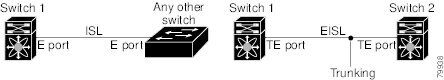
Trunking, also known as VSAN trunking, is a feature specific to switches in the Cisco MDS 9000 Family. Trunking enables interconnect ports to transmit and receive frames in more than one VSAN, over the same physical link. Trunking is supported on E ports and F ports (See Figure 5-1 and Figure 5-2).
This section includes the following topics:
- Trunking E Ports
- Trunking F Ports
- Key Concepts
- Trunking Protocols
- Trunk Modes
- Trunk-Allowed VSAN Lists and VF_IDs
Trunking E Ports
Trunking the E ports enables interconnect ports to transmit and receive frames in more than one VSAN, over the same physical link, using enhanced ISL (EISL) frame format.

Note![]() Trunking is not supported by internal ports on both the Cisco Fabric Switch for HP c_Class BladeSystem and the Cisco Fabric Switch for IBM BladeCenter.
Trunking is not supported by internal ports on both the Cisco Fabric Switch for HP c_Class BladeSystem and the Cisco Fabric Switch for IBM BladeCenter.
Trunking F Ports
Trunking F ports allows interconnected ports to transmit and receive tagged frames in more than one VSAN, over the same physical link.
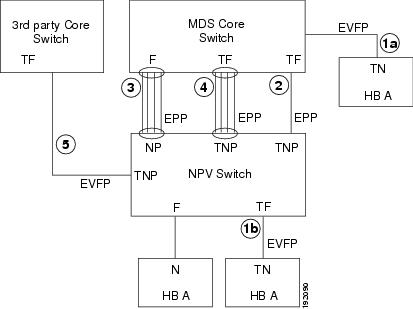
Figure 5-2 represents the possible trunking scenarios in a SAN with MDS core switches, NPV switches, third-party core switches, and HBAs.
|
|
|
|---|---|
F port trunk with N port.1 |
|
|
|
Key Concepts
The trunking feature includes the following key concepts:
- TE port—If trunk mode is enabled in an E port and that port becomes operational as a trunking E port, it is referred to as a TE port.
- TF port—If trunk mode is enabled in an F port (see the link 2 in Figure 5-2) and that port becomes operational as a trunking F port, it is referred to as a TF port.
- TN port—If trunk mode is enabled (not currently supported) in an N port (see the link 1b in Figure 5-2) and that port becomes operational as a trunking N port, it is referred to as a TN port.
- TNP port—If trunk mode is enabled in an NP port (see the link 2 in Figure 5-2) and that port becomes operational as a trunking NP port, it is referred to as a TNP port.
- TF PortChannel—If trunk mode is enabled in an F PortChannel (see the link 4 in Figure 5-2) and that PortChannel becomes operational as a trunking F PortChannel, it is referred to as TF PortChannel. Cisco Port Trunking Protocol (PTP) is used to carry tagged frames.
- TF-TN port link—A single link can be established to connect an F port to an HBA to carry tagged frames (see the link 1a and 1b in Figure 5-2) using Exchange Virtual Fabrics Protocol (EVFP). A server can reach multiple VSANs through a TF port without inter-VSAN routing (IVR).
- TF-TNP port link—A single link can be established to connect an TF port to an TNP port using the PTP protocol to carry tagged frames (see the link 2 in Figure 5-2). PTP is used because PTP also supports trunking PortChannels.
Note![]() The TF-TNP port link between a third-party NPV core and a Cisco NPV switch is established using the EVFP protocol.
The TF-TNP port link between a third-party NPV core and a Cisco NPV switch is established using the EVFP protocol.
- A Fibre Channel VSAN is called Virtual Fabric and uses a VF_ID in place of the VSAN ID. By default, the VF_ID is 1 for all ports. When an N port supports trunking, a pWWN is defined for each VSAN and called a logical pWWN. In the case of MDS core switches, the pWWNs for which the N port requests additional FC_IDs are called virtual pWWNs.
Trunking Protocols
The trunking protocol is important for trunking operations on the ports. The protocols enable the following activities:
- Dynamic negotiation of operational trunk mode.
- Selection of a common set of trunk-allowed VSANs.
- Detection of a VSAN mismatch across an ISL.
Table 5-1 specifies the protocols used for trunking and channeling.
|
|
|
|---|---|
TF-TN port link2 |
|
|
|
By default, the trunking protocol is enabled on E ports and disabled on F ports. If the trunking protocol is disabled on a switch, no port on that switch can apply new trunk configurations. Existing trunk configurations are not affected. The TE port continues to function in trunk mode, but only supports traffic in VSANs that it negotiated with previously (when the trunking protocol was enabled). Also, other switches that are directly connected to this switch are similarly affected on the connected interfaces. In some cases, you may need to merge traffic from different port VSANs across a non-trunking ISL. If so, disable the trunking protocol.
Note![]() We recommend that both ends of a trunking link belong to the same port VSAN. On certain switches or fabric switches where the port VSANs are different, one end returns an error and the other end is not connected.
We recommend that both ends of a trunking link belong to the same port VSAN. On certain switches or fabric switches where the port VSANs are different, one end returns an error and the other end is not connected.
Trunk Modes
By default, trunk mode is enabled on all Fibre Channel interfaces (Mode: E, F, FL, Fx, ST, and SD) on non-NPV switches. On NPV switches, by default, trunk mode is disabled. You can configure trunk mode as on (enabled), off (disabled), or auto (automatic). The trunk mode configuration at the two ends of an ISL, between two switches, determine the trunking state of the link and the port modes at both ends (see Table 5-2 ).
|
|
|
|||
|---|---|---|---|---|
|
|
|
|
|
|
|
|
|
|
|
|

Tip![]() The preferred configuration on the Cisco MDS 9000 Family switches is one side of the trunk set to auto and the other side set to on.
The preferred configuration on the Cisco MDS 9000 Family switches is one side of the trunk set to auto and the other side set to on.
Note![]() When connected to a third-party switch, the trunk mode configuration on E ports has no effect. The ISL is always in a trunking disabled state. In the case of F ports, if the third-party core switch ACC's physical FLOGI with the EVFP bit is configured, then EVFP protocol enables trunking on the link.
When connected to a third-party switch, the trunk mode configuration on E ports has no effect. The ISL is always in a trunking disabled state. In the case of F ports, if the third-party core switch ACC's physical FLOGI with the EVFP bit is configured, then EVFP protocol enables trunking on the link.
Trunk-Allowed VSAN Lists and VF_IDs
Each Fibre Channel interface has an associated trunk-allowed VSAN list. In TE-port mode, frames are transmitted and received in one or more VSANs specified in this list. By default, the VSAN range (1 through 4093) is included in the trunk-allowed list.
The common set of VSANs that are configured and active in the switch are included in the trunk-allowed VSAN list for an interface, and they are called allowed-active VSANs. The trunking protocol uses the list of allowed-active VSANs at the two ends of an ISL to determine the list of operational VSANs in which traffic is allowed.
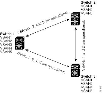
Switch 1 (see Figure 5-3) has VSANs 1 through 5, switch 2 has VSANs 1 through 3, and switch 3 has VSANs 1, 2, 4, and 5 with a default configuration of trunk-allowed VSANs. All VSANs configured in all three switches are allowed-active. However, only the common set of allowed-active VSANs at the ends of the ISL become operational (see Figure 5-3).
For all F, N, and NP ports, the default VF_ID is 1 when there is no VF_ID configured. The trunk-allowed VF_ID list on a port is same as the list of trunk-allowed VSANs. VF_ID 4094 is called the control VF_ID and it is used to define the list of trunk-allowed VF-IDs when trunking is enabled on the link.
If F port trunking and channeling is enabled, or if switchport trunk mode on is configured in NPV mode for any interface, or if NP PortChannel is configured, the VSAN and VF-ID ranges available for the configuration are as described in Table 5-3 .
|
|
|
|---|---|
Reserved VSANs and they are not available for user configuration. |
|
Note![]() If the VF_ID of the F port and the N port do not match, then no tagged frames can be exchanged.
If the VF_ID of the F port and the N port do not match, then no tagged frames can be exchanged.
Figure 5-3 Default Allowed-Active VSAN Configuration
You can configure a select set of VSANs (from the allowed-active list) to control access to the VSANs specified in a trunking ISL.
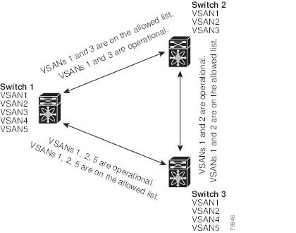
Using Figure 5-3 as an example, you can configure the list of allowed VSANs on a per-interface basis (see Figure 5-4). For example, if VSANs 2 and 4 are removed from the allowed VSAN list of ISLs connecting to switch 1, the operational allowed list of VSANs for each ISL would be as follows:
- The ISL between switch 1 and switch 2 includes VSAN 1 and VSAN 3.
- The ISL between switch 2 and switch 3 includes VSAN 1 and VSAN 2.
- The ISL between switch 3 and switch 1 includes VSAN 1, 2, and 5.
Consequently, VSAN 2 can only be routed from switch 1 through switch 3 to switch 2.
Figure 5-4 Operational and Allowed VSAN Configuration
Guidelines and Limitations
Trunking has the following configuration guidelines and limitations:
- General Guidelines and Limitations
- Upgrade and Downgrade Limitations
- Difference Between TE Ports and TF-TNP Ports
- Trunking Misconfiguration Examples
General Guidelines and Limitations
The trunking feature has the following general configuration guidelines and limitations:
- F ports support trunking in Fx mode.
- The trunk-allowed VSANs configured for TE, TF, and TNP links are used by the trunking protocol to determine the allowed active VSANs in which frames can be received or transmitted.
- If a trunking enabled E port is connected to a third-party switch, the trunking protocol ensures seamless operation as an E port.
- Trunking F ports and trunking F PortChannels are not supported on the following hardware:
–![]() 91x4 switches, if NPIV is enabled and used as the NPIV core switch.
91x4 switches, if NPIV is enabled and used as the NPIV core switch.
–![]() Generation 1 2-Gbps Fibre Channel switching modules.
Generation 1 2-Gbps Fibre Channel switching modules.
- On core switches, the FC-SP authentication will be supported only for the physical FLOGI from the physical pWWN.
- No FC-SP authentication is supported by the NPV switch on the server F ports.
- MDS does not enforce the uniqueness of logical pWWNs across VSANs.
- DPVM is not supported on trunked F port logins.
- The DPVM feature is limited to the control of the port VSAN, since the EVFP protocol does not allow changing the VSAN on which a logical pWWN has done FLOGI.
- The port security configuration will be applied to both the first physical FLOGI and the per VSAN FLOGIs.
- Trunking is not supported on F ports that have FlexAttach enabled.
- On MDS 91x4 core switches, hard zoning can be done only on F ports that are doing either NPIV or trunking. However, in NPV mode, this restriction does not apply since zoning is enforced on the core F port.
Upgrade and Downgrade Limitations
The trunking and channeling feature includes the following upgrade and downgrade limitations:
- When F port trunking or channeling is configured on a link, the switch cannot be downgraded to Cisco MDS SAN-OS Release 3.x and NX-OS Release 4.1(1b), or earlier.
- If you are upgrading from a SAN-OS Release 3.x to NX-OS Release 5.0(1), and you have not created VSAN 4079, the NX-OS software will automatically create VSAN 4079 and reserve it for EVFP use.
If VSAN 4079 is reserved for EVFP use, the switchport trunk allowed vsan command will filter out VSAN 4079 from the allowed list, as shown in the following example:
–![]() If you have created VSAN 4079, the upgrade to NX-OS Release 5.0(1) will have no affect on VSAN 4079.
If you have created VSAN 4079, the upgrade to NX-OS Release 5.0(1) will have no affect on VSAN 4079.
–![]() If you downgrade after NX-OS Release 5.0(1), the VSAN will no longer be reserved for EVFP use.
If you downgrade after NX-OS Release 5.0(1), the VSAN will no longer be reserved for EVFP use.
Difference Between TE Ports and TF-TNP Ports
In case of TE ports, the VSAN will in be initializing state when VSAN is coming up on that interface and when peers are in negotiating phase. Once the handshake is done, VSAN will be moved to up state in the successful case, and isolated state in the case of failure. Device Manager will show the port status as amber during initializing state and it will be green once VSANs are up.
This example shows the trunk VSAN states of a TE port:
In case of TF ports, after the handshake, one of the allowed VSANs will be moved to the up state. All other VSANs will be in initializing state even though the handshake with the peer is completed and successful. Each VSAN will be moved from initializing state to up state when a server or target logs in through the trunked F or NP ports in the corresponding VSAN.
Note![]() In case of TF or TNP ports, the Device Manager will show the port status as amber even after port is up and there is no failure. It will be changed to green once all the VSAN has successful logins.
In case of TF or TNP ports, the Device Manager will show the port status as amber even after port is up and there is no failure. It will be changed to green once all the VSAN has successful logins.
This example shows a TF port information after the port is in the up state:
This example shows the TF port information when a server logs in on noninternal FLOGI VSAN. VSAN 2183 is moved to the up state when the server logs in to VSAN 2183.
Trunking Misconfiguration Examples
If you do not configure the VSANs correctly, issues with the connection may occur. For example, if you merge the traffic in two VSANs, both VSANs will be mismatched. The trunking protocol validates the VSAN interfaces at both ends of a link to avoid merging VSANs (see Figure 5-5).
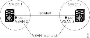
The trunking protocol detects potential VSAN merging and isolates the ports involved (see Figure 5-5).
The trunking protocol cannot detect merging of VSANs when a third-party switch is placed in between two Cisco MDS 9000 Family switches (see Figure 5-6).
Figure 5-6 Third-Party Switch VSAN Mismatch
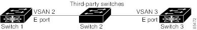
VSAN 2 and VSAN 3 are effectively merged with overlapping entries in the name server and the zone applications. Cisco DCNM-SAN helps detect such topologies.
Default Settings
Table 5-4 lists the default settings for trunking parameters.
|
|
|
|---|---|
Configuring Trunking
This section includes the following topics:
- Enabling the Cisco Trunking and Channeling Protocols
- Enabling the F Port Trunking and Channeling Protocol
- Configuring Trunk Mode
- Configuring an Allowed-Active List of VSANs
Enabling the Cisco Trunking and Channeling Protocols
This section describes how to enable the required trunking and channeling protocols.
Prerequisites
Detailed Steps
To enable or disable the Cisco trunking and channeling protocol, follow these steps:
|
|
|
|
|---|---|---|
Enabling the F Port Trunking and Channeling Protocol
This section describes how to enable the F port trunking and channeling protocol.
Prerequisites
Detailed Steps
To enable or disable the F port trunking and channeling protocol, follow these steps:
|
|
|
|
|---|---|---|
Enables the F port trunking and channeling protocol (default). |
||
Configuring Trunk Mode
Detailed Steps
To configure trunk mode, follow these steps:
|
|
|
|
|---|---|---|
Enables (default) the trunk mode for the specified interface. |
||
Configures the trunk mode to auto mode, which provides automatic sensing for the interface. |
Configuring an Allowed-Active List of VSANs
Detailed Steps
To configure an allowed-active list of VSANs for an interface, follow these steps:
|
|
|
|
|---|---|---|
Verifying Trunking Configuration
To display trunking configuration information, perform one of the following tasks:
For detailed information about the fields in the output from these commands, refer to the Cisco MDS NX-OS Command Reference.
The show interface command is invoked from the EXEC mode and displays trunking configurations for a TE port. Without any arguments, this command displays the information for all of the configured interfaces in the switch. See Examples 5-1 to 5-3 .
Example 5-1 Displays a Trunked Fibre Channel Interface
Example 5-2 Displays the Trunking Protocol
Example 5-3 Displays Per VSAN Information on Trunk Ports
Configuration Example for F Port Trunking
This example shows how to configure trunking and bring up the TF-TNP link between an F port in the NPIV core switch and an NP port in the NPV switch:
Step 1![]() Enable the F port trunking and channeling protocol on the MDS core switch:
Enable the F port trunking and channeling protocol on the MDS core switch:
Step 2![]() Enable NPIV on the MDS core switch:
Enable NPIV on the MDS core switch:
Step 3![]() Configure the port mode to auto, F, or Fx on the MDS core switch:
Configure the port mode to auto, F, or Fx on the MDS core switch:
Step 4![]() Configure the trunk mode to ON on the MDS core switch:
Configure the trunk mode to ON on the MDS core switch:
Step 5![]() Configure the port mode to NP on the NPV switch:
Configure the port mode to NP on the NPV switch:
Step 6![]() Configure the trunk mode to ON on the NPV switch:
Configure the trunk mode to ON on the NPV switch:
Step 7![]() Set the port administrative state on NPIV and NPV switches to ON:
Set the port administrative state on NPIV and NPV switches to ON:
Step 8![]() Save the configuration.
Save the configuration.
 Feedback