Chassis Components
This section describes the different components of the chassis.
Front View
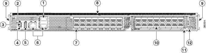
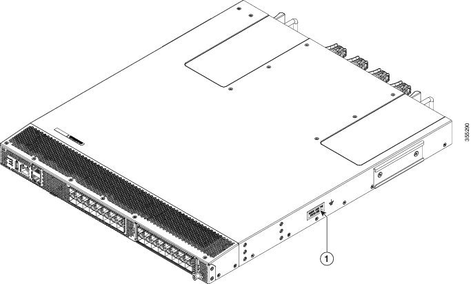
The following figure shows the front view of a Cisco MDS 9132T Switch:
|
1 |
Serial console port |
7 |
Fixed FC ports |
|
2 |
System status LED |
8 |
Airflow grill |
|
3 |
Power supply status LED |
9 |
Rack-mount mounting rails |
|
4 |
Fan status LED |
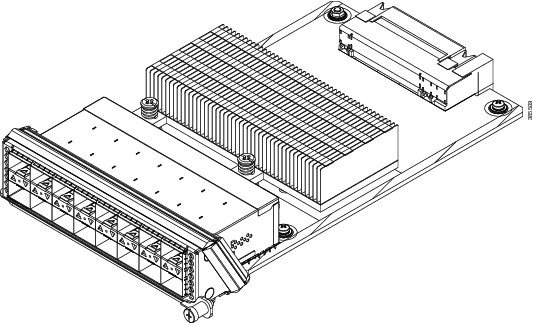
10 |
Linecard Expansion Module (LEM) |
|
5 |
USB port |
11 |
LEM ejector lever |
|
6 |
Two 10/100/1000 Mbps Ethernet management ports |
12 |
LEM locking screw |
|
1 |
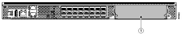
LEM slot 1 |
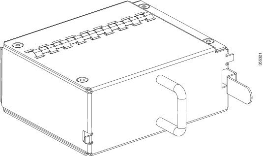
Rear View
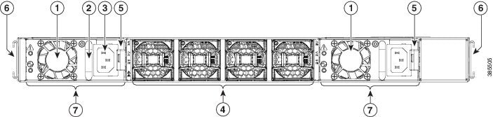
The following figure shows the rear view of a Cisco MDS 9132T Switch:
|
1 |
Power supply unit fans |
5 |
Power supply unit locking latches |
|
2 |
Power supply unit handle |
6 |
Rack-mount mounting rails |
|
3 |
Power receptacle |
7 |
Power supply units (2 units) |
|
4 |
Chassis fan modules (4 units) |
|
1 |
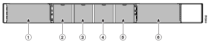
Power supply unit slot 1 |
4 |
Chassis fan module slot 3 |
|
2 |
Chassis fan module slot 1 |
5 |
Chassis fan module slot 4 |
|
3 |
Chassis fan module slot 2 |
6 |
Power supply unit slot 2 |
Grounding Point
The following figure shows the grounding point of a Cisco MDS 9132T Switch:
|
1 |
Grounding point |
Switch LEDs
The following table describes the chassis activity LEDs for a Cisco MDS 9132T switch.
 Note |
For switches running Cisco MDS NX-OS Release 8.3(1) or earlier, the fan status LED is green when four fans are installed and operational. On Cisco MDS NX-OS Release 8.3(2) or later, the fan status LED is green when two or four fans are installed and operational. |
|
Indicator |
Location |
Function |
Color |
Status |
State |
|---|---|---|---|---|---|
|
Power LED |
Front panel of the chassis |
Chassis Power/Health |
Off |
Off |
Either of the following conditions exists:
|
|
Green |
Solid On |
Both PSUs are installed and operational. |
|||
|
Red |
Solid On |
Either of the following conditions exists:
|
|||
|
Status LED |
Front panel of the chassis |
System Status |
Green |
Solid On |
All diagnostics have passed, Cisco NX-OS is running and the system is operational. |
|
Orange |
Solid On |
Any of the following conditions exists:
|
|||
|
Red |
Blinking |
Mismatched airflow direction observed in one of the following modules:
|
|||
|
Solid On |
One of the following conditions exists:
|
||||
|
Fan status |
Front panel of the chassis |
Fan health |
Green |
Solid on |
All fan modules are operational. |
|
Red |
Solid on |
Fan failure. |
|||
|
PSU Status Indicators |
Faceplate of each PSU |
PSU input/output |
Green |
Off |
No input to the PSU. |
|
Solid on |
PSU output is OK. |
||||
|
Blinking |
PSU output is not OK, but input is OK. |
||||
|
PSU operation |
Amber |
Off |
PSU is operating normally. |
||
|
Solid on |
One of the following conditions exists in the PSU: Over voltage Over current Over temperature Fan failure. |
||||
|
Blinking |
PSU has a fault, but is still operational. |
||||
|
Fan Status |
Faceplate of each fan module |
Fan module |
Green |
Solid on |
Fan module is operating normally. |
|
Amber |
Solid on |
All fans in the fan module have failed. |
The following table describes the Ethernet port LEDs for a Cisco MDS 9132T switch.
|
LED Position |
Status |
State |
|---|---|---|
|
Left |
Off |
There is no link. |
|
Solid Green |
Indicates a physical link. |
|
|
Right |
Off |
There is no activity. |
|
Blinking Amber |
Indicates activity. |
The following table describes the Fibre Channel port LEDs for a Cisco MDS 9132T switch.
|
Status |
State |
|---|---|
|
Solid Green |
The link is up. |
|
Regular Blinking Green |
The link is up and the port beacon is active. |
|
Intermittent Blinking Green |
The link is up (indicates traffic on the port). |
|
Solid Orange |
The link is disabled by the software. |
|
Blinking Orange |
A faulty condition exists. |
|
Off |
No link. |
 Feedback