Cisco IT Compute at Scale on Cisco ACI
Available Languages
Cisco IT Compute at Scale on Cisco ACI
This is the fourth white paper in a series of case studies that explain how Cisco IT deployed ACI to deliver improved business performance. These in-depth case studies cover the Cisco IT ACI data center design, migration to ACI, the ACI NetApp storage area network deployment, compute at scale with AVS, UCS, KVM, and VMware, server load balancing, and Tetration analytics. These white papers will enable field engineers and customer IT architects to assess the product, plan deployments, and exploit its application centric properties to flexibly deploy and manage robust highly scalable integrated data center and network resources.
Contributors to this white paper from the Cisco IT ACI Compute Team include Hugh Flanagan, Sr Engineer, Jason Stevens, Engineer, Benny Van De Voorde, Principal Engineer.
Version: 1.1, June 2020 – updated with copy edits for clarity.
Americas Headquarters
Cisco Systems, Inc.
170 West Tasman Drive
San Jose, CA 95134-1706 USA
Tel: 408 526-4000
800 553-NETS (6387)
Fax: 408 527-0883
THE SPECIFICATIONS AND INFORMATION REGARDING THE PRODUCTS IN THIS MANUAL ARE SUBJECT TO CHANGE WITHOUT NOTICE. ALL STATEMENTS, INFORMATION, AND RECOMMENDATIONS IN THIS MANUAL ARE BELIEVED TO BE ACCURATE BUT ARE PRESENTED WITHOUT WARRANTY OF ANY KIND, EXPRESS OR IMPLIED. USERS MUST TAKE FULL RESPONSIBILITY FOR THEIR APPLICATION OF ANY PRODUCTS.
THE SOFTWARE LICENSE AND LIMITED WARRANTY FOR THE ACCOMPANYING PRODUCT ARE SET FORTH IN THE INFORMATION PACKET THAT SHIPPED WITH THE PRODUCT AND ARE INCORPORATED HEREIN BY THIS REFERENCE. IF YOU ARE UNABLE TO LOCATE THE SOFTWARE LICENSE OR LIMITED WARRANTY, CONTACT YOUR CISCO REPRESENTATIVE FOR A COPY.
The Cisco implementation of TCP header compression is an adaptation of a program developed by the University of California, Berkeley (UCB) as part of UCB's public domain version of the UNIX operating system. All rights reserved. Copyright © 1981, Regents of the University of California.
NOTWITHSTANDING ANY OTHER WARRANTY HEREIN, ALL DOCUMENT FILES AND SOFTWARE OF THESE SUPPLIERS ARE PROVIDED “AS IS" WITH ALL FAULTS. CISCO AND THE ABOVE-NAMED SUPPLIERS DISCLAIM ALL WARRANTIES, EXPRESSED OR IMPLIED, INCLUDING, WITHOUT LIMITATION, THOSE OF MERCHANTABILITY, FITNESS FOR A PARTICULAR PURPOSE AND NONINFRINGEMENT OR ARISING FROM A COURSE OF DEALING, USAGE, OR TRADE PRACTICE.
IN NO EVENT SHALL CISCO OR ITS SUPPLIERS BE LIABLE FOR ANY INDIRECT, SPECIAL, CONSEQUENTIAL, OR INCIDENTAL DAMAGES, INCLUDING, WITHOUT LIMITATION, LOST PROFITS OR LOSS OR DAMAGE TO DATA ARISING OUT OF THE USE OR INABILITY TO USE THIS MANUAL, EVEN IF CISCO OR ITS SUPPLIERS HAVE BEEN ADVISED OF THE POSSIBILITY OF SUCH DAMAGES.
Any Internet Protocol (IP) addresses and phone numbers used in this document are not intended to be actual addresses and phone numbers. Any examples, command display output, network topology diagrams, and other figures included in the document are shown for illustrative purposes only. Any use of actual IP addresses or phone numbers in illustrative content is unintentional and coincidental.
This product includes cryptographic software written by Eric Young (eay@cryptsoft.com).
This product includes software developed by the OpenSSL Project for use in the OpenSSL Toolkit. (http://www.openssl.org/) This product includes software written by Tim Hudson (tjh@cryptsoft.com).
Cisco and the Cisco logo are trademarks or registered trademarks of Cisco and/or its affiliates in the U.S. and other countries. To view a list of Cisco trademarks, go to this URL: http:// www.cisco.com/go/trademarks. Third-party trademarks mentioned are the property of their respective owners. The use of the word partner does not imply a partnership relationship between Cisco and any other company. (1110R)
© 2020 Cisco Systems, Inc. All rights reserved
Table of Contents
Cisco IT Compute Infrastructure at Scale on ACI
ACI Fabric Optimizes Modern Data Center Traffic Flows
Transporting Inter-subnet Tenant Traffic
ACI Virtual Machine Manager Domains
Non-exclusive Use of Compute Pods by Multiple VM Controllers
Automated Provisioning of VLANs from Specified VLAN Pools
Cisco IT ACI with UCS Central Compute Case Study
Cisco IT Deployed the Cisco Application Virtual Switch
Cisco IT UCS Central Horizontal Striped Domain Deployment
Best Practices and Lessons Learned
Cisco IT Compute Infrastructure at Scale on ACI
Cisco IT's objective for data center compute infrastructure is to minimize compatibility issues between server, storage, and network devices while also reducing facilities costs. Cisco IT chose to deploy Application Centric Infrastructure (ACI) expecting that it provides an open, centralized way of managing complete pools of IT resources through a single control plane. The Cisco IT experience with this model shows that they can reduce capital costs, improve operational efficiencies and, ultimately, increase agility within the datacenter. Cisco IT is actively migrating its infrastructure entirely to Cisco ACI.
Cisco IT ACI environment deploys more than 450 UCS compute domains that yield dramatic improvements in business performance. Cisco IT could leverage modern UCS blades to consolidate from 2,500 to 600 blades (average of 4:1 consolidation) deployed in the larger data center-wide virtual machine migration domains of ACI, while reducing the UCS domain holdback by more than half. According to the Cisco IT compute team of Hugh Flanagan, Jason Stevens, and Jeffrey Liu, “There is simply no other way to manage large scale compute resource pools as effectively.” UCS upgrades previously could take up to two years to complete. Now, with ACI, they can plan upgrades in a week, and put them in production in a day with no down time. This white paper shows exactly how this is possible.
Cisco Data Center Scale
The scale of the Cisco IT data center deployments presents both migration opportunities and challenges. The Cisco IT organization operates multiple business application and engineering development data centers distributed around the world.
Cisco IT Worldwide Data Centers
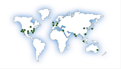
Cisco IT supports 141,000 employees (71,000 regular employees and 70,000 contractors) in 583 offices across more than 100 countries. The data centers occupy more than 269,000 sq. ft. of floor space and draw 30.1 MW of UPS power. More than 11,000 Cisco Unified Computing System™ (Cisco UCS®) blades are deployed with 92% of the servers virtualized in new data centers.
The infrastructure for the core business data centers (DC) is big. For example, the Allen, Texas DC includes 856 network devices that support 2300 traditional and private-cloud applications, run 8000 virtual machines, include 1700 Cisco Unified Computing System™ (Cisco UCS®) blades and 710 bare metal servers, with 14.5PB of NAS storage and 12PB of SAN storage. Cisco is driven to migrate to ACI because, as its data centers grow, quick and agile application deployment becomes increasingly challenging.
Cisco IT Standard ACI Data Center Fabric Today
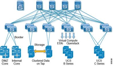
Cisco IT uses a standard ACI fabric topology in production data centers such as those in Research Triangle Park, North Carolina, Richardson, Texas, and Allen, Texas.
Cisco IT is evaluating the ACI v2.0 multipod feature for potential future deployment. Multipod enables provisioning multiple pods per floor, building, or region that provide Layer 3 connectivity between pods.
ACI Multipod – Evaluation for Future Enhancement
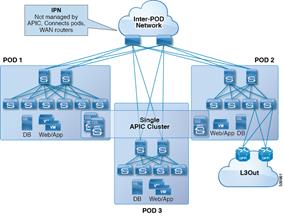
Multipod uses a single APIC cluster for all the pods; all the pods act as a single fabric.
ACI Logical Constructs
The ACI policy model is the basis for managing the entire fabric, including the infrastructure, authentication, security, services, applications, and diagnostics. Logical constructs in the policy model define how the fabric meets the needs of any of the functions of the fabric. From the point of view of data center design, the following three broad portions of the policy model are most relevant:
· Infrastructure policies that govern the operation of the equipment.
· Tenant policies that enable an administrator to exercise domain-based access control over the traffic within the fabric endpoint groups (EPGs) and between the fabric and external EPG devices and networks.
· Virtual Machine Manager (VMM) domain policies that group VM controllers with similar networking policy requirements.
Tenant policies are the core ACI construct that enable business application deployment agility. Tenants can map to logical segmentation/isolation constructs of public cloud service providers, including Amazon AWS, Microsoft Azure, or Google Cloud. Tenants can be isolated from one another or can share resources.
Within a tenant, bridge domains define a unique Layer 2 MAC address space and a Layer 2 flood domain if such flooding is enabled. A bridge domain must be linked to a context (VRF) and have at least one subnet that is associated with it. While a context (VRF) defines a unique IP address space, that address space can consist of multiple subnets. Those subnets are defined in one or more bridge domains that reference the corresponding context (VRF). Subnets in bridge domains can public (exported to routed connections), private (used only within the tenant) or shared across VRFs and across tenants.
The following figure provides an overview of the Cisco IT implementation of ACI tenant constructs.
Networking Design Logical View: EPG to BD Subnets to VRFs to External (L3Out)
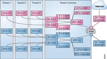
Cisco IT uses two VRFs within the fabric, one for DMZ/external and one for internal. This assures that there is complete isolation between the DMZ and internal security zones. Cisco IT minimizes the number of ACI VRFs they deploy for the following reasons:
· Simplicity – lots of cross talk among the thousands of production applications.
· Avoid IP overlap.
· Avoid route leaking.
There are important differences between VLANs and BDs.
· BDs, by default, do not flood broadcast, multicast, or unknown unicast packets.
· The policy model does not rely on VLANs to segment and control traffic between hosts.
· Hosts in different subnets can be in the same BD.
IP subnets are configured in the network by adding them to BDs. Many IP subnets can be configured per BD.
The ACI fabric can support a single BD per fabric with all subnets configured onto that single BD. Alternatively, the ACI fabric can be configured with a 1:1 mapping from BD to subnet. Depending on the size of the subnet, Cisco IT configures one to five subnets per BD.
It is important to note that from a forwarding perspective, the fabric is completely self-managing. That is, the ACI fabric does not need any specific configuration for L2/3 forwarding within the fabric.
The endpoint group (EPG) is the most important object in the policy model. Endpoints are devices connected directly or indirectly to the ACI fabric. EPGs are fully decoupled from the physical and logical topology. Endpoint examples include servers, virtual machines, network-attached storage, external Layer 2 or Layer 3 networks, or clients on the Internet. Policies apply to EPGs, never to individual endpoints. An administrator can statically configure an EPG, or automated systems such as VMware vCenter, OpenStack, or Microsoft Azure Pack can dynamically configure EPGs.
Virtual machine management connectivity to a hypervisor is an example of a configuration that uses a dynamic EPG. Once the virtual machine management domain is configured in the fabric, the hypervisor automatically triggers the dynamic configuration of EPGs that enable virtual machine endpoints to start up, move, and shut down as needed.
EPGs and bridge domains are associated with networking domains. An ACI fabric administrator creates networking domain policies that specify ports, protocols, VLAN pools, and encapsulation. A single tenant can use these policies exclusively, or they can be shared across the fabric. In ACI, an administrator can configure the following four kinds of networking domain profiles:
· VMM domain profiles are required for virtual machine hypervisor integration.
· Physical domain profiles are typically used for bare metal server attachment and management access.
· Bridged outside network domain profiles are typically used to connect a bridged external network trunk switch to a leaf switch in the ACI fabric.
· Routed outside network domain profiles are used to connect a router to a leaf switch in the ACI fabric.
The ACI administrator associates a domain with a VLAN pool. EPGs use the VLANs associated with a domain.
ACI Fabric Optimizes Modern Data Center Traffic Flows
The ACI architecture addresses the limitations of traditional data center design and provides robust support for the increased east-west traffic demands of modern data centers.
Today, application design drives east-west traffic from server to server through the data center access layer. Applications driving this shift include big data distributed processing designs like Hadoop, live virtual machine or workload migration as with VMware vMotion, server clustering, and multi-tier applications.
Traditional data center design with core, aggregation, and access layers (or collapsed core and access layers) reflects the demands of north-south traffic patterns. Client data comes in from the WAN or Internet, a server processes it, and then it exits the data center. Spanning Tree Protocol is required to block loops, which limits available bandwidth due to blocked links, and potentially forces traffic to take a suboptimal path. IEEE 802.1Q VLANs provide logical segmentation of Layer 2 boundaries or broadcast domains. However, VLAN use of network links is inefficient, requirements for device placements in the data center network can be rigid, and the VLAN maximum of 4094 VLANs can be a limitation. As IT departments and cloud providers build large multitenant data centers VLAN limitations become problematic.
A spine-leaf architecture addresses these limitations. The ACI spine-leaf fabric appears as a single switch to the outside world, capable of bridging and routing. However, moving Layer 3 routing to the access layer would limit the Layer 2 reachability that modern applications require. Applications like virtual machine workload mobility and some clustering software require Layer 2 adjacency between source and destination servers. By routing at the access layer, only servers connected to the same access switch with the same VLANs trunked down would be Layer 2-adjacent. In ACI, VXLAN solves this dilemma by decoupling Layer 2 domains from the underlying Layer 3 network infrastructure.
ACI Fabric VXLAN Encapsulation
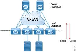
As traffic enters the fabric, ACI encapsulates and applies policy to it, forwards it as needed across the fabric through a spine switch (maximum two-hops), and de-encapsulates it upon exiting the fabric. Within the fabric, ACI uses the Intermediate System-to-Intermediate System Protocol (IS-IS) and the Council of Oracle Protocol (COOP) for all forwarding of endpoint-to-endpoint communications. This enables equal cost multipathing (ECMP), all ACI links to be active and fast reconvergence. For propagating routing information between software-defined networks within the fabric and routers external to the fabric, ACI uses the Multiprotocol Border Gateway Protocol (MP-BGP).
VXLAN in ACI
VXLAN is an industry-standard protocol that extends Layer 2 segments over Layer 3 infrastructure to build Layer 2 overlay logical networks. The ACI infrastructure Layer 2 domains reside in the overlay, with isolated broadcast and failure bridge domains. This approach allows the data center network to grow without risking creation of too large a failure domain.
All traffic in the ACI fabric is normalized as VXLAN packets. At ingress, ACI encapsulates external VLAN/VXLAN/NVGRE packets in a VXLAN packet. The following figure illustrates ACI encapsulation normalization.
ACI Encapsulation Normalization
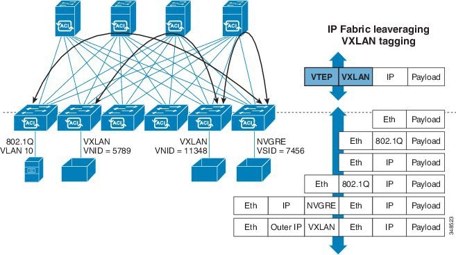
Forwarding in the ACI fabric is not limited to or constrained by the encapsulation type or encapsulation overlay network. An ACI bridge domain forwarding policy can be defined to provide standard VLAN behavior where required.
Because every packet in the fabric carries ACI policy attributes, ACI can consistently enforce policy in a fully distributed manner. ACI decouples application policy EPG identity from forwarding. The following figure illustrates how the ACI VXLAN header identifies application policy within the fabric.
ACI VXLAN Packet Format
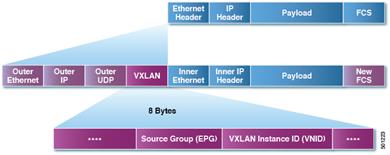
The ACI VXLAN packet contains both Layer 2 MAC address and Layer 3 IP address source and destination fields, which enables highly efficient and scalable forwarding within the fabric. The ACI VXLAN packed header source group field identifies the application policy endpoint group (EPG) to which the packet belongs. The VXLAN Instance ID (VNID) enables forwarding of the packet through tenant virtual routing and forwarding (VRF) domains within the fabric. The 24-bit VNID field in the VXLAN header provides an expanded address space for up to 16 million unique Layer 2 segments in the same network. This expanded address space gives IT departments and cloud providers greater flexibility as they build large multitenant data centers.
VXLAN enables ACI to deploy Layer 2 virtual networks at scale across the fabric underlay Layer 3 infrastructure. Application endpoint hosts can be flexibly placed in the data center network without concern for the Layer 3 boundary of the underlay infrastructure, while maintaining Layer 2 adjacency in a VXLAN overlay network.
Transporting Inter-subnet Tenant Traffic
The ACI fabric anycast gateway provides tenant default gateway functionality that routes between the ACI fabric VXLAN networks. For each tenant, the fabric provides a virtual default gateway that spans all the leaf switches assigned to the tenant. It does this at the ingress interface of the first leaf switch connected to the endpoint. Each ingress interface supports the default gateway interface and all the ingress interfaces across the fabric share the same router IP address and MAC address for a given tenant subnet.
The ACI fabric decouples the tenant endpoint address, its identifier, from the location of the endpoint that is defined by its locator or VXLAN tunnel endpoint (VTEP) address. Forwarding within the fabric is between VTEPs. The following figure shows decoupled identity and location in ACI.
ACI Decouples Identity and Location
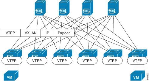
VXLAN uses VTEP devices to map tenants’ end devices to VXLAN segments and to perform VXLAN encapsulation and de-encapsulation. Each VTEP function has two interfaces: one is a switch interface on the local LAN segment to support local endpoint communication through bridging, and the other is an IP interface to the transport IP network.
The IP interface has a unique IP address that identifies the VTEP device on the transport IP network known as the infrastructure VLAN. The VTEP device uses this IP address to encapsulate Ethernet frames and transmits the encapsulated packets to the transport network through the IP interface. A VTEP device also discovers the remote VTEPs for its VXLAN segments and learns remote MAC Address-to-VTEP mappings through its IP interface.
The VTEP in ACI maps the internal tenant MAC or IP address to a location using a distributed mapping database. After the VTEP completes a lookup, the VTEP sends the original data packet encapsulated in VXLAN with the destination address of the VTEP on the destination leaf switch. The destination leaf switch de-encapsulates the packet and sends it to the receiving host. With this model, ACI uses a full mesh, single hop, loop-free topology without the need to use the spanning-tree protocol to prevent loops.
The VXLAN segments are independent of the underlying network topology; conversely, the underlying IP network between VTEPs is independent of the VXLAN overlay. It routes the encapsulated packets based on the outer IP address header, which has the initiating VTEP as the source IP address and the terminating VTEP as the destination IP address.
The following figure shows how routing within the tenant is done.
Layer 3 VNIDs Transport ACI Intersubnet Tenant Traffic
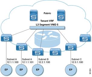
For each tenant VRF in the fabric, ACI assigns a single L3 VNID. ACI transports traffic across the fabric according to the L3 VNID. At the egress leaf switch, ACI routes the packet from the L3 VNID to the VNID of the egress subnet.
Traffic arriving at the fabric ingress that is sent to the ACI fabric default gateway is routed into the Layer 3 VNID. This provides very efficient forwarding in the fabric for traffic routed within the tenant. For example, with this model, traffic between 2 VMs belonging to the same tenant, on the same physical host, but on different subnets, only needs to travel to the ingress switch interface before being routed (using the minimal path cost) to the correct destination.
ACI Virtual Machine Manager Domains
ACI fabric virtual machine manager (VMM) domains enable an administrator to configure connectivity policies for virtual machine controllers.
In ACI, multiple VMM domains can coexist and interoperate. ACI virtual machine networking provides hypervisors from multiple vendors programmable and automated access to high-performance scalable virtualized data center infrastructure. ACI VM networking enables consistent enforcement of policies across both virtual and physical workloads managed by hypervisors from multiple vendors. The ACI Application Policy Infrastructure Controller (APIC) provides centralized troubleshooting, application health score, and virtualization monitoring.
ACI Multiple VM Controller Integration
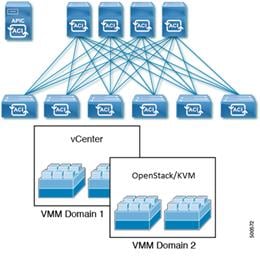
VMM domains provide support for the following:
· A common layer in the ACI fabric that enables scalable fault-tolerant support for multiple VM controller platforms.
· Multiple tenants within the ACI fabric.
· Automated static or dynamic VLAN allocations from specified VLAN pools.
· Micro segmentation that, when combined with intra-EPG isolation for bare metal and VM endpoints, provides policy driven automated complete endpoint isolation within application tiers.
Non-exclusive Use of Compute Pods by Multiple VM Controllers
The Cisco IT ACI solution integrates Cisco IT’s virtual compute controllers. Initially, most virtualized compute infrastructure is on VMWare. However, OpenStack/KVM is being aggressively pursued, which ACI can also integrate. Multiple VM hypervisors from different vendors can run concurrently on the ACI fabric, regardless of which switches are associated with the ACI VMM domains, and where the compute pods are connected to the ACI fabric. A single ACI leaf can be connected to both VMware VMs, and OpenStack/KVM VMs that are all running on a UCS B compute pod.
Cisco IT leverages the Cisco Advanced Virtual Switch (AVS), which is Cisco’s Nexus 1000v that has been modified to integrate into the ACI model. The most significant difference between the existing N1Kv and AVS, is that the virtual supervisor function has moved into the APIC controller. This provides a single point of management, configuration and control for all VMs.
Automated Provisioning of VLANs from Specified VLAN Pools
In ACI, VLAN pools are a shared resource comprised of blocks of VLAN identifiers. A VLAN pool can be static or dynamic, and consumed by multiple domains, including VMM domains. For dynamic VLAN pools, the APIC automatically assigns them; for static VLAN pools, and administrator explicitly assigns them.
A VMM domain can associate with only one dynamic VLAN pool. By default, the APIC dynamically assigns VLAN identifiers to EPGs that are associated with VMM domains. While dynamic allocation is the default and preferred configuration, an administrator can statically assign a VLAN identifier to an EPG instead.
ACI Automates VLAN Provisioning and VM Host Location Discovery
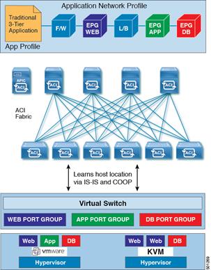
The ACI open API enables dynamically pushing the VLAN for an EPG into the VM virtual switch such as AVS or vDS. The ACI EPG is identified in the internal VXLAN packet source group field that is the port group in a VM virtual switch such as VMware vDS, or Cisco AVS.
VMM Domain EPG Association
The ACI fabric associates tenant application profile EPGs to VMM domains, either automatically by an orchestration component such as Microsoft Azure, or by an APIC administrator creating such configurations.
EPGs can map to multiple domains in the following ways:
· An encapsulation identifier that is either automatically managed by ACI, or statically selected by the administrator identifies an EPG within a VMM domain.
· EPGs can map to multiple physical (for bare metal servers) or VMM domains.
Whenever an EPG associates to a VMM domain, the administrator can choose the resolution and deployment preferences to specify when a policy should be pushed into leaf switches. When the fabric discovers a virtual endpoint, it pushes the policy into the leaf switches according to the immediate or on-demand resolution and deployment immediacy specifications for the EPG.
An EPG can span multiple VMM domains and a VMM domain can contain multiple EPGs.
ACI VMM Domain EPG Association
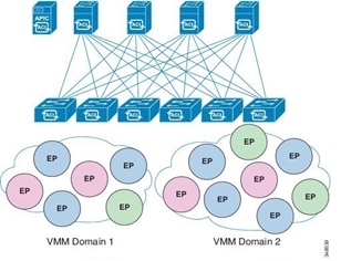
In the illustration above, endpoints (EP) of the same color are part of the same endpoint group. For example, all the green EPs are in the same EPG even though they are in two different VMM domains.
The following figure shows policy identification occurs as traffic moves between VMs across the ACI fabric.
ACI Policy Identification and Enforcement

Policy identification carried in every ACI packet enables consistent policy enforcement across the fabric in a fully distributed manner.
Cisco IT ACI with UCS Central Compute Case Study
Cisco ACI virtual machine networking provides hypervisors from multiple vendors programmable and automated access to high-performance scalable virtualized data center infrastructure. Programmability and automation are critical features of scalable data center virtualization infrastructure. ACI enables graceful scale out of network infrastructure, and Cisco UCS Central enables graceful compute to scale out. The result is a much easier to manage, much higher capacity, and much more productive data center.
The ACI open REST API enables virtual machine (VM) integration and orchestration of the ACI fabric. ACI VM networking enables consistent enforcement of policies across both physical and virtual compute workloads managed by hypervisors from multiple vendors. ACI attachable entity profiles easily enable VM mobility and placement of workloads anywhere in the ACI fabric. By reducing or eliminating manual configuration and manual errors, ACI multi-hypervisor VM automation enables virtualized data centers to support very large numbers of VMs reliably and cost effectively.
Unlike the limited mobility domains of traditional data center networks, ACI enables data center-wide mobility domains.
Prior UCS Limited Mobility Domains vs ACI Data Center-Wide Mobility Domain [
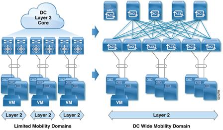
Constraints imposed by the Cisco IT prior UCS deployment model include the following:
· Each UCS was a silo in its own domain with no movement between domains.
· There was no standard holdback metric – depending on the model number of the equipment, an arbitrary holdback allocation ranged between 25-35%.
· A migration domain was a single UCS.
· Every time you deployed an application, you’d have to trunk down another VLAN, trunk it down in every UCS domain, update the UCS service profiles, configure the uplinks, etc.
· UCS limits the maximum number of allowed VLANs. VLAN technology addressing cannot exceed 4k VLANs.
· For every change (add, modify, or delete), these constraints added up to at least 2-3 hours work involving coordination and configuration by the network and compute teams to specify the VLAN name and number, which cluster to update, etc.
In the Cisco IT ACI UCS deployment, the ACI fabric VXLAN technology enables deploying up to 16 million VLANs in a highly automated way. ACI enables elastic workload placement and higher scalability of Layer 2 segmentation. With data center-wide mobility domains, ACI automatically provisions static or dynamic VLAN allocations from specified VLAN pools within the scope of a specified networking domain.
More Efficient Resource Pool Consumption
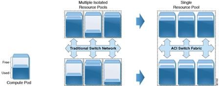
ACI automated data center-wide mobility domains enable much more efficient use of compute resource pools. This not only frees Cisco IT from the chore of managing the details of VLAN configurations, it also enables Cisco IT to easily evacuate a compute or IP storage system for maintenance purposes. Network, storage, compute upgrades (software or hardware), or infrastructure upgrades in data centers can be performed without application downtime.
Cisco IT Deployed the Cisco Application Virtual Switch
The Cisco Application Policy Infrastructure Controller (APIC) integrates with a VMware-based virtual environment by creating a distributed virtual switch mapped to the Cisco ACI environment in VMware vSphere vCenter. Cisco ACI customers need to choose the distributed virtual switch to use with Cisco ACI. Two options are available: Cisco Application Virtual Switch (AVS) included with ACI, and the VMware vSphere Distributed Switch (vDS). Cisco IT is using AVS.
Cisco Application Virtual Switch
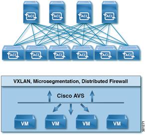
Although deployment flexibility that AVS provides is an important consideration, Cisco IT also has very strict criteria for failover convergence in its infrastructure. For instance, network, computing, and storage IP downtime in various network failover scenarios (using high availability) must be less than 5 seconds now, and less than 2 seconds within a year. Hence, Cisco IT tested the two distributed virtual switch options, Cisco AVS in VXLAN mode and VMware VDS, to see which would offer the best failover time compliant with requirements. Cisco IT choose Cisco AVS for its simplified management, greater scalability, better performance, flexible deployment options, and faster convergence.
AVS can use either VLAN or VXLAN encapsulation to forward traffic between the leaf switch and the VMware ESXi host. Connectivity to the Cisco ACI leaf through vDS is only VLAN-based in the absence of VMware vShield Manager. If VLAN encapsulation is used, each endpoint group (EPG) maps to a port group in the distributed virtual switch and receives a user-friendly name and a VLAN ID. The Cisco ACI fabric translates VLAN tags at the VMware port-group level into EPGs for policy application.
AVS Simplifies Deployment
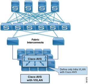
With AVS, the ACI APIC uses the OpFlex protocol to control the Virtual Ethernet Module (VEM) – a virtual line card embedded in each VMware vSphere (ESX) host, both control and data channels. This is sent over the ACI infrastructure VLAN (4093) configured during initial fabric bring-up. As such, with AVS, only a single VLAN needs to be trunked down from the ACI leaf switch to an ESXi or KVM server.
If VXLAN encapsulation is used, AVS acts as a VXLAN tunnel endpoint (VTEP) on the hypervisor, providing the capability to perform VXLAN tunneling over the infrastructure VLAN between the leaf switch and the host. In VXLAN mode, only the infrastructure VLAN is defined on the network infrastructure (if any) between the host and the leaf, resulting in simpler configuration. This approach is particularly useful in environments with blade servers in which blade switches lie between blade servers and leaf switches. AVS in VXLAN mode thus offered Cisco IT more flexibility in deployment compared to AVS in VLAN mode.
Cisco IT UCS Central Horizontal Striped Domain Deployment
In UCS Central, the entire compute pool is one large logical pool that can have hundreds of domains, each with multiple UCS cabinets. UCS Central makes this arrangement feasible at scale.
For its ACI deployment, Cisco IT adopted the following UCS Domain guidelines:
· M1 hardware is not integrated in this design.
· All hardware is placed under UCS Central control where it is globally managed (vs. locally which would be done within a single domain).
· No mixing of blade models in the same chassis.
· All efforts are made to have newer M3 hardware used for production and older M2 hardware for non-production.
Cisco IT reuses UCS Central service profile templates to apply service profiles across all its UCS domains. The service profile template is striped across multiple UCS domains.
Cisco IT Horizontal Striping Across UCS Cabinets
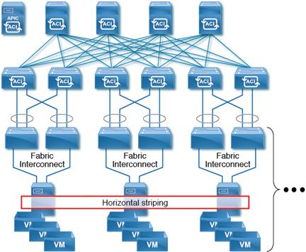
Horizontal striping is a fundamental shift in how Cisco IT lays out workloads. Previously, a migration domain was a single UCS that consisted of a pair of fabric interconnects with up to 20 chassis attached. The fabric interconnects have the configuration for all the chassis below them.
The same number of blades that had been in a vertical stack are now provisioned horizontally across the environment. Horizontal striping enables having different fault domains between the different UCS domains. Any single UCS domain is not reliant on any other UCS domain to function. Cisco IT configures a single ACI VMM domain across all UCS domains; all UCS domains have identical configurations (storage, CPU, memory, etc.).
Cisco IT UCS Service Profiles
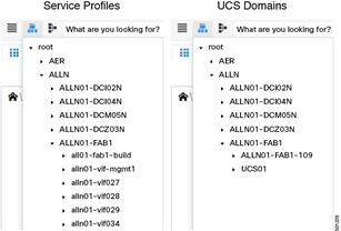
A service profile has a 1:1 relationship with a server, but copies of it, derived from the same template are applied across multiple servers. This simplifies managing large pools of compute resources.
When Cisco IT takes a UCS domain out of service, VM workloads can easily move to other domains. Cisco IT created a script that interfaces between vCenter and UCS Central that uses VMware maintenance mode vMotion to perform the horizontal mobility. This enables Cisco IT to pull blades out of service from the evacuated domain, and then use the same process to put blades back in service in the reactivated domain.
VMware VIFs and Openstack pods striped across the UCS domains provides a more dispersed solution with less impact on an individual UCS domain. In this new scenario, Cisco IT can take an entire UCS domain offline for upgrades and servicing, while all the workloads remain available.
Cisco IT Legacy UCS Build Workflow
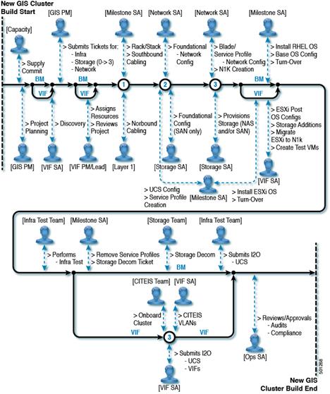
Cisco IT has 450 UCS domains. Prior to the ACI UCS Central deployment, upgrade maintenance was complicated by:
§ Change Freeze Windows
§ Maintenance Windows
§ Critical Client Workloads
The result was that UCS upgrades took up to 2 years to complete! Now, they can easily be done in a matter of weeks.
Opportunities that opened up with the Cisco IT ACI data center wide VM mobility domain striped UCS deployment model include the following:
· Consistent metric to specify the holdback capacity reserved in a single UCS domain. For example, if there are 8 UCS domains, the holdback in each domain is 12.5% (1/8 of a domain), if there are 10 UCS domains, the holdback in each domain is 10% (1/10 of a domain).
· Can take an entire UCS domain out of service for hardware swaps, upgrades, or maintenance, even during normal business hours. All UCS domains have identical configurations (storage, CPU, memory, etc.), so the VM workloads can be dynamically moved temporarily into the holdback capacity, then moved back when the task is complete. Previously, a UCS domain maintenance cutover window was up to eight hours; now, it is less than two hours.
· Huge time savings because ACI automates VLAN provisioning. Cisco data centers are large multi-tenant environments that provide service for potentially thousands of tenants. In the prior deployment model, thousands of customer applications were deployed on their own VLANs. From an operations perspective, the ACI deployment is much easier. Whereas it used to take at least 2-3 hours to perform the necessary application VLAN deployment tasks, ACI now accomplishes the same result instantly by automatically pushing an EPG into a VMM domain.
Operational Gains
In its ACI UCS deployment, Cisco IT could leveraged modern blades to consolidate from 2,500 to 600 blades (average of 4:1 consolidation) because of higher density 18 core dual CPU model B200 M4 blades (which support VXLAN offload) deployed in the larger fabric-wide virtual machine migration domains of ACI, while reducing the UCS domain holdback by more than half.
In the ACI any application anywhere scenario, any EPG can be leveraged on any compute resource within the fabric. Using VXLAN allows any compute resource to be immediately capable of running any VM with no further network configuration. In addition, the ACI stretched fabric feature allows for logically combining multiple datacenter halls into a single fabric. UCS Central allows massively scaling compute capacity while keeping policies and configuration consistent throughout.
Best Practices and Lessons Learned
Start off focused on the basics: add new features as you go, and test/certify new features and code prior to production deployment. Use lab environments for testing prior to production rollout, and check release notes for any important changes. Create a certification process with standard must have capabilities and verification, and document/track issues found. Use border leaf even / border leaf odd maintenance groups.
Build with automation in mind: create standard and reusable constructs, and document naming conventions for various objects to make readability and troubleshooting easier. Scripting skills will help you on your journey.
Use AVS and VXLAN where possible: Cisco IT found that using AVS for its vSwitch reduced configuration overhead (no need to trunk down huge amounts of VLANs) and provided better management and visibility when troubleshooting connectivity issues.
Schedule secure configuration backups/archives daily.
Security: Cisco IT found that Tetration machine learning effectively automates application dependency mapping. Tetration can export ACI contract specifications in various formats, including XMP, JSON, and YAML. The Tetration generated contracts specify how data flows are allowed between EPGs. Cisco IT incorporates the contract specifications into its standard YAML library which is then posted to ACI.
 Feedback
Contact Cisco
- Open a Support Case

- (Requires a Cisco Service Contract)