Connected Grid Switch Software Configuration Guide for IOS Release 15.0(2)ED
Bias-Free Language
The documentation set for this product strives to use bias-free language. For the purposes of this documentation set, bias-free is defined as language that does not imply discrimination based on age, disability, gender, racial identity, ethnic identity, sexual orientation, socioeconomic status, and intersectionality. Exceptions may be present in the documentation due to language that is hardcoded in the user interfaces of the product software, language used based on RFP documentation, or language that is used by a referenced third-party product. Learn more about how Cisco is using Inclusive Language.
- Updated:
- May 10, 2013
Chapter: Configuring VLAN Trunking Protocol
- Supported Hardware
- Information About VTP
- Configuring VTP
- Verifying VTP Configuration
Configuring VLAN Trunking Protocol
This chapter describes how to use the VLAN Trunking Protocol (VTP) and the VLAN database for managing VLANs with the Cisco CGS 2520 Switch and Cisco Connected Grid 10-port Ethernet Switch Module Interface Card (ESM).
For complete syntax and usage information for the commands used in this chapter, see the command reference listed in Supported Hardware.
Supported Hardware
|
|
|
|
|---|---|---|
Cisco 2500 Series Connected Grid Switches Configuration Guides |
||
CGS 2520 Switch Software Configuration Guide, 12.2(53)EX (Configuring VLANS) |
||
Catalyst 3750 Switch Command Reference, Cisco IOS Release 15.0(2)SE and Later |
||
Cisco Connected Grid 10-port Ethernet Switch Module Interface Card (ESM) |
Connected Grid Ethernet Switch Module Interface Card Getting Started Guide |
Information About VTP
VTP is a Layer 2 messaging protocol that maintains VLAN configuration consistency by managing the addition, deletion, and renaming of VLANs on a network-wide basis. VTP minimizes misconfigurations and configuration inconsistencies that can cause several problems, such as duplicate VLAN names, incorrect VLAN-type specifications, and security violations.
Before you create VLANs, you must decide whether to use VTP in your network. Using VTP, you can make configuration changes centrally on one or more switches (CGS 2520 or ESM) and have those changes automatically communicated to all the other switches in the network. Without VTP, you cannot send information about VLANs to other switches.
VTP is designed to work in an environment where updates are made on a single switch and are sent through VTP to other switches in the domain. It does not work well in a situation where multiple updates to the VLAN database occur simultaneously on switches in the same domain, which would result in an inconsistency in the VLAN database.
The switch supports VLANs, but the number of configured features affects the usage of the switch hardware. If the switch is notified by VTP of a new VLAN and the switch is already using the maximum available hardware resources, it sends a message that there are not enough hardware resources available and shuts down the VLAN. The output of the show vlan user EXEC command shows the VLAN in a suspended state.
VTP version 1 and version 2 support only normal-range VLANs (VLAN IDs 1 to 1005). Cisco IOS Release 12.2(52)SE and later support VTP version 3. VTP version 3 supports the entire VLAN range (VLANs 1 to 4094). Extended range VLANs (VLANs 1006 to 4094) are supported only in VTP version 3. You cannot convert from VTP version 3 to VTP version 2 if extended VLANs are configured in the domain.
These sections contain this conceptual information:
VTP Domain
A VTP domain (also called a VLAN management domain) consists of one switch or several interconnected switches under the same administrative responsibility sharing the same VTP domain name. A switch can be in only one VTP domain. You make global VLAN configuration changes for the domain.
By default, the switch is in the VTP no-management-domain state until it receives an advertisement for a domain over a trunk link (a link that carries the traffic of multiple VLANs) or until you configure a domain name. Until the management domain name is specified or learned, you cannot create or modify VLANs on a VTP server, and VLAN information is not propagated over the network.
If the switch receives a VTP advertisement over a trunk link, it inherits the management domain name and the VTP configuration revision number. The switch then ignores advertisements with a different domain name or an earlier configuration revision number.

When you make a change to the VLAN configuration on a VTP server, the change is propagated to all switches in the VTP domain. VTP advertisements are sent over all IEEE trunk connections, including IEEE 802.1Q. VTP dynamically maps VLANs with unique names and internal index associates across multiple LAN types. Mapping eliminates excessive device administration required from network administrators.
If you configure a switch for VTP transparent mode, you can create and modify VLANs, but the changes are not sent to other switches in the domain, and they affect only the individual switch. However, configuration changes made when the switch is in this mode are saved in the switch running configuration and can be saved to the switch startup configuration file.
For domain name and password configuration guidelines, see VTP Configuration Guidelines.
VTP Modes
You can configure a supported switch to be in one of the VTP modes listed in Table 5-1 .
|
|
|
|---|---|
In VTP server mode, you can create, modify, and delete VLANs, and specify other configuration parameters (such as the VTP version) for the entire VTP domain. VTP servers advertise their VLAN configurations to other switches in the same VTP domain and synchronize their VLAN configurations with other switches based on advertisements received over trunk links. VTP server is the default mode. Note In VTP server mode, VLAN configurations are saved in NVRAM. If the switch detects a failure while writing a configuration to NVRAM, VTP mode automatically changes from server mode to client mode. If this happens, the switch cannot be returned to VTP server mode until the NVRAM is functioning. |
|
A VTP client behaves like a VTP server and transmits and receives VTP updates on its trunks, but you cannot create, change, or delete VLANs on a VTP client. VLANs are configured on another switch in the domain that is in server mode. In VTP versions 1 and 2, in VTP client mode, VLAN configurations are not saved in NVRAM. In VTP version 3, VLAN configurations are saved in NVRAM in client mode. |
|
VTP transparent switches do not participate in VTP. A VTP transparent switch does not advertise its VLAN configuration and does not synchronize its VLAN configuration based on received advertisements. However, in VTP version 2 or version 3, transparent switches do forward VTP advertisements that they receive from other switches through their trunk interfaces. You can create, modify, and delete VLANs on a switch in VTP transparent mode. In VTP versions 1 and 2, the switch must be in VTP transparent mode when you create extended-range VLANs. VTP version 3 also supports creating extended-range VLANs in client or server mode. Refer to the Extended-Range VLANs section within the “Configuring VLANs” chapter of the CGS 2520 Switch Software Configuration Guide, 12.2(53)EX. When the switch is in VTP transparent mode, the VTP and VLAN configurations are saved in NVRAM, but they are not advertised to other switches. In this mode, VTP mode and domain name are saved in the switch running configuration, and you can save this information in the switch startup configuration file by using the copy running-config startup-config privileged EXEC command. |
|
A switch in VTP off mode functions in the same manner as a VTP transparent switch, except that it does not forward VTP advertisements on trunks. |
VTP Advertisements
Each switch in the VTP domain sends periodic global configuration advertisements from each trunk port to a reserved multicast address. Neighboring switches receive these advertisements and update their VTP and VLAN configurations as necessary.
Because trunk ports send and receive VTP advertisements, you must ensure that at least one trunk port is configured on the switch and that this trunk port is connected to the trunk port of another switch. Otherwise, the switch cannot receive any VTP advertisements. For more information on trunk ports, see the Configuring VLAN Trunks section of the “Configuring VLANs” chapter of the CGS 2520 Switch Software Configuration Guide, 12.2(53)EX.
VTP advertisements distribute this global domain information:
- VTP domain name
- VTP configuration revision number
- Update identity and update timestamp
- MD5 digest VLAN configuration, including maximum transmission unit (MTU) size for each VLAN.
- Frame format
VTP advertisements distribute this VLAN information for each configured VLAN:
- VLAN IDs (IEEE 802.1Q)
- VLAN name
- VLAN type
- VLAN state
- Additional VLAN configuration information specific to the VLAN type
In VTP version 3, VTP advertisements also include the primary server ID, an instance number, and a start index.
VTP Version 2
If you use VTP in your network, you must decide which version of VTP to use. By default, VTP operates in version 1.
VTP version 2 supports these features that are not supported in version 1:
- Token Ring support—VTP version 2 supports Token Ring Bridge Relay Function (TrBRF) and Token Ring Concentrator Relay Function (TrCRF) VLANs. For more information about Token Ring VLANs, see the Normal-Range VLANs section within the “Configuring VLANs” chapter of the CGS 2520 Switch Software Configuration Guide, 12.2(53)EX.
- Unrecognized Type-Length-Value (TLV) support—A VTP server or client propagates configuration changes to its other trunks, even for TLVs it is not able to parse. The unrecognized TLV is saved in NVRAM when the switch is operating in VTP server mode.
- Version-Dependent Transparent Mode—In VTP version 1, a VTP transparent switch inspects VTP messages for the domain name and version and forwards a message only if the version and domain name match. Because VTP version 2 supports only one domain, it forwards VTP messages in transparent mode without inspecting the version and domain name.
- Consistency Checks—In VTP version 2, VLAN consistency checks (such as VLAN names and values) are performed only when you enter new information through the CLI or SNMP. Consistency checks are not performed when new information is obtained from a VTP message or when information is read from NVRAM. If the MD5 digest on a received VTP message is correct, its information is accepted.
VTP Version 3
VTP version 3 supports these features that are not supported in version 1 or version 2:
- Enhanced authentication—You can configure the authentication as hidden or secret. When hidden, the secret key from the password string is saved in the VLAN database file, but it does not appear in plain text in the configuration. Instead, the key associated with the password is saved in hexadecimal format in the running configuration. You must reenter the password if you enter a takeover command in the domain. When you enter the secret keyword, you can directly configure the password secret key.
- Support for extended range VLAN (VLANs 1006 to 4094) database propagation. VTP versions 1 and 2 propagate only VLANs 1 to 1005. If extended VLANs are configured, you cannot convert from VTP version 3 to version 1 or 2.

Note![]() VTP pruning still applies only to VLANs 1 to 1005, and VLANs 1002 to 1005 are still reserved and cannot be modified.
VTP pruning still applies only to VLANs 1 to 1005, and VLANs 1002 to 1005 are still reserved and cannot be modified.
- Private VLAN support.
- Support for any database in a domain. In addition to propagating VTP information, version 3 can propagate Multiple Spanning Tree (MST) protocol database information. A separate instance of the VTP protocol runs for each application that uses VTP.
- VTP primary server and VTP secondary servers. A VTP primary server updates the database information and sends updates that are honored by all devices in the system. A VTP secondary server can only back up the updated VTP configurations received from the primary server to its NVRAM.
By default, all devices come up as secondary servers. You can enter the vtp primary privileged EXEC command to specify a primary server. Primary server status is only needed for database updates when the administrator issues a takeover message in the domain. You can have a working VTP domain without any primary servers. Primary server status is lost if the device reloads or domain parameters change, even when a password is configured on the switch.
- The option to turn VTP on or off on a per-trunk (per-port) basis. You can enable or disable VTP per port by entering the [ no ] vtp interface configuration command. When you disable VTP on trunking ports, all VTP instances for that port are disabled. You cannot set VTP to off for the MST database and on for the VLAN database on the same port.
When you globally set VTP mode to off, it applies to all the trunking ports in the system. However, you can specify on or off on a per-VTP instance basis. For example, you can configure the switch as a VTP server for the VLAN database but with VTP off for the MST database.
VTP Pruning
VTP pruning increases network available bandwidth by restricting flooded traffic to those trunk links that the traffic must use to reach the destination devices. Without VTP pruning, a switch floods broadcast, multicast, and unknown unicast traffic across all trunk links within a VTP domain even though receiving switches might discard them. VTP pruning is disabled by default.
VTP pruning blocks unneeded flooded traffic to VLANs on trunk ports that are included in the pruning-eligible list. Only VLANs included in the pruning-eligible list can be pruned. By default, VLANs 2 through 1001 are pruning eligible switch trunk ports. If the VLANs are configured as pruning-ineligible, the flooding continues. VTP pruning is supported in all VTP versions.
Figure 5-1 shows a switched network without VTP pruning enabled. Port 1 on Switch A and Port 2 on Switch D are assigned to the Red VLAN. If a broadcast is sent from the host connected to Switch A, Switch A floods the broadcast and every switch in the network receives it, even though Switches C, E, and F have no ports in the Red VLAN.
Figure 5-1 Flooding Traffic without VTP Pruning
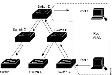
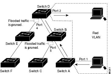
Figure 5-2 shows a switched network with VTP pruning enabled. The broadcast traffic from Switch A is not forwarded to Switches C, E, and F because traffic for the Red VLAN has been pruned on the links shown (Port 5 on Switch B and Port 4 on Switch D).
Figure 5-2 Optimized Flooded Traffic with VTP Pruning
Enabling VTP pruning on a VTP server enables pruning for the entire management domain. Making VLANs pruning-eligible or pruning-ineligible affects pruning eligibility for those VLANs on that trunk only (not on all switches in the VTP domain). (See Enabling VTP Pruning.)
VTP pruning takes effect several seconds after you enable it. VTP pruning does not prune traffic from VLANs that are pruning-ineligible. VLAN 1 and VLANs 1002 to 1005 are always pruning-ineligible; traffic from these VLANs cannot be pruned. Extended-range VLANs (VLAN IDs higher than 1005) are also pruning-ineligible.
VTP pruning is not designed to function in VTP transparent mode. If one or more switches in the network are in VTP transparent mode, you should do one of these:
- Turn off VTP pruning in the entire network.
- Turn off VTP pruning by making all VLANs on the trunk of the switch upstream to the VTP transparent switch pruning ineligible.
To configure VTP pruning on an interface, use the switchport trunk pruning vlan interface configuration command, refer to Changing the Pruning-Eligible List. VTP pruning operates when an interface is trunking. You can set VLAN pruning-eligibility, whether or not VTP pruning is enabled for the VTP domain, whether or not any given VLAN exists, and whether or not the interface is currently trunking.
Configuring VTP
This section contains the following configuration information:
- Default Settings
- VTP Configuration Guidelines
- Configuring VTP Mode
- Enabling the VTP Version
- Enabling VTP Pruning
- Changing the Pruning-Eligible List
- Configuring VTP on a Per-Port Basis
- Adding a VTP Client Switch to a VTP Domain
Default Settings
|
|
|
|---|---|
The mode is the same as the mode in VTP version 1 or 2 before conversion to version 3. |
|
VTP Configuration Guidelines
You use the vtp global configuration command to set the VTP password, the version, the VTP file name, the interface providing updated VTP information, the domain name, and the mode, and to disable or enable pruning. For more information about available keywords, see the command descriptions in the command reference for this release listed in Supported Hardware. The VTP information is saved in the VTP VLAN database. When VTP mode is transparent, the VTP domain name and mode are also saved in the switch running configuration file, and you can save it in the switch startup configuration file by entering the copy running-config startup-config privileged EXEC command. You must use this command if you want to save VTP mode as transparent if the switch resets.
When you save VTP information in the switch startup configuration file and restart the switch, the configuration is selected as follows:
- If the VTP mode is transparent in both the startup configuration and the VLAN database and the VTP domain name from the VLAN database matches that in the startup configuration file, the VLAN database is ignored (cleared). The VTP and VLAN configurations in the startup configuration file are used. The VLAN database revision number remains unchanged in the VLAN database.
- If the VTP mode or the domain name in the startup configuration does not match the VLAN database, the domain name and the VTP mode and configuration for the first 255 VLANs use the VLAN database information.
Domain Names
When configuring VTP for the first time, you must always assign a domain name. You must configure all switches in the VTP domain with the same domain name. Switches in VTP transparent mode do not exchange VTP messages with other switches, and you do not need to configure a VTP domain name for them.
Note![]() If NVRAM and DRAM storage is sufficient, all switches in a VTP domain should be in VTP server mode.
If NVRAM and DRAM storage is sufficient, all switches in a VTP domain should be in VTP server mode.
Passwords
You can configure a password for the VTP domain, but it is not required. If you do configure a domain password, all domain switches must share the same password and you must configure the password on each switch in the management domain. Switches without a password or with the wrong password reject VTP advertisements.
If you configure a VTP password for a domain, a switch that is booted without a VTP configuration does not accept VTP advertisements until you configure it with the correct password. After the configuration, the switch accepts the next VTP advertisement that uses the same password and domain name in the advertisement.
If you are adding a new switch to an existing network with VTP capability, the new switch learns the domain name only after the applicable password has been configured on it.
VTP Version
Follow these guidelines when deciding which VTP version to implement:
- All switches in a VTP domain must have the same domain name, but they do not need to run the same VTP version.
- A VTP version 2-capable switch can operate in the same VTP domain as a switch running VTP version 1 if version 2 is disabled on the version 2-capable switch (version 2 is disabled by default).
- If a switch running VTP version 1 but capable of running VTP version 2 receives VTP version 3 advertisements, it automatically moves to VTP version 2.
- If a switch running VTP version 3 is connected to a switch running VTP version 1, the VTP version 1 switch moves to VTP version 2, and the VTP version 3 switch sends scaled-down versions of the VTP packets so that the VTP version 2 switch can update its database.
- A switch running VTP version 3 cannot move to version 1 or 2 if it has extended VLANs.
- Do not enable VTP version 2 on a switch unless all of the switches in the same VTP domain are version-2-capable. When you enable version 2 on a switch, all of the version-2-capable switches in the domain enable version 2. If there is a version 1-only switch, it does not exchange VTP information with switches that have version 2 enabled.
- We recommend placing VTP version 1 and 2 switches at the edge of the network because they do not forward VTP version 3 advertisements.
- If there are TrBRF and TrCRF Token Ring networks in your environment, you must enable VTP version 2 or version 3 for Token Ring VLAN switching to function properly. To run Token Ring and Token Ring-Net, disable VTP version 2.
- VTP version 1 and version 2 do not propagate configuration information for extended-range VLANs (VLANs 1006 to 4094). You must configure these VLANs manually on each device. VTP version 3 supports extended-range VLANs. You cannot convert from VTP version 3 to VTP version 2 if extended VLANs are configured.
- When a VTP version 3 device trunk port receives messages from a VTP version 2 device, it sends a scaled-down version of the VLAN database on that particular trunk in VTP version 2 format. A VTP version 3 device does not send VTP version 2-formatted packets on a trunk unless it first receives VTP version 2 packets on that trunk port.
- When a VTP version 3 device detects a VTP version 2 device on a trunk port, it continues to send VTP version 3 packets, in addition to VTP version 2 packets, to allow both kinds of neighbors to coexist on the same trunk.
- A VTP version 3 device does not accept configuration information from a VTP version 2 or version 1 device.
- Two VTP version 3 regions can only communicate in transparent mode over a VTP version 1 or version 2 region.
- Devices that are only VTP version 1 capable cannot interoperate with VTP version 3 devices.
Configuration Requirements
When you configure VTP, you must configure a trunk port so that the switch can send and receive VTP advertisements to and from other switches in the domain.
For more information, see the Configuring VLAN Trunks section in the “Configuring VLANS” chapter of the CGS 2520 Switch Software Configuration Guide, 12.2(53)EX.
If you are configuring VTP on a cluster member switch to a VLAN, use the rcommand privileged EXEC command to log in to the member switch. For more information about the command, see the command reference for this release listed in Supported Hardware.
In VTP versions 1 and 2, when you configure extended-range VLANs on the switch, the switch must be in VTP transparent mode. VTP version 3 also supports creating extended-range VLANs in client or server mode.
Configuring VTP Mode
You can configure VTP mode as one of these:
- When a switch is in VTP server mode, you can change the VLAN configuration and have it propagated throughout the network.
- When a switch is in VTP client mode, you cannot change its VLAN configuration. The client switch receives VTP updates from a VTP server in the VTP domain and then modifies its configuration accordingly.
- When you configure the switch for VTP transparent mode, VTP is disabled on the switch. The switch does not send VTP updates and does not act on VTP updates received from other switches. However, a VTP transparent switch running VTP version 2 does forward received VTP advertisements on its trunk links.
- VTP off mode is the same as VTP transparent mode except that VTP advertisements are not forwarded.
- For VTP version 1 and version 2, if extended-range VLANs are configured on the switch, you cannot change VTP mode to client or server. You receive an error message, and the configuration is not allowed. VTP version 1 and version 2 do not propagate configuration information for extended range VLANs (VLANs 1006 to 4094). You must manually configure these VLANs on each device.
Note![]() For VTP version 1 and 2, before you create extended-range VLANs (VLAN IDs 1006 to 4094), you must set VTP mode to transparent by using the vtp mode transparent global configuration command. Save this configuration to the startup configuration so that the switch starts in VTP transparent mode. Otherwise, you lose the extended-range VLAN configuration if the switch resets and boots up in VTP server mode (the default).
For VTP version 1 and 2, before you create extended-range VLANs (VLAN IDs 1006 to 4094), you must set VTP mode to transparent by using the vtp mode transparent global configuration command. Save this configuration to the startup configuration so that the switch starts in VTP transparent mode. Otherwise, you lose the extended-range VLAN configuration if the switch resets and boots up in VTP server mode (the default).
- VTP version 3 supports extended-range VLANs. If extended VLANs are configured, you cannot convert from VTP version 3 to VTP version 2.
- If you configure the switch for VTP client mode, the switch does not create the VLAN database file (vlan.dat). If the switch is then powered off, it resets the VTP configuration to the default. To keep the VTP configuration with VTP client mode after the switch restarts, you must first configure the VTP domain name before the VTP mode.
Beginning in privileged EXEC mode, follow these steps to configure the VTP mode:
|
|
|
|
|---|---|---|
Configure the VTP administrative-domain name. The name can be 1 to 32 characters. All switches operating in VTP server or client mode under the same administrative responsibility must be configured with the same domain name. This command is optional for modes other than server mode. VTP server mode requires a domain name. If the switch has a trunk connection to a VTP domain, the switch learns the domain name from the VTP server in the domain. You should configure the VTP domain before configuring other VTP parameters. |
||
vtp mode { client | server | transparent | off } { vlan | mst | unknown } |
Configure the switch for VTP mode (client, server, transparent or off). |
|
(Optional) Set the password for the VTP domain. The password can be 8 to 64 characters. If you configure a VTP password, the VTP domain does not function properly if you do not assign the same password to each switch in the domain. See Configuring a VTP Version 3 Password for options available with VTP version 3. |
||
Verify your entries in the VTP Operating Mode and the VTP Domain Name fields of the display. |
||
(Optional) Save the configuration in the startup configuration file. Note Only VTP mode and domain name are saved in the switch running configuration and can be copied to the startup configuration file. |
When you configure a domain name, it cannot be removed; you can only reassign a switch to a different domain.
To return a switch in another mode to VTP server mode, use the no vtp mode global configuration command. To return the switch to a no-password state, use the no vtp password global configuration command.
This example shows how to configure the switch as a VTP server with the domain name eng_group and the password mypassword :
Configuring a VTP Version 3 Password
Beginning in privileged EXEC mode, follow these steps to configure the password when using VTP version 3:
To clear the password, enter the no vtp password global configuration command.
This example shows how to configure a hidden password and how it appears.
Configuring a VTP Version 3 Primary Server
Beginning in privileged EXEC mode, follow these steps on a VTP server to configure it as a VTP primary server (version 3 only), which starts a takeover operation:
This example shows how to configure a switch as the primary server for the VLAN database (the default) when a hidden or secret password was configured:
Enabling the VTP Version
VTP version 2 and version 3 are disabled by default.
- When you enable VTP version 2 on a switch, every VTP version 2-capable switch in the VTP domain enables version 2. To enable VTP version 3, you must manually configure it on each switch.
- With VTP versions 1 and 2, you can configure the version only on switches in VTP server or transparent mode. If a switch is running VTP version 3, you can change to version 2 when the switch is in client mode if no extended VLANs exist, no private VLANs exist, and no hidden password was configured.
- In TrCRF and TrBRF Token ring environments, you must enable VTP version 2 or VTP version 3 for Token Ring VLAN switching to function properly. For Token Ring and Token Ring-Net media, disable VTP version 2 must be disabled.
- VTP version 3 is supported on switches running Cisco IOS Release 12.2(52) SE or later.
For more information on VTP version configuration guidelines, see VTP Version.
Beginning in privileged EXEC mode, follow these steps to configure the VTP version:
|
|
|
|
|---|---|---|
Enable the VTP version on the switch. The default is VTP version 1. |
||
(Optional) Save the configuration in the startup configuration file. |
To return to the default VTP version 1, use the no vtp version global configuration command.
Enabling VTP Pruning
Pruning increases available bandwidth by restricting flooded traffic to those trunk links that the traffic must use to access the destination devices. You can only enable VTP pruning on a switch in VTP server mode.
Beginning in privileged EXEC mode, follow these steps to enable VTP pruning in the VTP domain:
To disable VTP pruning, use the no vtp pruning global configuration command.
With VTP versions 1 and 2, when you enable pruning on the VTP server, it is enabled for the entire VTP domain. In VTP version 3, you must manually enable pruning on each switch in the domain.
Only VLANs included in the pruning-eligible list can be pruned. By default, VLANs 2 through 1001 are pruning-eligible on trunk ports. Reserved VLANs and extended-range VLANs cannot be pruned. To change the pruning-eligible VLANs, see Changing the Pruning-Eligible List.
Changing the Pruning-Eligible List
The pruning-eligible list applies only to trunk ports. Each trunk port has its own eligibility list. VTP pruning must be enabled for this procedure to take effect.
Beginning in privileged EXEC mode, follow these steps to remove VLANs from the pruning-eligible list on a trunk port:
|
|
|
|
|---|---|---|
Identify an interface, and enter interface configuration mode. |
||
switchport trunk pruning vlan {add | except | none | remove} vlan-list [,vlan[,vlan[,,,]] |
Configure the list of VLANs allowed to be pruned from the trunk. ( See Enabling VTP Pruning.) add —Adds the defined list of VLANs to those currently set, instead of replacing the list. except —Lists the VLANs that should be calculated by inverting the defined list of VLANs. none —Indicates an empty list. remove —Removes the defined list of VLANs from those currently set instead of replacing the list. vlan-list —Is either a single VLAN number from 1 to 1005 or a continuous range of VLANs described by two VLAN numbers, the lesser one first, separated by a hyphen that represents the VLAN IDs of the allowed VLANs when this port is in trunking mode. For explanations about using the add, except, none, and remove keywords, refer to the command reference for this release listed in Supported Hardware. Separate nonconsecutive VLAN IDs with a comma and no spaces; use a hyphen to designate a range of IDs. Valid IDs are from 2 to 1001. VLANs that are pruning-ineligible receive flooded traffic. The default list of VLANs allowed to be pruned contains VLANs 2 to 1001. Note To return to the default pruning-eligible list of all VLANs, use the no switchport trunk pruning vlan interface configuration command. |
|
Verify your entries in the Pruning VLANs Enabled field of the command display. |
||
Configuring VTP on a Per-Port Basis
With VTP version 3, you can enable or disable VTP on a per-port basis. You can enable VTP only on ports that are in trunk mode. Incoming and outgoing VTP traffic are blocked, not forwarded.
Beginning in privileged EXEC mode, follow these steps to enable VTP on a port:
|
|
|
|
|---|---|---|
Identify an interface, and enter interface configuration mode. |
||
To disable VTP on the interface, use the no vtp interface configuration command.
Adding a VTP Client Switch to a VTP Domain
Before adding a VTP client to a VTP domain, always verify that its VTP configuration revision number is lower than the configuration revision number of the other switches in the VTP domain. Switches in a VTP domain always use the VLAN configuration of the switch with the highest VTP configuration revision number. With VTP versions 1 and 2, adding a switch that has a revision number higher than the revision number in the VTP domain can erase all VLAN information from the VTP server and VTP domain. With VTP version 3, the VLAN information is not erased.
Beginning in privileged EXEC mode, follow these steps to verify and reset the VTP configuration revision number on a switch before adding it to a VTP domain:
After resetting the configuration revision number, add the switch to the VTP domain.
Note![]() You can use the vtp mode transparent global configuration command to disable VTP on the switch and then to change its VLAN information without affecting the other switches in the VTP domain.
You can use the vtp mode transparent global configuration command to disable VTP on the switch and then to change its VLAN information without affecting the other switches in the VTP domain.
Verifying VTP Configuration
To view VTP configuration information, enter any or all of the following commands.
 Feedback