Cisco Catalyst Blade Switch 3120 for HP Hardware Installation Guide
Bias-Free Language
The documentation set for this product strives to use bias-free language. For the purposes of this documentation set, bias-free is defined as language that does not imply discrimination based on age, disability, gender, racial identity, ethnic identity, sexual orientation, socioeconomic status, and intersectionality. Exceptions may be present in the documentation due to language that is hardcoded in the user interfaces of the product software, language used based on RFP documentation, or language that is used by a referenced third-party product. Learn more about how Cisco is using Inclusive Language.
- Updated:
- February 5, 2008
Chapter: Configuring the Switch with the CLI-Based Setup Program
Configuring the Switch with the CLI-Based Setup Program
This appendix provides a quick installation and setup procedure for the switch module by using the command-line interface (CLI).

Note ![]() For detailed installation procedures, see Chapter 2, "Switch Installation." For product overview information, see Chapter 1, "Product Overview."
For detailed installation procedures, see Chapter 2, "Switch Installation." For product overview information, see Chapter 1, "Product Overview."
These are the major steps for a quick installation when using the CLI:
1. ![]() Accessing the CLI Through the Console Port
Accessing the CLI Through the Console Port
2. ![]() Connecting to the Console Port
Connecting to the Console Port
3. ![]() Completing the Initial Configuration
Completing the Initial Configuration
Accessing the CLI Through the Console Port
You can access the CLI on a configured or unconfigured switch module by connecting the console port of the switch module to the serial port on your PC or workstation and accessing the switch module through a Telnet session.
Connecting to the Console Port
Obtain and make note of this information from your network administrator before you begin the switch module installation:
•![]() Switch IP address
Switch IP address
•![]() Subnet mask (IP netmask)
Subnet mask (IP netmask)
•![]() Default gateway (router)
Default gateway (router)
•![]() Enable secret password (encrypted)
Enable secret password (encrypted)
•![]() Enable password (not encrypted)
Enable password (not encrypted)
•![]() Telnet password
Telnet password
•![]() SNMP community strings (optional)
SNMP community strings (optional)
Complete these steps:
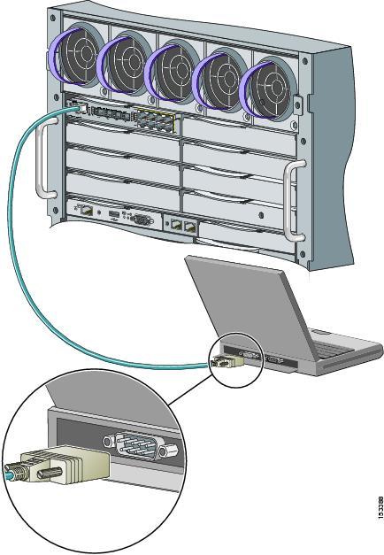
Step 1 ![]() Connect one end of the console cable to the switch module console port. Connect the other end of the cable to the serial port of the computer that is running the terminal emulation application. (See Figure C-1.)
Connect one end of the console cable to the switch module console port. Connect the other end of the cable to the serial port of the computer that is running the terminal emulation application. (See Figure C-1.)
You can use the mdix auto interface configuration command in the CLI to enable the automatic medium-dependent interface crossover (auto-MDIX) feature. When the auto-MDIX feature is enabled, the switch module detects the required cable type for copper Ethernet connections and configures the interfaces accordingly. Therefore, you can use either a crossover or a straight-through cable for connections to a copper 10/100/1000 or 1000BASE-T SFP module port on the switch module, regardless of the type of device on the other end of the connection.
For configuration information for this feature, refer to the switch module software configuration guide or the switch module command reference on Cisco.com.
Figure C-1 Connecting through the Switch Module Console Port
Step 2 ![]() Start the terminal emulation session so that you can see the output display from the power-on self-test (POST). The terminal-emulation software—a PC application such as Hyperterminal or ProcommPlus—makes communication between the switch module and your PC or terminal possible.
Start the terminal emulation session so that you can see the output display from the power-on self-test (POST). The terminal-emulation software—a PC application such as Hyperterminal or ProcommPlus—makes communication between the switch module and your PC or terminal possible.
Configure the baud rate and character format of the PC or terminal to match these console port default characteristics:
•![]() 9600 baud
9600 baud
•![]() 8 data bits
8 data bits
•![]() 1 stop bit
1 stop bit
•![]() No parity
No parity
•![]() None (flow control)
None (flow control)
Step 3 ![]() Wait for the switch module to complete the POST. It might take several minutes for the switch module to complete POST.
Wait for the switch module to complete the POST. It might take several minutes for the switch module to complete POST.
Step 4 ![]() Verify that POST has completed by confirming that the system and status LEDs remain green.
Verify that POST has completed by confirming that the system and status LEDs remain green.
If the switch module fails POST, the system LED turns amber. POST errors are usually fatal. Call Cisco Systems immediately if your switch module fails POST.
Step 5 ![]() Wait for the switch to complete initialization. When you see the prompt,
Wait for the switch to complete initialization. When you see the prompt, Press Return to Get Started!, press Return or Enter.
Step 6 ![]() Make sure that the system and status LEDs are green. This means that the switch module is operating properly.
Make sure that the system and status LEDs are green. This means that the switch module is operating properly.
Step 7 ![]() See the "Completing the Initial Configuration" section for instructions on setting up and initially configuring the switch module.
See the "Completing the Initial Configuration" section for instructions on setting up and initially configuring the switch module.
Completing the Initial Configuration
Follow these steps to complete the setup program and to create an initial configuration for the switch module.
Note ![]() For information about automatically configuring the switch module, see the "Assigning the Switch IP Address and Default Gateway" chapter in the switch module configuration guide.
For information about automatically configuring the switch module, see the "Assigning the Switch IP Address and Default Gateway" chapter in the switch module configuration guide.
Step 1 ![]() After you have pressed Enter or Return after the prompt to start the initial configuration setup program, enter yes at these prompts:
After you have pressed Enter or Return after the prompt to start the initial configuration setup program, enter yes at these prompts:
Would you like to terminate autoinstall? [yes]: yes
--- System Configuration Dialog ---
Continue with configuration dialog? [yes/no]: yes
At any point you may enter a question mark '?' for help.
Use ctrl-c to abort configuration dialog at any prompt.
Default settings are in square brackets '[]'.
Basic management setup configures only enough connectivity
for management of the system, extended setup will ask you
to configure each interface on the system
Would you like to enter basic management setup? [yes/no]: yes
Configuring global parameters:
Step 2 ![]() Enter a hostname for the switch module after the prompt, and press Return.
Enter a hostname for the switch module after the prompt, and press Return.
The hostname is limited to 20 characters. Do not use -n, where n is a number, as the last character in a hostname for any switch module.
Step 3 ![]() Enter an enable secret password, and press Return.
Enter an enable secret password, and press Return.
The password can be from 1 to 25 alphanumeric characters, can start with a number, is case sensitive, allows spaces, but ignores leading spaces. The secret password is encrypted, and the enable password is in plain text.
Step 4 ![]() Enter an enable password, and press Return.
Enter an enable password, and press Return.
Step 5 ![]() Enter a virtual terminal (Telnet) password, and press Return.
Enter a virtual terminal (Telnet) password, and press Return.
The password can be from 1 to 25 alphanumeric characters, is case sensitive, allows spaces, but ignores leading spaces.
Step 6 ![]() (Optional) Configure Simple Network Management Protocol (SNMP) by responding to the prompts.
(Optional) Configure Simple Network Management Protocol (SNMP) by responding to the prompts.
1. ![]() To configure SNMP later, press Return (which applies the default of no). If you accept the default, you can configure SNMP later through the CLI.
To configure SNMP later, press Return (which applies the default of no). If you accept the default, you can configure SNMP later through the CLI.
Configure SNMP Network Management? [no]:
2. ![]() To configure SNMP now, enter yes.
To configure SNMP now, enter yes.
Configure SNMP Network Management? [no]: yes
Community string [public]: public
Step 7 ![]() Enter the interface name (physical interface or VLAN name) of the interface that connects to the management network, and press Return.
Enter the interface name (physical interface or VLAN name) of the interface that connects to the management network, and press Return.
Enter vlan1 for the interface name at this prompt.
Step 8 ![]() To configure the interface, enter Yes after the prompt, and then enter the switch module IP address and subnet mask. Press Return.
To configure the interface, enter Yes after the prompt, and then enter the switch module IP address and subnet mask. Press Return.
The IP address and subnet mask shown here are examples:
Configuring interface Vlan1:
Configure IP on this interface? [yes]:
IP address for this interface [10.0.0.1]:
Subnet mask for this interface [255.255.255.0] : 255.255.255.0
Class A network is 10.0.0.1, 21 subnet bits; mask is /21
Step 9 ![]() Enter no when the prompt asks you if you would like to enable the switch module as a cluster command switch. This switch module will be a standalone switch.
Enter no when the prompt asks you if you would like to enable the switch module as a cluster command switch. This switch module will be a standalone switch.
Would you like to enable as a cluster command switch? [yes/no]: no
Note ![]() The Cisco Catalyst Blade Switch 3020 for HP does not support clustering.
The Cisco Catalyst Blade Switch 3020 for HP does not support clustering.
You have now completed the initial configuration of the switch module, and the switch module displays its initial configuration. An example of the output is shown here:
The following configuration command script was created:
hostname switch1
enable secret 5 $1$cagJ$e4LP91PNazfdADoNAZm6y0
enable password enable_password
line vty 0 15
password terminal-password
snmp-server community public
!
!
interface Vlan1
no shutdown
ip address 10.0.0.1 255.255.255.0
!
interface GigabitEthernet0/1
!
interface GigabitEthernet0/2
. . . (output truncated)
interface GigabitEthernet0/16
!
end
Step 10 ![]() These choices appear:
These choices appear:
[0] Go to the IOS command prompt without saving this config.
[1] Return back to the setup without saving this config.
[2] Save this configuration to nvram and exit.
If you want to save the configuration and use it the next time the switch reboots, save it
in NVRAM by selecting option 2.
Enter your selection [2]:2
Make your selection, and press Return.
Step 11 ![]() Disconnect the blade server serial port or the switch module console port from the PC. See the "Management Options" section on page 1-8 for information about managing the switch module.
Disconnect the blade server serial port or the switch module console port from the PC. See the "Management Options" section on page 1-8 for information about managing the switch module.
 Feedback