IP Video Surveillance Whitepapers
Bias-Free Language
The documentation set for this product strives to use bias-free language. For the purposes of this documentation set, bias-free is defined as language that does not imply discrimination based on age, disability, gender, racial identity, ethnic identity, sexual orientation, socioeconomic status, and intersectionality. Exceptions may be present in the documentation due to language that is hardcoded in the user interfaces of the product software, language used based on RFP documentation, or language that is used by a referenced third-party product. Learn more about how Cisco is using Inclusive Language.
- Updated:
- March 11, 2009
Chapter: Wide Area Application Services (WAAS) Integration
Wide Area Application Services (WAAS) Integration
Contents
Because of the benefits customers have realized by implementing the Cisco Wide Area Application Services (WAAS) between branch offices and central locations, the question of how WAAS might also provide bandwidth savings and TCP optimization for IP Video Surveillance traffic is frequently asked. The objective of this section is to understand the impact of WAAS on IP Video Surveillance traffic. Two types of video transport are discussed in this section:
•![]() Camera Feeds to Media Server (TCP transport of Motion JPG)
Camera Feeds to Media Server (TCP transport of Motion JPG)
•![]() Video Surveillance Operations Manager (VSOM) to client viewing station (HTTP)
Video Surveillance Operations Manager (VSOM) to client viewing station (HTTP)
The Wide Area Application Services (WAAS) for iSCSI document also provides a discussion on WAN transport of iSCSI video archives.
The topology for these scenarios is a branch router, a Cisco ISR 3845, with a VMSS network module (NME-VMSS-HP-32), and a WAAS network module (NME-WAE-522-K9). The campus location hosts a core Cisco Wide Area Application Engines (WAEs) and WAAS Central Manager. This topology builds upon the PfR integration topology where multiple WAN links exist between branch and campus location. The WAAS optimization of IPVS traffic across multiple WAN links managed by PfR was verified in this test phase. Included in this section are various Cisco IOS show commands and reports and exported data from the WAAS Central Manager, as well as verification from NetFlow exports from the routers in the tested topology.
Feature Overview
WAAS implements both data compression and optimization of the TCP session across the WAN between the branch (or edge) WAE and the core WAE. Two compression techniques are implemented: Persistent Lempel-Ziv (LZ) compression and Data Redundancy Elimination (DRE). LZ compression can achieve compression ratios in the order of 2:1, 5:1 or 100:1 if the data contains common strings or phrases. This form of compression is helpful for data that has not been previously seen or suppressed by DRE. DRE operates by maintaining a database of data that has been seen previously traversing the network. One advantage of DRE is that it is application-independent, meaning the redundant data may be part of a HTTP session or iSCSI archive and if commonalities exist, DRE can eliminate the redundant traffic. DRE can eliminate up to 99 percent of redundant network traffic and provide up to 100:1 compression.
However, both Motion JPEG and MPEG4 / H.264 camera feeds are compressed by the encoding function of the IP camera. Given this fact, the prospects of dramatic compression ratios by either LZ or DRE compression is unlikely. The data in this section supports that assumption.
WAAS uses the transport flow optimization (TFO) features to optimize TCP traffic. The specific techniques are as follows:
•![]() Windows scaling (RFC 1323)
Windows scaling (RFC 1323)
•![]() TCP Initial Window Size Maximization RFC 3390
TCP Initial Window Size Maximization RFC 3390
•![]() Increased Buffering
Increased Buffering
•![]() Selective Acknowledgement (SACK) (RFC 2018)
Selective Acknowledgement (SACK) (RFC 2018)
Note that a WAN transport with sufficient bandwidth to transport the video surveillance feeds are likely based on some form of Metro Ethernet service or DS3. DS3 bandwidth is capable of speeds up to 45 Mbps and Metro Ethernet may range in one to 10Mbps increments, using a 10/100/1000 Mbps interface handoff. Metro Ethernet services are usually policed by class or in aggregate by the service provider according to the contracted service. In the lab testing environment, between 10 to 20Mbps of WAN bandwidth was needed to transport the camera feeds for 1 to 4 cameras in the deployment. Given a viewing station observing 4 feeds simultaneously, with each feed at a target bit rate of 1Mbps, would therefore require approximately 4Mbps per viewing station. With these data rates as an example, it is obvious that viewing or archiving the video surveillance data across the WAN requires more bandwidth than a single T1 to the branch location.
Windows scaling and the enhanced buffering algorithm increase link utilization and take advantage of the available bandwidth. While these techniques may be optimal in a T1 WAN environment, the sheer amount of WAN bandwidth required for this deployment may render the advantages of these techniques less effective. Selective Acknowledgement provides efficient packet loss recovery and retransmission. If the WAN also transports UDP/RTP-based video, such as is the case with Telepresence and H.264/MPEG-4-based IP Video Surveillance, the loss needs to be closely monitored and addressed to preserve the video quality of these connectionless video feeds. Ideally, the WAN will exhibit very low loss and minimalize the need for selective acknowledgement.
Key Concepts
Some basic concepts must be understood to better understand the nature of the traffic and applications tested in this section. WAAS does not optimize traffic that is non-TCP (i.e., UDP or ICMP) traffic. Because H.264/MPEG-4 is typically RTP/UDP encapsulated, there is no optimization if this traffic is traversing the WAAS optimized WAN. Currently, all traffic between client viewing station and Media Server is TCP-based. Both MPEG-4 and Motion JPEG camera feeds, live, or archived are encapsulated in TCP. Motion JPEG camera feeds are typically TCP encapsulated. The Video Surveillance Media Server (VSMS) version tested is 6.0.0 and the Video Surveillance Operations Manager (VSOM) is 4.0.0. This version supports a Motion JPEG feed from the Axis 223M camera, TCP-based, and this camera was installed in the campus location to provide a TCP-based feed across the WAN. Currently, the Cisco Video Surveillance IP Camera (CIVS-IPC-2500) is not supported for MJPEG from VSMS 4.0.

Warning ![]() Future releases of the client viewing station code are slated to incorporate RTSP support that may implement MPEG-4 streams between the media server and viewing station to UDP.
Future releases of the client viewing station code are slated to incorporate RTSP support that may implement MPEG-4 streams between the media server and viewing station to UDP.
The WAAS tested version is 4.1.1c for the branch WAE, core WAE, and WAAS Central Manager. The video component in this version relates to Windows Media live video broadcasts that use RTSP over TCP. The video accelerator implemented by this feature eliminates duplicate video streams on the WAN and creates multiple streams to serve multiple clients on the LAN. This video acceleration is not applicable to IP Video Surveillance.
Traffic Optimization Overview
In the test topology, WAAS is added to the existing topology which is also performance Routing (PfR)-enabled. This overview and illustration is helpful to better understand how WAAS and PfR co-exist over the WAN. PfR manages two or more WAN links between the branch and campus router. PfR selects a path which meets the criteria, or the best path of so configured. In this video surveillance testing, sample configurations are shown which select the best path based on loss, or a combination of loss and delay. PfR is highly configurable and very granular; down to specific applications, if desired.
AS shown in Figure 1, PfR manages the WAN links between two routers, while WAAS intercepts traffic on the LAN interface of each router, routing the optimized traffic across the WAN interface in the IP routing table. PfR injects routes into the IP routing table or by policy-based routing (PBR).
Figure 1 Traffic Optimization Overview
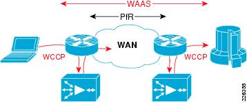
In these tests, traffic is intercepted with Web Cache Communication Protocol version 2 (WCCP v2) and redirected to the WAE. WCCP v2 supports any IP protocol (including any TCP or UDP). Intercepted TCP traffic is optionally a candidate for optimization. The WAE adds information to the TCP header to flag the next WAE that this traffic is being optimized. In the test lab, NetFlow is used to analyze the extent of WAN bandwidth savings. From the analysis of that data, it is noted that the WAAS sets the Explicit Congestion Notification (ECN) flag in the ToS byte. Because NetFlow v5 reports flows based on source/destination IP address, port, protocol, and ToS byte, a flow with the ECN bits set and one without is reported, even though they are actually part of the same flow if the ECN bits are ignored.
Topology
The tested topology is shown in Figure 2 discussed below.
Figure 2 WAAS Integration Topology
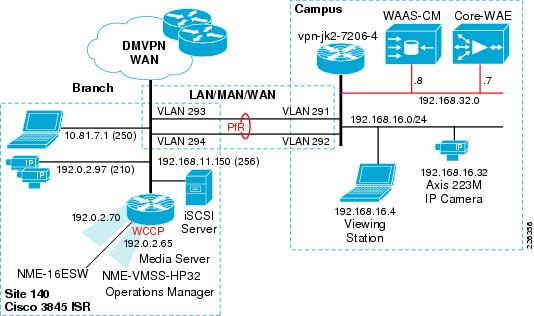
Some highlights of the topology are as follows:
•![]() The branch Cisco ISR 3845 houses both NME-WAE-522 and NME-VMSS-HP32
The branch Cisco ISR 3845 houses both NME-WAE-522 and NME-VMSS-HP32
•![]() A branch VLAN for MPEG-4 and Motion JPEG cameras
A branch VLAN for MPEG-4 and Motion JPEG cameras
•![]() The campus 7200 Series router has a VLANs for WAAS-CM and core WAE appliance
The campus 7200 Series router has a VLANs for WAAS-CM and core WAE appliance
•![]() A campus VLAN for viewing station and a Motion JPEG (Axis 223M) camera.
A campus VLAN for viewing station and a Motion JPEG (Axis 223M) camera.
•![]() The WAN is dual FastEthernet links with two delay generation devices to introduce loss, latency, and jitter
The WAN is dual FastEthernet links with two delay generation devices to introduce loss, latency, and jitter
PfR is implemented similarly on both the campus and branch router. WCCP is configured on the logical interface of the NME-VMSS-HP32 and on the VLAN of the viewing station/IP camera at the campus. Note that there is a Motion JPEG (Axis 223M) configured camera at the campus and transporting the video to the branch. Typically, a video surveillance deployment would not transport a video feed from the campus to a branch location for management and storage. It is not a recommended configuration, but it was inserted into the topology to demonstrate that WAAS could intercept TCP-based camera feeds across a WAN environment. Several customer deployments have been planned that require a single remote IP camera at an isolated location with the Media Server role at a larger branch deployment or campus location. This camera is included in the topology as a demonstration of that topology.
Role of WAAS Central Manager
The role of the WAAS Central Manager (CM) is to provide the network administrator with a graphical user interface for fault, configuration, performance of WAE(s). For detailed information on the WAAS CM , refer to the appropriate Cisco Wide Area Application Services Configuration Guide on www.cisco.com.
To illustrate the role of the WAAS CM, a screen snapshot is included showing the view of a remote WAE. To connect to the WAAS CM, the testbed campus PC accesses the WAAS CM by connecting to the IP address of the CM at port 8443 using the HTTP/SSL. For example:
https://192.168.32.8:8443/
Once validated, the branch WAE device can be selected. The screen snapshot in Figure 3 provides an idea of the GUI interface available to the network manager.
Figure 3 WAAS Central Manager Device Dashboard
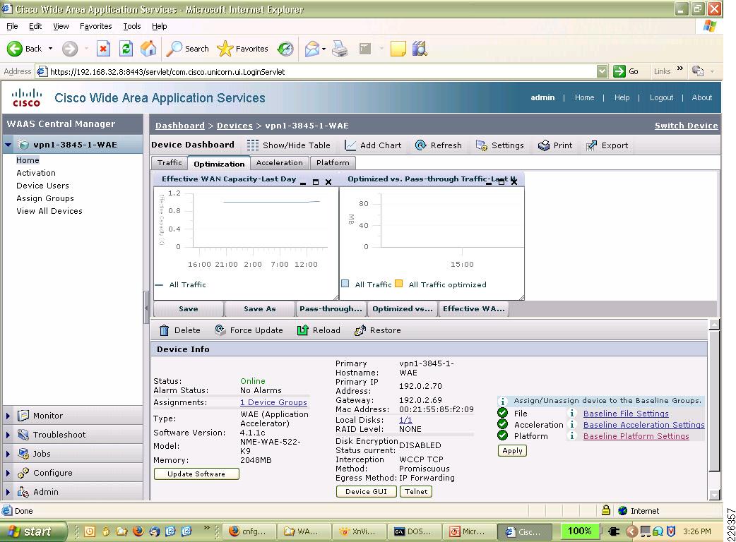
From the device dashboard screen shown above, the reports for the WAE can be viewed, the device can be managed by Telnet or a WEB browser, and other pertinent information like software version, alarms, IP address, and the MAC address can be displayed.
For the branch and core WAE to identify themselves to the CM, the configuration on the WAE must include the address of the CM; in the following example, 192.168.32.8.
vpn1-3845-1-WAE#sh run
! WAAS version 4.1.1c
! (build b16 Nov 5 2008)
!
device mode application-accelerator
!
hostname vpn1-3845-1-WAE
!
... [lines removed]
!
central-manager address 192.168.32.8
cms enable
!
! End of WAAS configuration
Once that is configured and the WAE contacts the CM, the remote WAE devices can be managed from the CM GUI interface.
Test Goals
The goal of this testing was to demonstrate PfR routing traffic over the WAN link that exhibits the best path between branch and campus. Once PfR is operational in the WAN, WAAS is implemented to optimize the TCP/HTTP traffic to and from the Video Management and Storage System (VMSS) logical interface in the branch Cisco 3845 ISR.
The Cisco IOS Release tested at the branch is c3845-adventerprisek9-mz.124-15.T5 using the NME-VMSS-HP-32 (version 4.0/6.0) network module and the NME-WAE-522-K9 network module using WAAS version 4.1.1.c. To verify the bandwidth savings, both NetFlow and the WAAS CM Report Effective WAN Capacity (bandwidth savings) data are used.
The approach is therefore to first describe the WAN characteristics, examine the PfR configuration, and then enable WAAS on the topology. The PfR configuration in this section builds upon the configuration in the previous section. In this testing, PfR is now managing both on packet loss and delay. Loss is the first priority and delay is the second priority. In testing, path changes are triggered by both loss and delay.
WAN Characteristics
On the two WAN links, a latency and packet loss tool is used to introduce loss, latency, and jitter. The values shown are applied in each direction. Both links have packet loss of one packet in every 10,000 packets, or 1/100th of 1 percent loss. Delay is in the range of 30 to 40 milliseconds on one link and 40 to 80 milliseconds on the other link. The variation in delay introduces jitter into the traffic. These values are shown in Figure 4.
Figure 4 WAN Characteristics - Latency, Jitter and Loss

At the beginning of the test, neither WAN link had any appreciable loss or delay, the tool is enabled during the test to simulate WAN links that are changing characteristics over a period of time.
PfR Configuration
The PfR configuration deployed in this testing uses the Fast Reroute feature. The Fast Reroute feature probes all exits continuously. This allows PfR to have the current state of all managed links reflected in its database. An explicitly configured active jitter probe (UDP jitter) is configured to characterize the delay, loss, and jitter of all exits. This probe also provides voice statistics such as Mean Opinion Score (MOS) although MOS is not, in this testing, used to make path selection determinations. PfR is selecting the best path, rather than a path that simply meets the criteria. Loss is the first priority, then delay as the second priority. The probe frequency is every 10 seconds.
The oer-map command that implements this configuration is shown as follows:
oer-map LOSS 10
sequence no. 8444249301975040, ...
match ip prefix-lists: CAMPUS
backoff 300 3000 300
delay threshold 80
holddown 300
periodic 0
*probe frequency 10
*mode route control
*mode monitor fast
*mode select-exit best
*loss relative 100
jitter threshold 20
mos threshold 3.60 percent 30
unreachable relative 50
next-hop not set
forwarding interface not set
*resolve loss priority 1 variance 10
*resolve delay priority 2 variance 10
*resolve utilization priority 12 variance 20
Forced Assigned Target List:
active-probe jitter 192.168.16.1 target-port 32014 codec g729a
* Overrides Default Policy Setting
This oer-map command is referenced in the configuration sample by the policy-rules statement shown later in this document.
Path Selection Based on Loss and Delay
PfR can select the best exit based on the loss and delay criteria. When PfR selects a new route, the change can be seen in the logging buffer of the master controller. During testing, this output was captured and is included here for review. Note that the route is changed for reason of delay in the first instance and for reason of packet loss in the second instance.
Dec 19 10:14:19.855 est: %OER_MC-5-NOTICE: Route changed Prefix 192.168.16.0/20,
BR 192.168.0.1, i/f Gi0/1.294, Reason Delay, OOP Reason None
Dec 19 10:19:56.862 est: %OER_MC-5-NOTICE: Route changed Prefix 192.168.16.0/20,
BR 192.168.0.1, i/f Gi0/1.293, Reason Loss, OOP Reason Loss
Given the low amount of loss in the test environment (1/100th of 1 percent) and that delay is incurred for all traffic, it is not unexpected to occasionally observe route changes alternate between loss and delay. In the Performance Routing (PfR) Integration document, it was shown that PfR can manage links based on loss, and there was a high amount of loss on one link verses the other. In this test, loss is very minimal and the same on both links during the test, while the links have different delay characteristics.
Branch Router Configuration Details
Relevant portions of the branch router configuration is shown below with imbedded annotations:
hostname vpn1-3845-1
!
WCCP Version 2 is enabled by default and WCCP services 61 and 62 (TCP promiscuous mode)
ip wccp 61
ip wccp 62
Cisco Express Forwarding (CEF) is required for PfR to function.
ip cef
!
oer master
policy-rules LOSS
logging
!
At least one internal interface and two or more external interfaces are required. The In3/0 interface is the NME-VMSS-HP32 logical interface.
border 192.168.0.1 key-chain PURPLE
interface Integrated-Service-Engine3/0 internal
interface GigabitEthernet0/1.293 external
interface GigabitEthernet0/1.294 external
interface GigabitEthernet0/1.210 internal
interface GigabitEthernet0/1.250 internal
!
For traffic not selected by the oer-map, learn mode is enabled to allow PfR to control routes for traffic exiting from VLANS 210 and 250 identified as internal interfaces above.
learn
throughput
delay
periodic-interval 0
monitor-period 1
expire after time 30
aggregation-type prefix-length 29
no max range receive
delay threshold 80
mode route control
mode select-exit best
!
The border router and master controller are both configured on this branch router, the key-chain of PURPLE is not shown, but is a requirement of PfR.
oer border
local Loopback0
master 192.168.0.1 key-chain PURPLE
!
The WAN interfaces are VLAN 293 and 294, these VLANs attach to the delay and loss appliance.
interface GigabitEthernet0/1.293
description To vpn-jk2-7206-1 for PfR
encapsulation dot1Q 293
ip address 192.168.15.6 255.255.255.252
!
interface GigabitEthernet0/1.294
description To vpn-jk2-7206-1 for PfR
encapsulation dot1Q 294
ip address 192.168.15.2 255.255.255.252
!
!
interface Integrated-Service-Engine2/0
description NME-WAE-522-K9
...
ip wccp redirect exclude in
!
This interface is an internal interface for PfR and is configured for WCCP redirection; therefore, traffic entering and leaving this interface are candidates for WAAS optimization.
interface Integrated-Service-Engine3/0
description NME-VMSS-HP32
ip address 192.0.2.64 255.255.255.254
ip wccp 61 redirect in
ip wccp 62 redirect out
...
PfR requires parent routes in the routing table. These routes identify the campus subnet of the viewing station and IP camera. The corresponding prefix-list selects traffic for the oer-map.
!
ip route 192.168.16.0 255.255.240.0 192.168.15.1 name OER_Parent
ip route 192.168.16.0 255.255.240.0 192.168.15.5 name OER_Parent
ip prefix-list CAMPUS seq 5 permit 192.168.16.0/20
!
The oer-map shown was also shown previously in this section.
oer-map LOSS 10
match traffic-class prefix-list CAMPUS
set mode select-exit best
set mode route control
set mode monitor fast
set resolve loss priority 1 variance 10
set resolve delay priority 2 variance 10
set loss relative 100
set active-probe jitter 192.168.16.1 target-port 32014 codec g729a
set probe frequency 10
!
end

Note ![]() The target of the active-probe defined above is the campus router with an IP address of 192.168.16.1. This router is also contains a similar PfR configuration. The UDP jitter probe requires the ip sla responder command in the configuration.
The target of the active-probe defined above is the campus router with an IP address of 192.168.16.1. This router is also contains a similar PfR configuration. The UDP jitter probe requires the ip sla responder command in the configuration.
PfR Verification
To verify PfR is managing the path to the campus network prefix where the viewing station and IP camera resides, the output of the show oer master prefix detail command is shown.
vpn1-3845-1#show oer masert prefix detail
Prefix: 192.168.16.0/20
State: INPOLICY Time Remaining: @0
Policy: 10
Most recent data per exit
Border Interface PasSDly PasLDly ActSDly ActLDly
*192.168.0.1 Gi0/1.294 0 0 75 75
192.168.0.1 Gi0/1.293 0 0 128 128
Most recent voice data per exit
Border Interface ActSJit ActPMOS ActSLos ActLLos
*192.168.0.1 Gi0/1.294 4 0 0 0
192.168.0.1 Gi0/1.293 11 0 0 0
Latest Active Stats on Current Exit:
Type Target TPort Attem Comps DSum Min Max Dly
jitter 192.168.16.1 32014 1 100 7510 1 106 75
jitter 192.168.16.1 32014 1 100 7490 1 106 74
jitter 192.168.16.1 32014 1 100 7458 1 106 74
jitter 192.168.16.1 32014 1 100 7564 1 106 75
jitter 192.168.16.1 32014 1 100 7527 1 106 75
Latest Active Voice Stats on Current Exit:
Type Target TPort Codec Attem Comps JitSum MOS
jitter 192.168.16.1 32014 g729a 1 100 413 4.06
jitter 192.168.16.1 32014 g729a 1 100 443 4.06
jitter 192.168.16.1 32014 g729a 1 100 451 4.06
jitter 192.168.16.1 32014 g729a 1 100 425 4.06
jitter 192.168.16.1 32014 g729a 1 100 392 4.06
...
In the above output, under Most recent data per exit, the active short and long-term delay values are 75 and 128 milliseconds. This is consistent with the WAN characteristics described previously. Also, the active short-term jitter is 4 and 11 milliseconds, which is a result of the range of latency values introduced by the test tool on each link.
WAAS Implementation
WAAS is also tested and documented in the V3PN large scale IPSec aggregation testbed and included in the following document:
•![]() Transport Diversity: Performance Routing (PfR) Design Guide
Transport Diversity: Performance Routing (PfR) Design Guide
The traffic profile used in the PfR and WAAS testing consisted of VoIP and data. The testing referenced here, WCCP enabled on the VMSS logical interface and therefore the target traffic for optimization is the HTTP requests the Client Viewing Station (Internet Explorer) makes to the VSOM web server. The nature of this traffic is video feeds displayed on the PC as well as the underlying web interface. Because in this phase of testing the Axis 223M camera is also located on the campus subnet, the TCP session for the Motion JPEG is also traversing the WAN to the Media Server IP address under the VMSS logical interface. This traffic is therefore also a candidate for optimization.
Figure 5 illustrates these flows to and from the VMSS logical interface.
Figure 5 Traffic Flows Optimized by WAAS
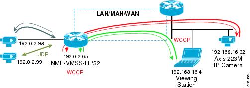
The flow from the IP camera to the Media Server is Motion JPEG (MJPEG) is at 5 video frames per second. The flows between VSOM and the Viewing Station are MJPEG/MPEG-4 (three cameras) along with the the HTTP control traffic. To verify these flows are candidates for optimization, the accelerated flows can be displayed on the branch WAE network module as shown in the following example:
vpn1-3845-1-WAE#show statistics connection all
D:DRE,L:LZ,T:TCP Optimization,
C:CIFS,E:EPM,G:GENERIC,H:HTTP,M:MAPI,N:NFS,V:VIDEO
ConnID Source IP:Port Dest IP:Port PeerID Accel
20334 192.0.2.65:36908 192.168.16.32:80 0:14:5e:85:54:7b THDL
20467 192.168.16.4:65488 192.0.2.65:80 0:14:5e:85:54:7b THDL
20468 192.168.16.4:65485 192.0.2.65:80 0:14:5e:85:54:7b THDL
20469 192.168.16.4:65482 192.0.2.65:80 0:14:5e:85:54:7b THDL
20489 192.168.16.4:65508 192.0.2.65:80 0:14:5e:85:54:7b THDL
Local IP:Port Remote IP:Port Peer ID ConnType
192.0.2.98:80 192.0.2.65:41233 N/A PT No Peer
192.0.2.65:41233 192.0.2.98:80 N/A PT No Peer
There are a total of five TCP/HTTP flows being optimized by TFO and targeted for DRE and LZ compression. This is signified by the THDL designation at the right of each connection detail line. The two flows that are listed as `No Peer' are the camera feeds on the branch LAN to the Media Server. These are not optimized because there is no WAN transport of these feeds, the camera feeds are local to the router.
Table of Effective Capacity
In the test results reported here, data is collected for over a hour and the results from the WAAS CM are shown Table 1. These results are summarized from an export of the device dashboard to a CSV file and analyzed. The following table represents the Effective WAN Capacity report for the remote (vpn1-3845-1-WAE) WAE.
The WAN bandwidth savings is shown at less than 10 percent. As a point of reference, the test results in the Transport Diversity: Performance Routing (PfR) Design Guide demonstrated compression ratios in the range of 3:1 to over 40:1 for Web and File Transfer sessions generated by Chariot/IXIA. From this, it can be concluded that data traffic is more compressible than the video traffic used in this test.
WCCP Configuration
This section includes the WCCP configurations on the campus and branch router.
Campus Router
The relevant WCCP configuration for the campus router is as follows:
hostname vpn-jk2-7206-1
!
ip wccp 61
ip wccp 62
ip cef
!
interface FastEthernet0/1.216
description CAMPUS with IP Cameras and PC
encapsulation dot1Q 216
ip address 192.168.16.1 255.255.240.0
ip wccp 61 redirect in
ip wccp 62 redirect out
!
interface FastEthernet0/1.232
description CAMPUS with WAAS CM and Core WAE
encapsulation dot1Q 232
ip address 192.168.32.1 255.255.240.0
ip wccp redirect exclude in
!
end
Branch Router
The relevant WCCP configuration for the branch routers is as follows:
hostname vpn1-3845-1
!
ip wccp 61
ip wccp 62
ip cef
!
interface Integrated-Service-Engine2/0
description NME-WAE-522-K9
ip address 192.0.2.69 255.255.255.252
ip wccp redirect exclude in
service-module ip address 192.0.2.70 255.255.255.252
service-module ip default-gateway 192.0.2.69
no keepalive
interface Integrated-Service-Engine3/0
description NME-VMSS-HP32
ip address 192.0.2.64 255.255.255.254
ip wccp 61 redirect in
ip wccp 62 redirect out
ip flow ingress
ip route-cache flow
service-module external ip address 192.168.11.2 255.255.255.0
service-module ip address 192.0.2.65 255.255.255.254
service-module ip default-gateway 192.0.2.64
no keepalive
!
Summary
Video feeds from IP Video Surveillance cameras to the Media Server are TCP-based when the camera is configured for Motion JPEG. Additionally, viewing live or archived feeds through VSOM by a client viewing stations is also TCP/HTTP based for feeds which are either MJPEG or MPEG-4. While TCP-based traffic can be optimized and compressed by WAAS, for this video traffic the compression is on the order of less than 10 percent. Video feeds are compressed by the encoder of the IP camera before being transported over the IP network. Additional compression by WAAS does not provide as dramatic savings as is the case with typical user data traffic.
However, both WAAS and PfR can be implemented effectively together and PfR is shown to manage multiple WAN links and select the path with the least loss and lowest delay.
 Feedback