Cisco Virtualized Multi-Tenant Data Center, Version 2.0 Large Pod Design Guide
Bias-Free Language
The documentation set for this product strives to use bias-free language. For the purposes of this documentation set, bias-free is defined as language that does not imply discrimination based on age, disability, gender, racial identity, ethnic identity, sexual orientation, socioeconomic status, and intersectionality. Exceptions may be present in the documentation due to language that is hardcoded in the user interfaces of the product software, language used based on RFP documentation, or language that is used by a referenced third-party product. Learn more about how Cisco is using Inclusive Language.
- Updated:
- March 2, 2012
Chapter: Architecture Overview
Architecture Overview
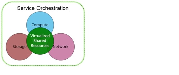
A cloud deployment model is distinctive from traditional deployments in its ability to treat the data center as a common fabric of resources available in an on-demand basis. A portion of these pools are dynamically allocated to individual tenants and then deallocated when they are no longer in use. As depicted in Figure 2-1, VMDC defines two key building blocks:
•![]() Virtualized Shared Resource Pool—The resource pool consists of network, compute, and storage components. These components are virtualized and used by multiple tenants securely.
Virtualized Shared Resource Pool—The resource pool consists of network, compute, and storage components. These components are virtualized and used by multiple tenants securely.
•![]() Service Orchestration—Service orchestration automates the resource provisioning workflow. It leverages a set of tools and APIs to dynamically provision cloud resources on demand. A tenant initiates the workflow process using a web portal to request specific resources.
Service Orchestration—Service orchestration automates the resource provisioning workflow. It leverages a set of tools and APIs to dynamically provision cloud resources on demand. A tenant initiates the workflow process using a web portal to request specific resources.
Figure 2-1 VMDC Building Blocks

Note ![]() This document addresses design aspects of the shared resource pool that a customer must understand before implementing a cloud data center. It does not address service orchestration components and design. A separate module of the VMDC 2.0 document provides service orchestration design and implementation guidance.
This document addresses design aspects of the shared resource pool that a customer must understand before implementing a cloud data center. It does not address service orchestration components and design. A separate module of the VMDC 2.0 document provides service orchestration design and implementation guidance.
When designing an IaaS architecture and the shared resources pools, network architects should consider the following design goals:
•![]() Secure Separation—Provides end-to-end tenant path isolation and security. Tenants are isolated from each other via several security techniques at different layers of the network or infrastructure. For example, virtual route forwarding instances (VRFs) are leveraged at the Layer 3 to stop communication between tenants at Layer 3 domain. Likewise, similar isolation features are leveraged at compute and storage layers to provide complete isolation of tenants in a shared infrastructure.
Secure Separation—Provides end-to-end tenant path isolation and security. Tenants are isolated from each other via several security techniques at different layers of the network or infrastructure. For example, virtual route forwarding instances (VRFs) are leveraged at the Layer 3 to stop communication between tenants at Layer 3 domain. Likewise, similar isolation features are leveraged at compute and storage layers to provide complete isolation of tenants in a shared infrastructure.
•![]() Data Center Scalability—A pod-based architecture provides network architects the ability to modularize the infrastructure into easily replicable units called pods. Architects can plan for an initial pod, which guarantees a certain scale and performance along with a scalable data center core network. This architecture provides a predictable and homogeneous method for adding self-contained pods as additional resources are needed.
Data Center Scalability—A pod-based architecture provides network architects the ability to modularize the infrastructure into easily replicable units called pods. Architects can plan for an initial pod, which guarantees a certain scale and performance along with a scalable data center core network. This architecture provides a predictable and homogeneous method for adding self-contained pods as additional resources are needed.
•![]() High Availability—Availability ensures that the cloud resources are accessible even during a failure situation. Availability is required to meet the expectations of service-level agreements (SLAs) in a cloud deployment.
High Availability—Availability ensures that the cloud resources are accessible even during a failure situation. Availability is required to meet the expectations of service-level agreements (SLAs) in a cloud deployment.
•![]() Service Assurance—Provides mechanisms to define different service levels and defines how to adhere to them using network QoS techniques during both steady and non-steady states. To differentiate IaaS service tiers, network architects can reserve and guarantee certain network bandwidths based on their subscription rules for the tier. For example, a Gold tenant could be guaranteed with 1 Gbs of bandwidth per VM whereas a Silver tenant only gets 0.5 Gbs per VM.
Service Assurance—Provides mechanisms to define different service levels and defines how to adhere to them using network QoS techniques during both steady and non-steady states. To differentiate IaaS service tiers, network architects can reserve and guarantee certain network bandwidths based on their subscription rules for the tier. For example, a Gold tenant could be guaranteed with 1 Gbs of bandwidth per VM whereas a Silver tenant only gets 0.5 Gbs per VM.
Table 2-1 presents example storage distinctions by service tier.
End-to-End Topologies
Figure 2-2 shows the end-to-end logical topology for Gold, Silver, and Bronze service classes.
Figure 2-2 End-to-End Logical Topology (Gold, Silver, Bronze)
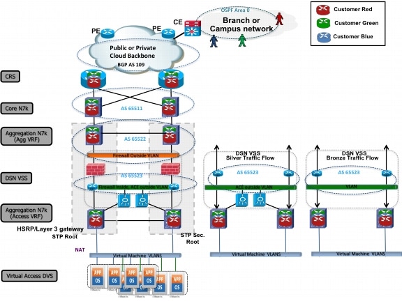
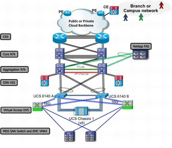
Figure 2-3 the end-to-end physical topology.
Figure 2-3 End-to-End Physical Topology (Gold, Silver, Bronze)
 Feedback