Secure Firewall Management Center and Threat Defense Management Network Administration
This document describes the management connection between the Cisco Secure Firewall Management Center and the Secure Firewall Threat Defense, management network basics, and how to change network settings, including changing the IP address of the threat defense or the management center, or both.
About the Management Center and Device Management
When the management center manages a device, it sets up a two-way, SSL-encrypted communication channel between itself and the device. The management center uses this channel to send information to the device about how you want to analyze and manage your network traffic to the device. As the device evaluates the traffic, it generates events and sends them to the management center using the same channel.
By using the management center to manage devices, you can:
-
configure policies for all your devices from a single location, making it easier to change configurations
-
install various types of software updates on devices
-
push health policies to your managed devices and monitor their health status from the management center
 Note |
If you have a CDO-managed device and are using the on-prem management center for analytics only, then the on-prem management center does not support policy configuration or upgrading. Chapters and procedures in this guide related to device configuration and other unsupported features do not apply to devices whose primary manager is CDO. |
The management center aggregates and correlates intrusion events, network discovery information, and device performance data, allowing you to monitor the information that your devices are reporting in relation to one another, and to assess the overall activity occurring on your network.
You can use the management center to manage nearly every aspect of a device’s behavior.
Note |
Although the management center can manage devices running certain previous releases as specified in the compatibility matrix available at http://www.cisco.com/c/en/us/support/security/defense-center/products-device-support-tables-list.html, new features that require the latest version of threat defense software are not available to these previous-release devices. Some management center features may be available for earlier versions. |
About Device Management Interfaces
Each device includes a single dedicated Management interface for communicating with the management center. You can optionally configure the device to use a data interface for management instead of the dedicated Management interface.
You can perform initial setup on the management interface, or on the console port.
Management interfaces are also used to communicate with the Smart Licensing server, to download updates, and to perform other management functions.
About the Management Connection
After you configure the device with the management center information and after you add the device to the management center, either the device or the management center can establish the management connection. Depending on initial setup:
-
Either the device or the management center can initiate.
-
Only the device can initiate.
-
Only the management center can initiate.
Initiation always originates with eth0 on the management center or with the lowest-numbered management interface on the device. Additional management interfaces are tried if the connection is not established. Multiple management interfaces on the management center let you connect to discrete networks or to segregate management and event traffic. However, the initiator does not choose the best interface based on the routing table.
Note |
The management connection is a secure, TLS-1.3-encrypted communication channel between itself and the device. You do not need to run this traffic over an additional encrypted tunnel such as Site-to-Site VPN for security purposes. If the VPN goes down, for example, you will lose your management connection, so we recommend a simple management path. |
Management Interfaces on the Management Center
The management center uses the eth0 interface for initial setup, HTTP access for administrators, management of devices, as well as other management functions such as licensing and updates.
You can also configure additional management interfaces. When the management center manages large numbers of devices on different networks, adding more management interfaces can improve throughput and performance. You can also use these interfaces for all other management functions. You might want to use each management interface for particular functions; for example, you might want to use one interface for HTTP administrator access and another for device management.
For device management, the management interface carries two separate traffic channels: the management traffic channel carries all internal traffic (such as inter-device traffic specific to managing the device), and the event traffic channel carries all event traffic (such as web events). You can optionally configure a separate event-only interface on the management center to handle event traffic; you can configure only one event interface. You must also always have a management interface for the management traffic channel. Event traffic can use a large amount of bandwidth, so separating event traffic from management traffic can improve the performance of the management center. For example, you can assign a 10 GigabitEthernet interface to be the event interface, if available, while using 1 GigabitEthernet interfaces for management. You might want to configure an event-only interface on a completely secure, private network while using the regular management interface on a network that includes Internet access, for example. Though you may use both management and event interfaces on the same network, we recommend that placing each interface on a separate network to avoid potential routing problems, including routing problems from other devices to the management center. Managed devices will send management traffic to the management center's management interface and event traffic to the management center's event-only interface. If the managed device cannot reach the event-only interface, then it will fall back to sending events to the management interface. However, the management connections cannot be made through the event-only interface.
Management connection initiation from the management center is always attempted first from eth0 and then other interfaces are tried in order; the routing table is not used to determine the best interface.
Note |
All management interfaces support HTTP administrator access as controlled by your Access List configuration. Conversely, you cannot restrict an interface to only HTTP access; management interfaces always support device management (management traffic, event traffic, or both). |
Note |
Only the eth0 interface supports DHCP IP addressing. Other management interfaces only support static IP addresses. |
Management and Event Interfaces on the Threat Defense
When you set up your device, you specify the management center IP address or hostname that you want to connect to, if known. In this case, the device initiates the connection, and both management and event traffic go to this address at initial registration. If the management center is not known, then the management center establishes the initial connection. In this case, it might initially connect from a different management center management interface than specified on the threat defense. Subsequent connections should use the management center management interface with the specified IP address.
If the management center has a separate event-only interface, the managed device sends subsequent event traffic to the management center event-only interface if the network allows. In addition, some managed-device models include an additional management interface that you can configure for event-only traffic. Note that if you configure a data interface for management, you cannot use separate management and event interfaces. If the event network goes down, then event traffic reverts to the regular management interfaces on the management center and/or on the managed device.
Using the Threat Defense Data Interface for Management
You can use either the dedicated Management interface or a regular data interface for communication with the management center. Manager access on a data interface is useful if you want to manage the threat defense remotely from the outside interface, or you do not have a separate management network. Moreover, using a data interface lets you configure a redundant secondary interface to take over management functions if the primary interface goes down.
Manager Access Requirements
Manager access from a data interface has the following requirements.
-
You can only enable manager access on a physical, data interface. You cannot use a subinterface or EtherChannel. You can also use the management center to enable manager access on a single secondary interface for redundancy.
-
This interface cannot be management-only.
-
Routed firewall mode only, using a routed interface.
-
PPPoE is not supported. If your ISP requires PPPoE, you will have to put a router with PPPoE support between the threat defense and the WAN modem.
-
The interface must be in the global VRF only.
-
SSH is not enabled by default for data interfaces, so you will have to enable SSH later using the management center. Because the Management interface gateway will be changed to be the data interfaces, you also cannot SSH to the Management interface from a remote network unless you add a static route for the Management interface using the configure network static-routes command. For threat defense virtual on Amazon Web Services, a console port is not available, so you should maintain your SSH access to the Management interface: add a static route for Management before you continue with your configuration. Alternatively, be sure to finish all CLI configuration (including the configure manager add command) before you configure the data interface for manager access and you are disconnected.
-
You cannot use separate management and event-only interfaces.
-
Clustering is not supported. You must use the Management interface in this case.
High Availability Requirements
When using a data interface with device high availability, see the following requirements.
-
Use the same data interface on both devices for manager access.
-
Redundant manager access data interface is not supported.
-
You cannot use DHCP; only a static IP address is supported. Features that rely on DHCP cannot be used, including DDNS and low-touch provisioning.
-
Have different static IP addresses in the same subnet.
-
Use either IPv4 or IPv6; you cannot set both.
-
Use the same manager configuration (configure manager add command) to ensure that the connectivity is the same.
-
You cannot use the data interface as the failover or state link.
Management Interface Support Per Management Center Model
See the hardware installation guide for your model for the management interface locations.
See the following table for supported management interfaces on each management center model.
|
Model |
Management Interfaces |
|---|---|
|
MC1600, MC2600, MC4600 |
eth0 (Default) eth1 eth2 eth3 CIMC (Supported for Lights-Out Management only.) |
|
Management Center Virtual |
eth0 (Default) |
Management Interface Support Per Device Model
See the hardware installation guide for your model for the management interface locations.
Note |
For the Firepower 4100/9300, the MGMT interface is for chassis management, not for threat defense logical device management. You must configure a separate interface to be of type mgmt (and/or firepower-eventing), and then assign it to the threat defense logical device. |
See the following table for supported management interfaces on each managed device model.
|
Model |
Management Interface |
Optional Event Interface |
||||
|---|---|---|---|---|---|---|
|
Firepower 1000 |
management0
|
No Support |
||||
|
Firepower 2100 |
management0
|
No Support |
||||
|
Secure Firewall 3100 |
management0
|
No Support |
||||
|
Secure Firewall 4200 |
management0
|
management1
|
||||
|
Firepower 4100 and 9300 |
management0
|
management1
|
||||
|
ISA 3000 |
br1
|
No support |
||||
|
Secure Firewall Threat Defense Virtual |
eth0 |
No support |
Network Routes on Management Center Management Interfaces
Management interfaces (including event-only interfaces) support only static routes to reach remote networks. When you set up your management center, the setup process creates a default route to the gateway IP address that you specify. You cannot delete this route; you can only modify the gateway address.
You can configure multiple management interfaces on some platforms. The default route does not include an egress interface, so the interface chosen depends on the gateway address you specify, and which interface's network the gateway belongs to. In the case of multiple interfaces on the default network, the device uses the lower-numbered interface as the egress interface.
At least one static route is recommended per management interface to access remote networks. We recommend placing each interface on a separate network to avoid potential routing problems, including routing problems from other devices to the management center.
Note |
The interface used for management connections is not determined by the routing table. Connections are always tried using eth0 first, and then subsequent interfaces are tried in order until the managed device is reached. |
Network Routes on Device Management Interfaces
Management interfaces (including event-only interfaces) support only static routes to reach remote networks. When you set up your managed device, the setup process creates a default route to the gateway IP address that you specify. You cannot delete this route; you can only modify the gateway address.
Note |
The routing for management interfaces is completely separate from routing that you configure for data interfaces. If you configure a data interface for management instead of using the dedicated Management interface, traffic is routed over the backplane to use the data routing table. The information in this section does not apply. |
You can configure multiple management interfaces on some platforms (a management interface and an event-only interface). The default route does not include an egress interface, so the interface chosen depends on the gateway address you specify, and which interface's network the gateway belongs to. In the case of multiple interfaces on the default network, the device uses the lower-numbered interface as the egress interface.
At least one static route is recommended per management interface to access remote networks. We recommend placing each interface on a separate network to avoid potential routing problems, including routing problems from other devices to the threat defense.
Note |
The interface used for management connections is not determined by the routing table. Connections are always tried using the lowest-numbered interface first. |
NAT Environments
Network address translation (NAT) is a method of transmitting and receiving network traffic through a router that involves reassigning the source or destination IP address. The most common use for NAT is to allow private networks to communicate with the internet. Static NAT performs a 1:1 translation, which does not pose a problem for management center communication with devices, but port address translation (PAT) is more common. PAT lets you use a single public IP address and unique ports to access the public network; these ports are dynamically assigned as needed, so you cannot initiate a connection to a device behind a PAT router.
Normally, you need both IP addresses (along with a registration key) for both routing purposes and for authentication: the management center specifies the device IP address when you add a device, and the device specifies the management center IP address. However, if you only know one of the IP addresses, which is the minimum requirement for routing purposes, then you must also specify a unique NAT ID on both sides of the connection to establish trust for the initial communication and to look up the correct registration key. The management center and device use the registration key and NAT ID (instead of IP addresses) to authenticate and authorize for initial registration.
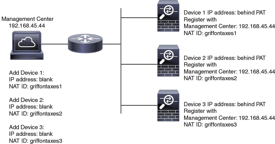
For example, you add a device to the management center, and you do not know the device IP address (for example, the device is behind a PAT router), so you specify only the NAT ID and the registration key on the management center; leave the IP address blank. On the device, you specify the management center IP address, the same NAT ID, and the same registration key. The device registers to the management center's IP address. At this point, the management center uses the NAT ID instead of IP address to authenticate the device.
Although the use of a NAT ID is most common for NAT environments, you might choose to use the NAT ID to simplify adding many devices to the management center. On the management center, specify a unique NAT ID for each device you want to add while leaving the IP address blank, and then on each device, specify both the management center IP address and the NAT ID. Note: The NAT ID must be unique per device.
The following example shows three devices behind a PAT IP address. In this case, specify a unique NAT ID per device on both the management center and the devices, and specify the management center IP address on the devices.
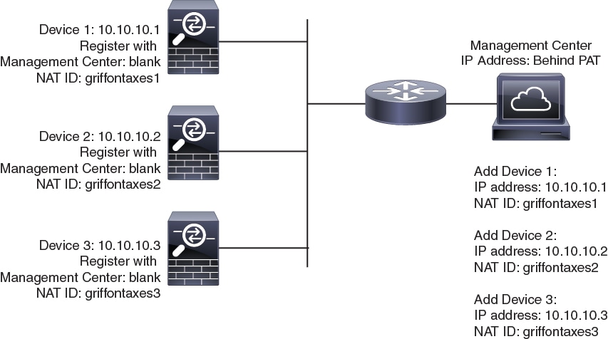
The following example shows the management center behind a PAT IP address. In this case, specify a unique NAT ID per device on both the management center and the devices, and specify the device IP addresses on the management center.
Management and Event Traffic Channel Examples
Note |
If you use a data interface for management on a threat defense, you cannot use separate management and event interfaces for that device. |
The following example shows the management center and managed devices using only the default management interfaces.
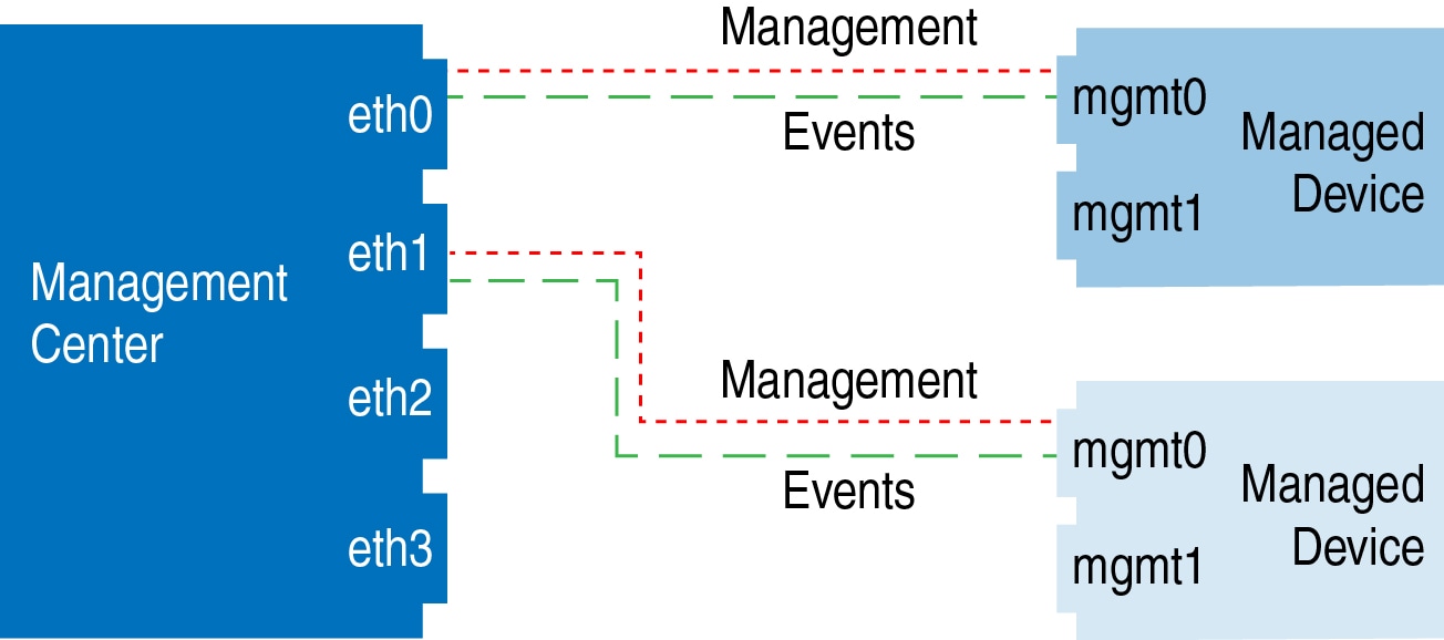
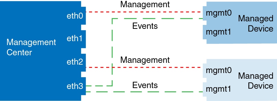
The following example shows the management center using separate management interfaces for devices; and each managed device using 1 management interface.
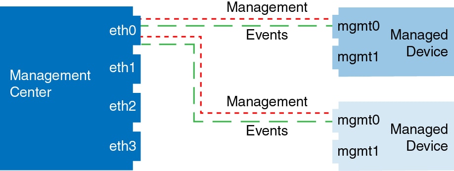
The following example shows the management center and managed devices using a separate event interface.
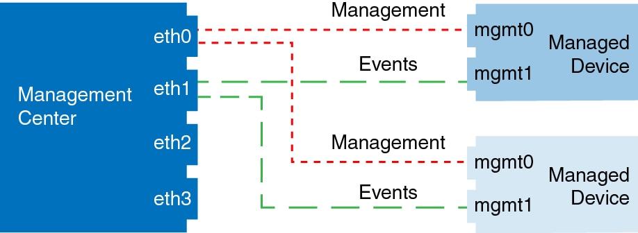
The following example shows a mix of multiple management interfaces and a separate event interface on the management center and a mix of managed devices using a separate event interface, or using a single management interface.
Complete the Threat Defense Initial Configuration for Manual Registration
You can complete the threat defense initial configuration using the CLI or the device manager for all models except for the Firepower 4100/9300. For the Firepower 4100/9300, you complete initial configuration when you deploy the logical device.
For low-touch provisioning (serial number registration), you should not log into the device or perform initial setup. See Add a Device to the Management Center Using Low-Touch Provisioning.
Complete the Threat Defense Initial Configuration Using the Device Manager
Connect to the device manager to perform initial setup of the threat defense. When you perform initial setup using the device manager, all interface configuration completed in the device manager is retained when you switch to the management center for management, in addition to the Management interface and manager access settings. Note that other default configuration settings, such as the access control policy or security zones, are not retained. When you use the CLI, only the Management interface and manager access settings are retained (for example, the default inside interface configuration is not retained).
-
The Secure Firewall 4200 does not support the device manager. You need to use the CLI procedure: Complete the Threat Defense Initial Configuration Using the CLI.
-
This procedure does not apply for CDO-managed devices for which you want to use an on-prem management center for analytics only. The device manager configuration is meant to configure the primary manager. See Complete the Threat Defense Initial Configuration Using the CLI for more information about configuring the device for analytics.
-
This procedure applies to all other devices except for the Firepower 4100/9300 and the ISA 3000. You can use the device manager to onboard these devices to the management center, but because they have different default configurations than other platforms, the details in this procedure may not apply to these platforms.
Procedure
|
Step 1 |
Log into the device manager. |
|
Step 2 |
Use the setup wizard when you first log into the device manager to complete the initial configuration. You can optionally skip the setup wizard by clicking Skip device setup at the bottom of the page. After you complete the setup wizard, in addition to the default configuration for the inside interface, you will have configuration for an outside (Ethernet1/1) interface that will be maintained when you switch to the management center management. |
|
Step 3 |
(Might be required) Configure the Management interface. You may need to change the Management interface configuration, even if you intend to use a data interface for manager access. You will have to reconnect to the device manager if you were using the Management interface for the device manager connection.
|
|
Step 4 |
If you want to configure additional interfaces, including an interface other than outside or inside that you want to use for manager access, choose Device, and then click the link in the Interfaces summary. Other device manager configuration will not be retained when you register the device to management center. |
|
Step 5 |
Choose , and click Proceed to set up the management center management. |
|
Step 6 |
Configure the Management Center/CDO Details. 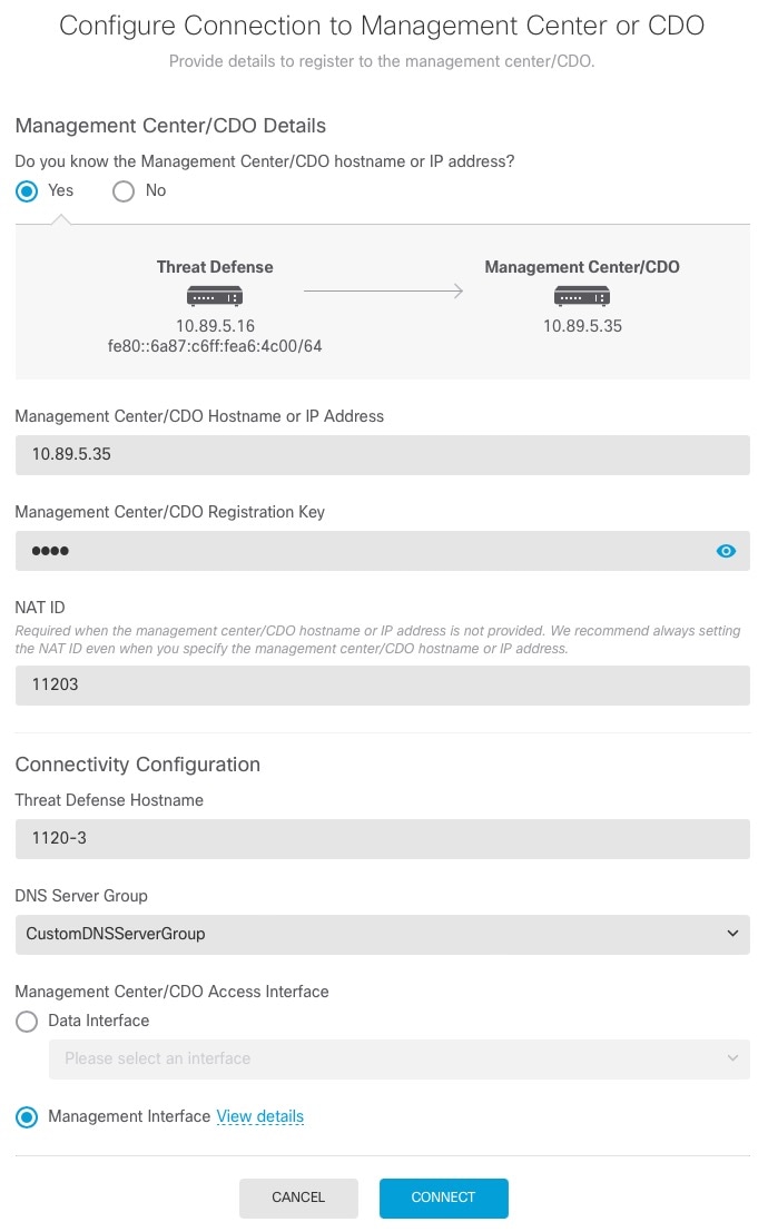
|
|
Step 7 |
Configure the Connectivity Configuration. |
|
Step 8 |
(Optional) If you chose a data interface, and it was not the outside interface, then add a default route. You will see a message telling you to check that you have a default route through the interface. If you chose outside, you already configured this route as part of the setup wizard. If you chose a different interface, then you need to manually configure a default route before you connect to the management center. If you chose the Management interface, then you need to configure the gateway to be a unique gateway before you can proceed on this screen. |
|
Step 9 |
(Optional) If you chose a data interface, click Add a Dynamic DNS (DDNS) method. DDNS ensures the management center can reach the threat defense device at its Fully-Qualified Domain Name (FQDN) if the IP address changes. See to configure DDNS. If you configure DDNS before you add the threat defense device to the management center, the threat defense device automatically adds certificates for all of the major CAs from the Cisco Trusted Root CA bundle so that the threat defense device can validate the DDNS server certificate for the HTTPS connection. Threat Defense supports any DDNS server that uses the DynDNS Remote API specification (https://help.dyn.com/remote-access-api/). DDNS is not supported when using the Management interface for manager access. |
|
Step 10 |
Click Connect. The Registration Status dialog box shows the current status of the switch to the management center. After the Saving Management Center/CDO Registration Settings step, go to the management center, and add the firewall. If you want to cancel the switch to the management center, click Cancel Registration. Otherwise, do not close the device manager browser window until after the Saving Management Center/CDO Registration Settings step. If you do, the process will be paused, and will only resume when you reconnect to the device manager. If you remain connected to the device manager after the Saving Management Center/CDO Registration Settings step, you will eventually see the Successful Connection with Management Center or CDO dialog box, after which you will be disconnected from the device manager. 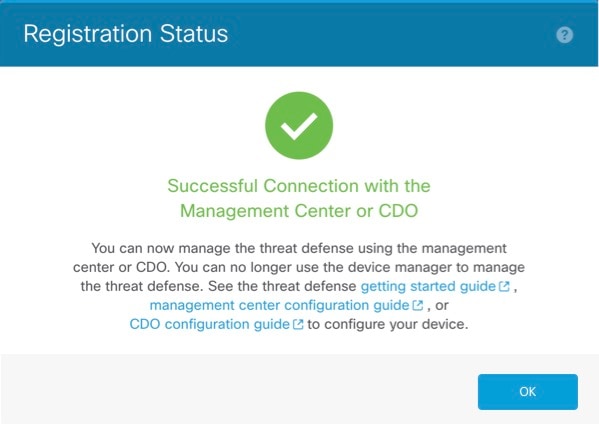
|
Complete the Threat Defense Initial Configuration Using the CLI
Connect to the threat defense CLI to perform initial setup, including setting the Management IP address, gateway, and other basic networking settings using the setup wizard. The dedicated Management interface is a special interface with its own network settings. If you do not want to use the Management interface for manager access, you can use the CLI to configure a data interface instead. You will also configure management center communication settings. When you perform initial setup using the device manager, all interface configuration completed in the device manager is retained when you switch to the management center for management, in addition to the Management interface and manager access interface settings. Note that other default configuration settings, such as the access control policy, are not retained.
Before you begin
This procedure applies to all models except for the Firepower 4100/9300.
Procedure
|
Step 1 |
Connect to the threat defense CLI, either from the console port or using SSH to the Management interface, which obtains an IP address from a DHCP server by default. If you intend to change the network settings, we recommend using the console port so you do not get disconnected. (Firepower and Secure Firewall hardware models) The console port connects to the FXOS CLI. The SSH session connects directly to the threat defense CLI. |
||||
|
Step 2 |
Log in with the username admin and the password Admin123. (Firepower and Secure Firewall hardware models) At the console port, you connect to the FXOS CLI. The first time you log in to FXOS, you are prompted to change the password. This password is also used for the threat defense login for SSH.
Example: |
||||
|
Step 3 |
(Firepower and Secure Firewall hardware models) If you connected to FXOS on the console port, connect to the threat defense CLI. connect ftd Example: |
||||
|
Step 4 |
The first time you log in to the threat defense, you are prompted to accept the End User License Agreement (EULA) and, if using an SSH connection, to change the admin password. You are then presented with the CLI setup script.
Defaults or previously entered values appear in brackets. To accept previously entered values, press Enter.
See the following guidelines:
Example: |
||||
|
Step 5 |
Identify the management center that will manage this threat defense. configure manager add {hostname | IPv4_address | IPv6_address | DONTRESOLVE} reg_key [nat_id] [display_name]
Example:Example:If the management center is behind a NAT device, enter a unique NAT ID along with the registration key, and specify DONTRESOLVE instead of the hostname, for example: Example:If the threat defense is behind a NAT device, enter a unique NAT ID along with the management center IP address or hostname, for example: |
||||
|
Step 6 |
If you are using CDO as your primary manager and want to use an on-prem management center for analytics only, identify the on-prem management center. configure manager add {hostname | IPv4_address | IPv6_address | DONTRESOLVE} reg_key [nat_id] [display_name] Example:The following example uses the generated command for CDO with an added display name of "CDO," and then specifies an on-prem management center for analytics only. |
||||
|
Step 7 |
(Optional) Configure a data interface for manager access. configure network management-data-interface You are then prompted to configure basic network settings for the data interface.
See the following details for using this command. See also Using the Threat Defense Data Interface for Management.
Example:Example: |
||||
|
Step 8 |
(Optional) Limit data interface access to a manager on a specific network. configure network management-data-interface client ip_address netmask By default, all networks are allowed. |
What to do next
Register your device to a management center.
Configure an Event Interface
You always need a management interface for management traffic. If your device has a second management interface, for example, the Firepower 4100/9300 and Secure Firewall 4200, you can enable it for event-only traffic.
Before you begin
To use a separate event interface, you also need to enable an event interface on the management center. See the Cisco Secure Firewall Management Center Administration Guide.
Procedure
|
Step 1 |
Enable the second management interface as an event-only interface. configure network management-interface enable management1 configure network management-interface disable-management-channel management1 You can optionally disable events for the main management interface using the configure network management-interface disable-events-channel command. In either case, the device will try to send events on the event-only interface, and if that interface is down, it will send events on the management interface even if you disable the event channel. You cannot disable both event and management channels on an interface. Example: |
|
Step 2 |
Configure the IP address of the event interface. The event interface can be on a separate network from the management interface, or on the same network. |
|
Step 3 |
Add a static route for the event-only interface if the management center is on a remote network; otherwise, all traffic will match the default route through the management interface. configure network static-routes {ipv4 | ipv6}add management1 destination_ip netmask_or_prefix gateway_ip For the default route, do not use this command; you can only change the default route gateway IP address when you use the configure network ipv4 or ipv6 commands (see, Step 2). Example:To display static routes, enter show network-static-routes (the default route is not shown): |
Add a Device to the Management Center Using a Registration Key
Use this procedure to add a single device to the management center using a registration key. If you plan to link devices for high availability, you must still use this procedure. For clustering, see the clustering chapter for your model.
You can also use this procedure to add a device that is managed by a cloud-delivered management center delivered by CDO, and you want to use the on-prem management center for event logging and analytics purposes only.
Note |
If you have established or will establish management center high availability, add devices only to the active (or intended active) management center. When you establish high availability, devices registered to the active management center are automatically registered to the standby. |
Before you begin
-
Set up the device to be managed by the management center. See:
-
Complete the Threat Defense Initial Configuration for Manual Registration
-
The getting started guide for your model
-
-
The management center must be registered to the Smart Software Manager. A valid evaluation license is sufficient, but if it expires, you will not be able to add new devices until you successfully register.
-
If you registered a device using IPv4 and want to convert it to IPv6, you must delete and reregister the device.
Procedure
|
Step 1 |
Choose . |
||
|
Step 2 |
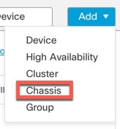
From the Add drop-down menu, choose Device. 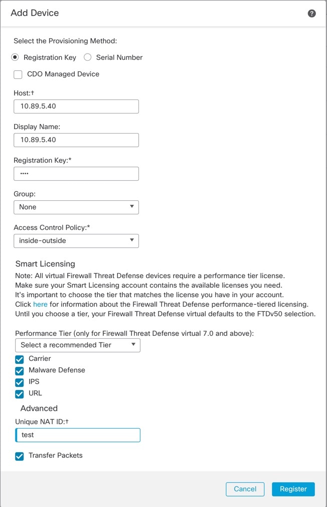
|
||
|
Step 3 |
If you want to add a CDO-managed device to your on-prem management center for analytics only, check CDO Managed Device The system hides licensing and packet transfer settings because they are managed by CDO. You can skip those steps. 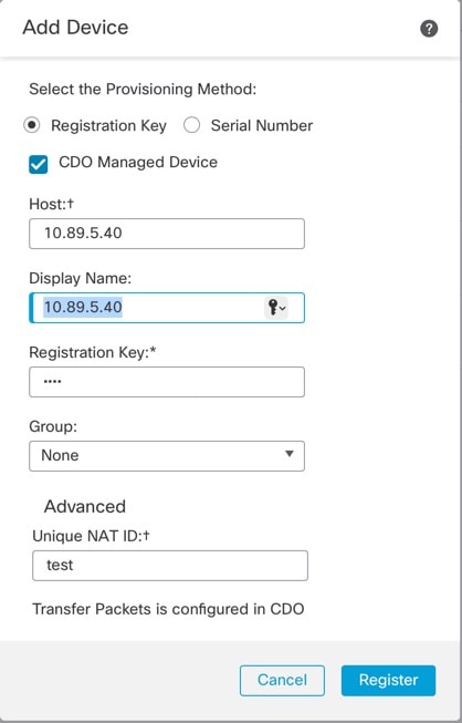
|
||
|
Step 4 |
In the Host field, enter the IP address or the hostname of the device you want to add. The hostname of the device is the fully qualified domain name or the name that resolves through the local DNS to a valid IP address. Use a hostname rather than an IP address if your network uses DHCP to assign IP addresses. In a NAT environment, you may not need to specify the IP address or hostname of the device, if you already specified the IP address or hostname of the management center when you configured the device to be managed by the management center. For more information, see NAT Environments.
|
||
|
Step 5 |
In the Display Name field, enter a name for the device as you want it to display in the management center. |
||
|
Step 6 |
In the Registration Key field, enter the same registration key that you used when you configured the device to be managed by the management center. The registration key is a one-time-use shared secret. The key can include alphanumeric characters and hyphens (-). |
||
|
Step 7 |
In a multidomain deployment, regardless of your current domain, assign the device to a leaf Domain. If your current domain is a leaf domain, the device is automatically added to the current domain. If your current domain is not a leaf domain, post-registration, you must switch to the leaf domain to configure the device. A device can only belong to one domain. |
||
|
Step 8 |
(Optional) Add the device to a device Group. |
||
|
Step 9 |
Choose an initial Access Control Policy to deploy to the device upon registration, or create a new policy. If the device is incompatible with the policy you choose, deploying will fail. This incompatibility could occur for multiple reasons, including licensing mismatches, model restrictions, passive vs inline issues, and other misconfigurations. After you resolve the issue that caused the failure, manually deploy configurations to the device. |
||
|
Step 10 |
Choose licenses to apply to the device. You can also apply licenses after you add the device, from the page. For the threat defense virtual only, you must also select the Performance Tier. It’s important to choose the tier that matches the license you have in your account. Until you choose a tier, your device defaults to the FTDv50 selection. For more information about the performance-tiered license entitlements available for threat defense virtual, see .
|
||
|
Step 11 |
If you used a NAT ID during device setup, in the Advanced section enter the same NAT ID in the Unique NAT ID field. The Unique NAT ID specifies a unique, one-time string of your choice that you will also specify on the threat defense during initial setup when one side does not specify a reachable IP address or hostname. For example, it is required if you left the Host field blank. It is also required if you use the threat defense data interface for management, even if you specify IP addresses. The NAT ID must not exceed 37 characters. Valid characters include alphanumerical characters (A–Z, a–z, 0–9) and the hyphen (-). This ID cannot be used for any other devices registering to the management center.
|
||
|
Step 12 |
Check the Transfer Packets check box to allow the device to transfer packets to the management center. This option is enabled by default. When events like IPS or Snort are triggered with this option enabled, the device sends event metadata information and packet data to the management center for inspection. If you disable it, only event information will be sent to the management center but packet data is not sent. |
||
|
Step 13 |
Click Register. It may take up to two minutes for the management center to verify the device’s heartbeat and establish communication. If the registration succeeds, the device is added to the list. If it fails, you will see an error message. If the device fails to register, check the following items:
For more troubleshooting information, see https://cisco.com/go/fmc-reg-error. |
Add a Device to the Management Center Using Low-Touch Provisioning
Low-touch provisioning lets you register devices to the management center by serial number without having to perform any initial setup on the device. The management center integrates with Cisco Defense Orchestrator (CDO) and SecureX for this functionality.
Use this procedure to add a single device to the management center. High availability is only supported when you use the Management interface, because DHCP is not supported for data interfaces and high availability. Clustering is not supported.
Note |
If the management center is configured for high availability, CDO automatically onboards the threat defense to the primary management center. |
Low-touch provisioning is only supported on the following models:
-
Firepower 1000
-
Firepower 2100
-
Secure Firewall 3100
Threat Defense Feature History:
-
7.2.4/7.4.1 (7.3 does not include this enhancement)—Outside and Management interface support. For the outside interface, the management center does not have to be publicly reachable if the device outside interface is reachable.
-
7.2, 7.3—Outside interface support only. The management center must be publicly reachable.
Before you begin
-
Make sure the device is unconfigured or a fresh install. Low-touch provisioning is meant for new devices only. Pre-configuration can disable low-touch provisioning, depending on your settings.
-
Cable the outside interface or Management interface so it can reach the internet. If you use the outside interface for low-touch provisioning, do not also cable the Management interface; if the Management interface gets an IP address from DHCP, the routing will be incorrect for the outside interface.
-
Make sure you have at least one access control policy configured on the management center so you can assign it to new devices. You cannot add a policy using CDO.
-
If the device does not have a public IP address or FQDN, or you use the Management interface, set a public IP address/FQDN for the management center (if different from the management center management interface IP address; for example, it is behind NAT) so the device can initiate the management connection. See . You can also configure the public IP address/FQDN in CDO during this procedure.
Procedure
|
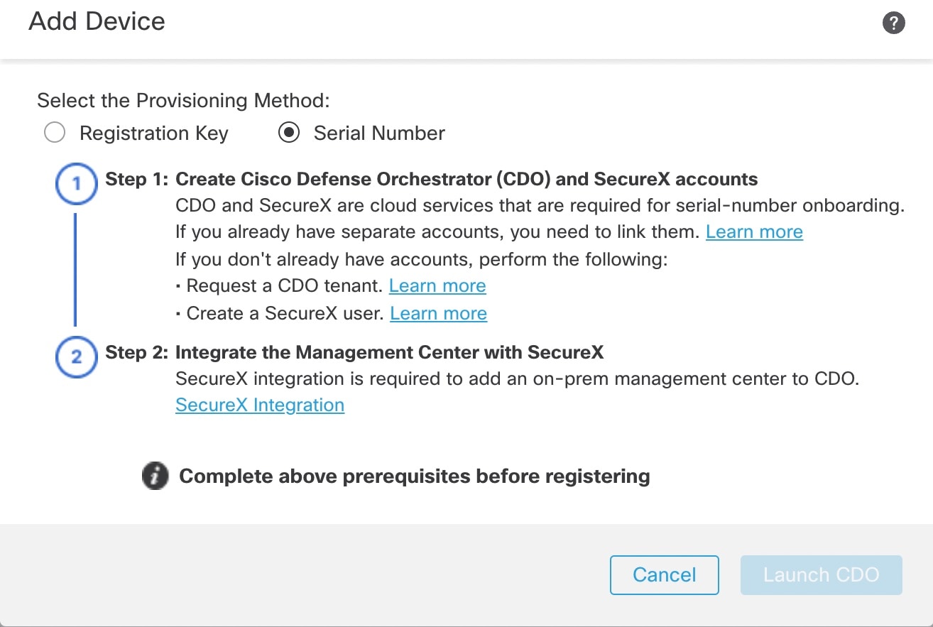
Step 1 |
The first time you add a device using a serial number, you need to complete the following prerequisites. After the first time, you can skip to adding the devices directly in CDO.
|
||
|
Step 2 |
On the CDO
Dashboard (https://www.defenseorchestrator.com/), click Onboard ( |
||
|
Step 3 |
Click the FTD tile. 
|
||
|
Step 4 |
On the Onboard FTD Device screen, click Use Serial Number. 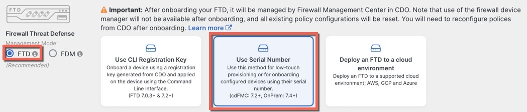
|
||
|
Step 5 |
In Select FMC, choose an On-Prem FMC from the list, and click Next. 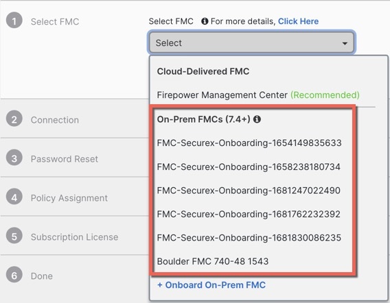
If the management center has a public IP address or FQDN set, it will show after you choose it. 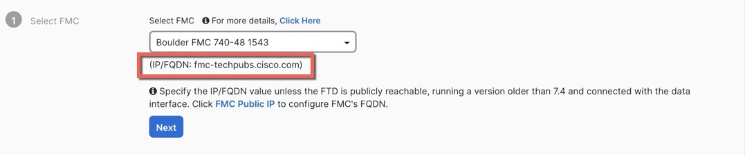
The management center needs a public IP address/FQDN if the device does not have a public IP address/FQDN or if you use the Management interface for low-touch provisioning. You can set the management center public IP address/FQDN by clicking the FMC Public IP link. You see the following dialog box. 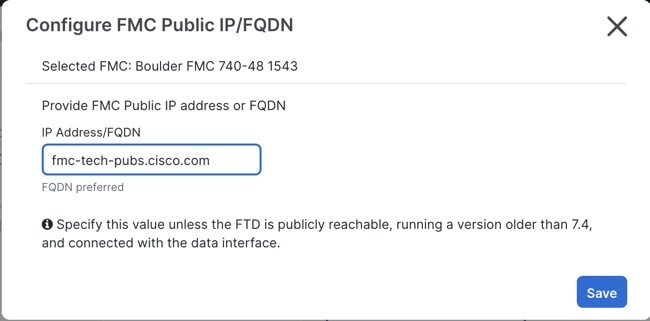
|
||
|
Step 6 |
In Connection, enter the device's serial number and device name. Click Next. 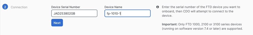
|
||
|
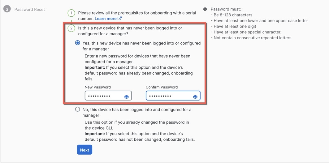
Step 7 |
In Password Reset, click Yes.... Enter a new password and confirm the new password for the device, then click Next. For low-touch provisioning, the device must be brand new or has been reimaged.
|
||
|
Step 8 |
In Policy Assignment, use the drop-down menu to select an access control policy for the device. If you have not added a policy on the management center, you should go to the management center and add one now. Click Next. 
|
||
|
Step 9 |
In Subscription License, select the licenses for the device. Click Next. 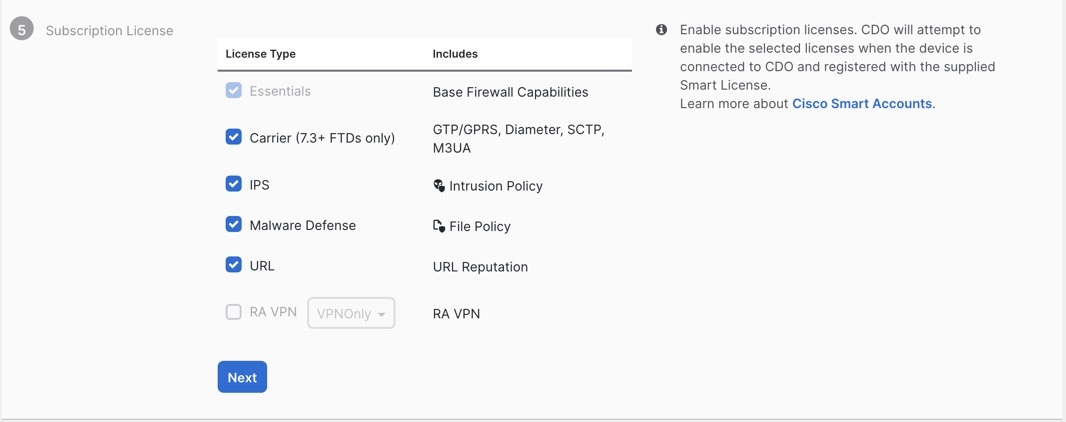
|
||
|
Step 10 |
In Done, you can add labels to the device that show in CDO; they are not used on the management center. 
In the management center, the device is added to the Device Management page. You can also click Go to Inventory to see the devices in CDO. On-prem management center devices are viewable in CDO inventory for information purposes. When using low-touch provisioning on the outside interface, CDO acts as a DDNS provider and does the following:
If you use low-touch provisioning on the Management interface, DDNS is not supported. The management center must be publicly reachable so the device and initiate the management connection. You can continue to use CDO as the DDNS provider, or you can later change the DDNS configuration in the management center to a different method. |
 ).
).
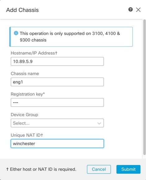
Add a Chassis to the Management Center
You can add a Firepower 4100/9300 chassis to the management center. The management center and the chassis share a separate management connection using the chassis MGMT interface. The management center offers chassis-level health alerts. For configuration, you still need to use the Secure Firewall chassis manager or FXOS CLI.
Note |
For the Secure Firewall 3100, the manager configuration is completed as part of the conversion to multi-instance mode. |
Procedure
|
Step 1 |
Connect to the chassis FXOS CLI, either using the console port or SSH. |
|
Step 2 |
Configure the management center. create device-manager manager_name [hostname {hostname | ipv4_address | ipv6_address}] [nat-id nat_id] You are prompted for the registration key. You can enter this command from any scope. This command is accepted immediately without using commit-buffer .
Example: |
|
Step 3 |
In the management center, add the chassis using the chassis management IP address or hostname.
|
Delete (Unregister) a Device from the Management Center
If you no longer want to manage a device, you can unregister it from the management center.
To unregister a cluster, cluster node, or High Availability pair, see the chapters for those deployments.
Unregistering a device:
-
Severs all communication between the management center and the device.
-
Removes the device from the Device Management page.
-
Returns the device to local time management if the device's platform settings policy is configured to receive time from the management center using NTP.
-
Leaves the configuration intact, so the device continues to process traffic.
Policies, such as NAT and VPN, ACLs, and the interface configurations remain intact.
Registering the device again to the same or a different management center causes the configuration to be removed, so the device will stop processing traffic at that point. You can choose an access control policy at registration, but you will have to re-apply other policies after registration and then deploy the configuration before it will process traffic again.
Procedure
|
Step 1 |
Choose . |
|
Step 2 |
Next to the device you want to unregister, click More ( 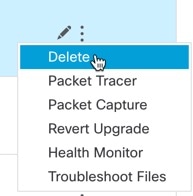
|
|
Step 3 |
Confirm that you want to unregister the device. |
|
Step 4 |
You can now change your manager.
|
 )
)Modify Management Center Management Interfaces
Modify the management interface settings on the management center. You can optionally enable additional management interfaces or configure an event-only interface.
 Caution |
Be careful when making changes to the management interface to which you are connected; if you cannot re-connect because of a configuration error, you need to access the management center console port to re-configure the network settings in the Linux shell. You must contact Cisco TAC to guide you in this operation. |
If you change the management center IP address, then see . If you change the management center IP address or hostname, you should also change the value at the device CLI so the configurations match. Although in most cases, the management connection will be reestablished without changing the management center IP address or hostname on the device, in at least one case, you must perform this task for the connection to be reestablished: when you added the device to the management center and you specified the NAT ID only. Even in other cases, we recommend keeping the management center IP address or hostname up to date for extra network resiliency.
In a high availability configuration, when you modify the management IP address of a registered device from the device CLI or from the management center, the secondary management center does not reflect the changes even after an HA synchronization. To ensure that the secondary management center is also updated, switch roles between the two management centers, making the secondary management center as the active unit. Modify the management IP address of the registered device on the Device Management page of the now active management center.
Before you begin
-
For information about how device management works, see .
-
If you use a proxy:
-
Proxies that use NT LAN Manager (NTLM) authentication are not supported.
-
If you use or will use Smart Licensing, the proxy FQDN cannot have more than 64 characters.
-
Procedure
|
Step 1 |
Choose System ( |
||||
|
Step 2 |
In the Interfaces area, click Edit next to the interface that you want to configure. All available interfaces are listed in this section. You cannot add more interfaces. You can configure the following options on each management interface:
|
||||
|
Step 3 |
In the Routes area, edit a static route by clicking Edit ( View the route table by clicking You need a static route for each additional interface to reach remote networks. For more information about when new routes are needed, see Network Routes on Management Center Management Interfaces.
You can configure the following settings for a static route:
|
||||
|
Step 4 |
In the Shared Settings area, set network parameters shared by all interfaces.
You can configure the following shared settings:
|
||||
|
Step 5 |
In the ICMPv6 area, configure ICMPv6 settings.
|
||||
|
Step 6 |
In the Proxy area, configure HTTP proxy settings. The management center is configured to directly-connect to the internet on ports TCP/443 (HTTPS) and TCP/80 (HTTP). You can use a proxy server, to which you can authenticate via HTTP Digest. See proxy requirements in the prerequisites to this topic. |
||||
|
Step 7 |
Click Save. |
||||
|
Step 8 |
If you change the management center IP address, then see If you change the management center IP address, then see . If you change the management center IP address or hostname, you should also change the value at the device CLI so the configurations match. Although in most cases, the management connection will be reestablished without changing the management center IP address or hostname on the device, in at least one case, you must perform this task for the connection to be reestablished: when you added the device to the management center and you specified the NAT ID only. Even in other cases, we recommend keeping the management center IP address or hostname up to date for extra network resiliency. |
 )
) )
) )
) .
.
Modify the Threat Defense Management Interface
Update the Hostname or IP Address in Management Center
If you edit the hostname or IP address of a device after you added it to the management center (using the device’s CLI, for example), you need to use the procedure below to manually update the hostname or IP address on the managing management center.
If you used only the NAT ID when registering the device, then the IP shows as NO-IP on this page, and you do not need to update the IP address/hostname.
If you used low-touch provisioning to register the device on the outside interface, the hostname is automatically generated along with a matching DDNS configuration; you cannot edit the hostname in this case.
Threat Defense Feature History:
-
7.3—Redundant manager access data interface
Procedure
|
Step 1 |
Choose . |
|
Step 2 |
Next to the device where you want to modify management
options, click Edit ( In a multidomain deployment, if you are not in a leaf domain, the system prompts you to switch. |
|
Step 3 |
Click Device, and view the Management area. |
|
Step 4 |
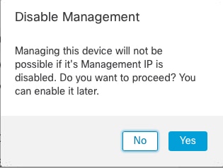
Disable management temporarily by clicking the slider so it is disabled ( 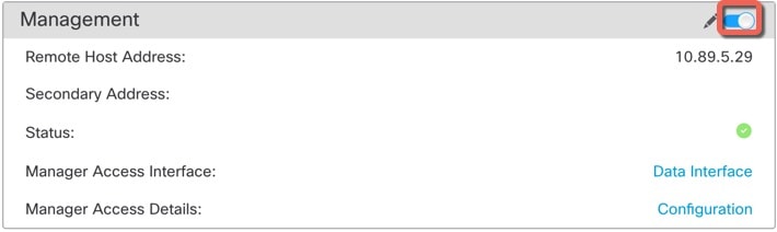
You are prompted to proceed with disabling management; click Yes.
Disabling management blocks the connection between the management center and the device, but does not delete the device from the management center. |
|
Step 5 |
Edit the Remote Host Address IP address and optional Secondary Address (when using a redundant data interface) or hostname by clicking Edit ( 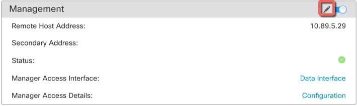
|
|
Step 6 |
In the Management dialog box, modify the name or IP address in the Remote Host Address field and the optional Secondary Address field, and click Save. For information about using a secondary manager access data interface, see Configure a Redundant Manager Access Data Interface. 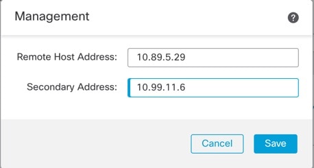
|
|
Step 7 |
Reenable management by clicking the slider so it is enabled ( 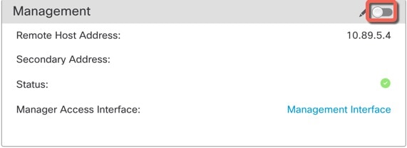
|
 )
)
 )
)Change the Manager Access Interface from Management to Data
You can manage the threat defense from either the dedicated Management interface, or from a data interface. If you want to change the manager access interface after you added the device to the management center, follow these steps to migrate from the Management interface to a data interface. To migrate the other direction, see Change the Manager Access Interface from Data to Management.
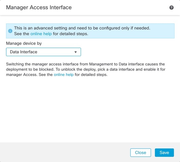
Initiating the manager access migration from Management to data causes the management center to apply a block on deployment to the threat defense. To remove the block, enable manager access on the data interface.
See the following steps to enable manager access on a data interface, and also configure other required settings.
Before you begin
For high-availability pairs, unless stated otherwise, perform all steps only on the active unit. Once the configuration changes are deployed, the standby unit synchronizes configuration and other state information from the active unit.
Procedure
|
Step 1 |
Initiate the interface migration.
|
|
Step 2 |
Enable manager access on a data interface on the page. You can enable manager access on one routed data interface, plus an optional secondary interface. Make sure these interfaces are fully configured with a name and IP address and that they are enabled. If you use a secondary interface for redundancy, see Configure a Redundant Manager Access Data Interface for additional required configuration. |
|
Step 3 |
(Optional) If you use DHCP for the interface, enable the web type DDNS method on the page. DDNS ensures the management center can reach the threat defense at its Fully-Qualified Domain Name (FQDN) if the FTD's IP address changes. |
|
Step 4 |
Make sure the threat defense can route to the management center through the data interface; add a static route if necessary on . |
|
Step 5 |
(Optional) Configure DNS in a Platform Settings policy, and apply it to this device at . DNS is required if you use DDNS. You may also use DNS for FQDNs in your security policies. |
|
Step 6 |
(Optional) Enable SSH for the data interface in a Platform Settings policy, and apply it to this device at . SSH is not enabled by default on the data interfaces, so if you want to manage the threat defense using SSH, you need to explicitly allow it. |
|
Step 7 |
Deploy configuration changes. The management center will deploy the configuration changes over the current Management interface. After the deployment, the data interface is now ready for use, but the original management connection to Management is still active. |
|
Step 8 |
At the threat defense CLI (preferably from the console port), set the Management interface to use a static IP address and set the gateway to use the data interfaces. For high availability, perform this step on both units. configure network {ipv4 | ipv6} manual ip_address netmask data-interfaces
We recommend that you use the console port instead of an SSH connection because when you change the Management interface network settings, your SSH session will be disconnected. |
|
Step 9 |
If necessary, re-cable the threat defense so it can reach the management center on the data interface. For high availability, perform this step on both units. |
|
Step 10 |
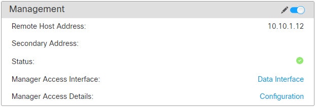
In the management center, disable the management connection, update the Remote Host Address IP address and optional Secondary Address for the threat defense in the section, and reenable the connection. See Update the Hostname or IP Address in Management Center. If you used the threat defense hostname or just the NAT ID when you added the threat defense to the management center, you do not need to update the value; however, you need to disable and reenable the management connection to restart the connection. |
|
Step 11 |
Ensure the management connection is reestablished. In the management center, check the management connection status on the page. At the threat defense CLI, enter the sftunnel-status-brief command to view the management connection status. The following status shows a successful connection for a data interface, showing the internal "tap_nlp" interface. 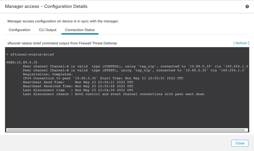
If it takes more than 10 minutes to reestablish the connection, you should troubleshoot the connection. See Troubleshoot Management Connectivity on a Data Interface. |
Change the Manager Access Interface from Data to Management
You can manage the threat defense from either the dedicated Management interface, or from a data interface. If you want to change the manager access interface after you added the device to the management center, follow these steps to migrate from a data interface to the Management interface. To migrate the other direction, see Change the Manager Access Interface from Management to Data.
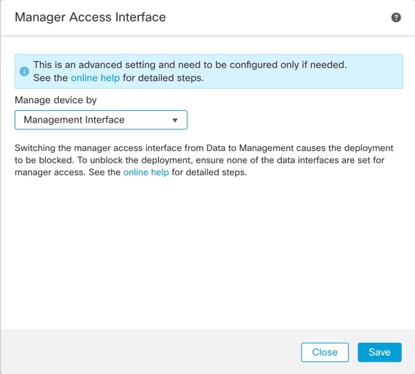
Initiating the manager access migration from data to Management causes the management center to apply a block on deployment to the threat defense. You must disable manager access on the data interface to remove the block.
See the following steps to disable manager access on a data interface, and also configure other required settings.
Before you begin
For high-availability pairs, unless stated otherwise, perform all steps only on the active unit. Once the configuration changes are deployed, the standby unit synchronizes configuration and other state information from the active unit.
Procedure
|
Step 1 |
Initiate the interface migration.
|
|
Step 2 |
Disable manager access on the data interface(s) on the page. This step removes the block on deployment. |
|
Step 3 |
If you have not already done so, configure DNS settings for the data interface in a Platform Setting policy, and apply it to this device at . The management center deployment that disables manager access on the data interface will remove any local DNS configuration. If that DNS server is used in any security policy, such as an FQDN in an Access Rule, then you must re-apply the DNS configuration using the management center. |
|
Step 4 |
Deploy configuration changes. The management center will deploy the configuration changes over the current data interface. |
|
Step 5 |
If necessary, re-cable the threat defense so it can reach the management center on the Management interface. For High Availability, perform this step on both units. |
|
Step 6 |
At the threat defense CLI, configure the Management interface IP address and gateway using a static IP address or DHCP. For high availability, perform this step on both units. When you originally configured the data interface for manager access, the Management gateway was set to data-interfaces, which forwarded management traffic over the backplane so it could be routed through the manager access data interface. You now need to set an IP address for the gateway on the management network. Static IP address: configure network {ipv4 | ipv6} manual ip_address netmask gateway_ip DHCP: configure network{ipv4 | ipv6} dhcp |
|
Step 7 |
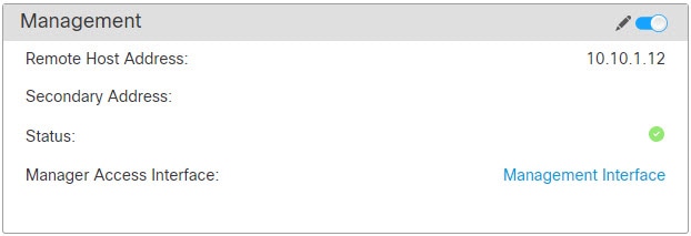
In the management center, disable the management connection, update the Remote Host Address IP address and remove the optional Secondary Address for the threat defense in the section, and reenable the connection. See Update the Hostname or IP Address in Management Center. If you used the threat defense hostname or just the NAT ID when you added the threat defense to the management center, you do not need to update the value; however, you need to disable and re-enable the management connection to restart the connection. |
|
Step 8 |
Ensure the management connection is reestablished. In the management center, check the management connection status on the field or view notifications in the management center. At the threat defense CLI, enter the sftunnel-status-brief command to view the management connection status. If it takes more than 10 minutes to reestablish the connection, you should troubleshoot the connection. See Troubleshoot Management Connectivity on a Data Interface. |
Configure a Redundant Manager Access Data Interface
When you use a data interface for manager access, you can configure a secondary data interface to take over management functions if the primary interface goes down. You can configure only one secondary interface. The device uses SLA monitoring to track the viability of the static routes and an ECMP zone that contains both interfaces so management traffic can use both interfaces.
High availability is not supported.
Before you begin
-
The secondary interface needs to be in a separate security zone from the primary interface.
-
All of the same requirements apply to the secondary interface as apply to the primary interface. See Using the Threat Defense Data Interface for Management.
Procedure
|
Step 1 |
On the page, click Edit ( |
|
Step 2 |
Enable manager access for the secondary interface. This setting is in addition to standard interface settings such as enabling the interface, setting the name, setting the security zone, and setting a static IPv4 address.
Both inetrfaces show (Manager Access) in the interface listing. 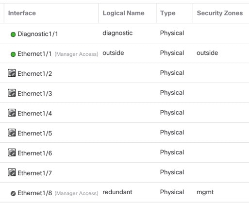
|
|
Step 3 |
Add the secondary address to the Management settings.
|
|
Step 4 |
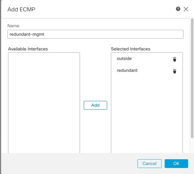
Create an ECMP zone with both interfaces.
|
|
Step 5 |
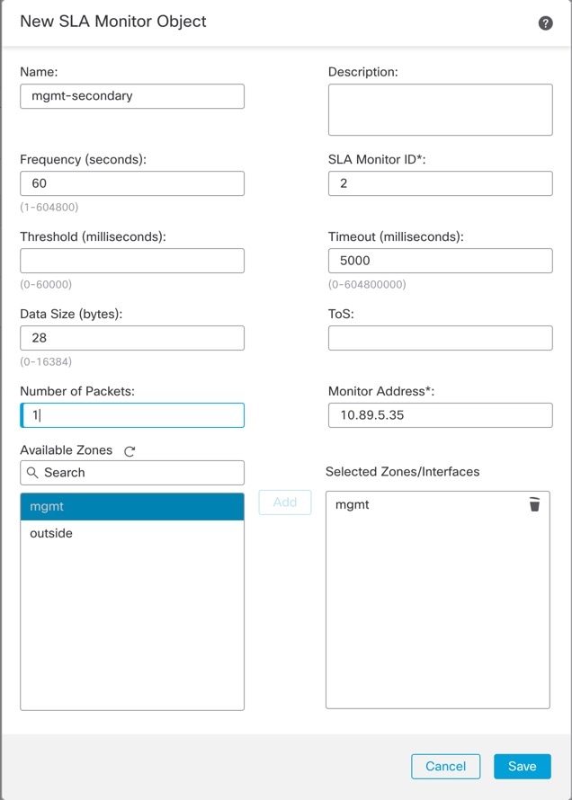
Add equal-cost default static routes for both interfaces and enable SLA tracking on both. The routes should be identical except for the gateway and should both have metric 1. The primary interface should already have a default route that you can edit. 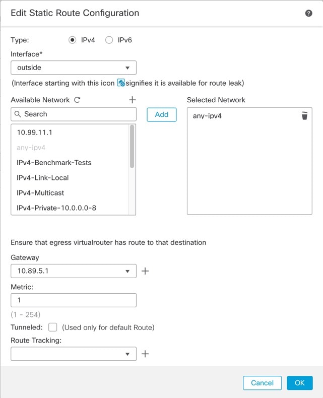
|
|
Step 6 |
Deploy configuration changes. As part of the deployment for this feature, the management center enables the secondary interface for management traffic, including auto-generated policy-based routing configuration for management traffic to get to the right data interface. The management center also deploys a second instance of the configure network management-data-interface command. Note that if you edit the secondary interface at the CLI, you cannot configure the gateway or otherwise alter the default route, because the static route for this interface can only be edited in the management center. |
View Manager Access Details for Data Interface Management
Model Support—Threat Defense
When you use a data interface for management center management instead of using the dedicated Management interface, you must be careful about changing the interface and network settings for the device in the management center so you do not disrupt the connection. You can also change the data interface settings locally on the device, which requires you to reconcile those changes in the management center manually. The dialog box helps you resolve any discrepancies between the management center and the threat defense local configuration.
Normally, you configure the manager access data interface as part of initial threat defense setup before you add the threat defense to the management center. When you add the threat defense to the management center, the management center discovers and maintains the interface configuration, including the following settings: interface name and IP address, static route to the gateway, DNS servers, and DDNS server. For the DNS server, the configuration is maintained locally if it is discovered during registration, but it is not added to the Platform Settings policy in management center.
After you add the threat defense to the management center, if you change the data interface settings on the threat defense locally using the configure network management-data-interface command, then the management center detects the configuration changes, and blocks deployment to the threat defense. The management center detects the configuration changes using one of the following methods:
-
Deploy to the threat defense. Before the management center deploys, it will detect the configuration differences and stop the deployment.
-
The Sync button in the Interfaces page.
-
The Refresh button on the Manager Access - Configuration Details dialog box.
To remove the block, you must go to the Manager Access - Configuration Details dialog box and click Acknowledge. The next time you deploy, the management center configuration will overwrite any remaining conflicting settings on the threat defense. It is your responsibility to manually fix the configuration in the management center before you re-deploy.
See the following pages on this dialog box.
Configuration
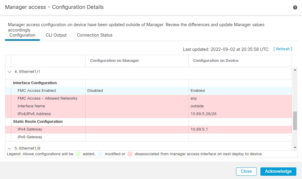
View the configuration comparison of the manager access data interface on the management center and the threat defense.
The following example shows the configuration details of the threat defense where the configure network management-data-interface command was entered on the threat defense. The pink highlights show that if you Acknowledge the differences but do not match the configuration in the management center, then the threat defense configuration will be removed. The blue highlights show configurations that will be modified on the threat defense. The green highlights show configurations that will be added to the threat defense.
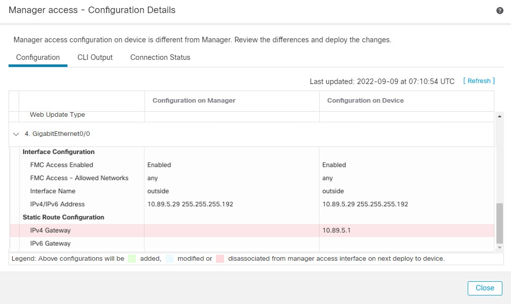
The following example shows this page after configuring the interface in the management center; the interface settings match, and the pink highlight was removed.
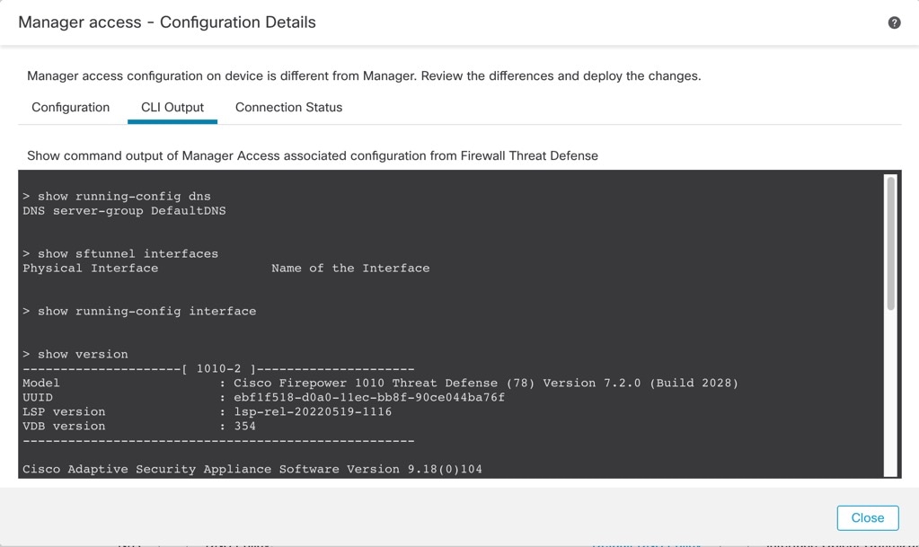
CLI Output
View the CLI configuration of the manager access data interface, which is useful if you are familiar with the underlying CLI.
Connection Status
View management connection status. The following example shows that the management connection is still using the Management "management0" interface.
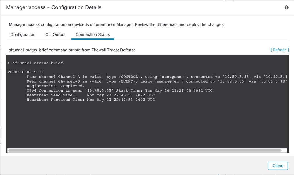
The following status shows a successful connection for a data interface, showing the internal "tap_nlp" interface.
See the following sample output for a connection that is down; there is no peer channel "connected to" information, nor heartbeat information shown:
> sftunnel-status-brief
PEER:10.10.17.202
Registration: Completed.
Connection to peer '10.10.17.202' Attempted at Mon Jun 15 09:21:57 2020 UTC
Last disconnect time : Mon Jun 15 09:19:09 2020 UTC
Last disconnect reason : Both control and event channel connections with peer went down
See the following sample output for a connection that is up, with peer channel and heartbeat information shown:
> sftunnel-status-brief
PEER:10.10.17.202
Peer channel Channel-A is valid type (CONTROL), using 'eth0', connected to '10.10.17.202' via '10.10.17.222'
Peer channel Channel-B is valid type (EVENT), using 'eth0', connected to '10.10.17.202' via '10.10.17.222'
Registration: Completed.
IPv4 Connection to peer '10.10.17.202' Start Time: Wed Jun 10 14:27:12 2020 UTC
Heartbeat Send Time: Mon Jun 15 09:02:08 2020 UTC
Heartbeat Received Time: Mon Jun 15 09:02:16 2020 UTC
Modify Threat Defense Management Interfaces at the CLI
Modify the management interface settings on the managed device using the CLI. Many of these settings are ones that you set when you performed the initial setup; this procedure lets you change those settings, and set additional settings such as enabling an event interface if your model supports it, or adding static routes.
Note |
This topic applies to the dedicated Management interface. You can alternatively configure a data interface for management. If you want to change network settings for that interface, you should do so within management center and not at the CLI. If you need to troubleshoot a disrupted management connection, and need to make changes directly on the threat defense, see Modify the Threat Defense Data Interface Used for Management at the CLI. |
For information about the threat defense CLI, see the Cisco Secure Firewall Threat Defense Command Reference.
Note |
When using SSH, be careful when making changes to the management interface; if you cannot re-connect because of a configuration error, you will need to access the device console port. |
Note |
If you change the device management IP address, then see the following tasks for management center connectivity depending on how you identified the management center during initial device setup using the configure manager add command (see Identify a New Management Center):
|
Note |
In a High Availability management center configuration, when you modify the management IP address from the device CLI or from the management center, the secondary management center does not reflect the changes even after an HA synchronization. To ensure that the secondary management center is also updated, switch roles between the two management centers, making the secondary management center the active unit. Modify the management IP address of the registered device on the device management page of the now active management center. |
Before you begin
-
You can create user accounts that can log into the CLI using the configure user add command.
Procedure
|
Step 1 |
Connect to the device CLI, either from the console port or using SSH. |
||
|
Step 2 |
Log in with the Admin username and password. |
||
|
Step 3 |
(Firepower 4100/9300/Secure Firewall 4200 only) Enable the second management interface as an event-only interface. configure network management-interface enable management1 configure network management-interface disable-management-channel management1 You always need a management interface for management traffic. If your device has a second management interface, you can enable it for event-only traffic. You can optionally disable events for the main management interface using the configure network management-interface disable-events-channel command. In either case, the device will try to send events on the event-only interface, and if that interface is down, it will send events on the management interface even if you disable the event channel. You cannot disable both event and management channels on an interface. To use a separate event interface, you also need to enable an event interface on the management center. See the Cisco Secure Firewall Management Center Administration Guide. Example: |
||
|
Step 4 |
Configure the IP address of the management interface and/or event interface: If you do not specify the management_interface argument, then you change the network settings for the default management interface. When configuring an event interface, be sure to specify the management_interface argument. The event interface can be on a separate network from the management interface, or on the same network. If you are connected to the interface you are configuring, you will be disconnected. You can re-connect to the new IP address. |
||
|
Step 5 |
For IPv6, enable or disable ICMPv6 Echo Replies and Destination Unreachable messages. These messages are enabled by default. configure network ipv6 destination-unreachable {enable | disable} configure network ipv6 echo-reply {enable | disable} You might want to disable these packets to guard against potential denial of service attacks. Disabling Echo Reply packets means you cannot use IPv6 ping to the device management interfaces for testing purposes. Example: |
||
|
Step 6 |
Enable a DHCP server on the default management interface to provide IP addresses to connected hosts: configure network ipv4 dhcp-server-enable start_ip_address end_ip_address Example:You can only configure a DHCP server when you set the management interface IP address manually. This command is not supported on the management center virtual. To display the status of the DHCP server, enter show network-dhcp-server: |
||
|
Step 7 |
Add a static route for the event-only interface if the management center is on a remote network; otherwise, all traffic will match the default route through the management interface. configure network static-routes {ipv4 | ipv6}add management_interface destination_ip netmask_or_prefix gateway_ip For the default route, do not use this command; you can only change the default route gateway IP address when you use the configure network ipv4 or ipv6 commands (see Step 4). Example:To display static routes, enter show network-static-routes (the default route is not shown): |
||
|
Step 8 |
Set the hostname: configure network hostname name Example:Syslog messages do not reflect a new hostname until after a reboot. |
||
|
Step 9 |
Set the search domains: configure network dns searchdomains domain_list Example:Set the search domain(s) for the device, separated by commas. These domains are added to hostnames when you do not specify a fully-qualified domain name in a command, for example, ping system . The domains are used only on the management interface, or for commands that go through the management interface. |
||
|
Step 10 |
Set up to 3 DNS servers, separated by commas: configure network dns servers dns_ip_list Example: |
||
|
Step 11 |
Set the remote management port for communication with the management center: configure network management-interface tcpport number Example:The management center and managed devices communicate using a two-way, TLS-1.3-encrypted communication channel, which by default is on port 8305.
|
||
|
Step 12 |
(Threat Defense only) Set the management or eventing interface MTU. The MTU is 1500 bytes by default. configure network mtu [bytes] [interface_id]
Example: |
||
|
Step 13 |
Configure an HTTP proxy. The device is configured to directly-connect to the internet on ports TCP/443 (HTTPS) and TCP/80 (HTTP). You can use a proxy server, to which you can authenticate via HTTP Digest. After issuing the command, you are prompted for the HTTP proxy address and port, whether proxy authentication is required, and if it is required, the proxy username, proxy password, and confirmation of the proxy password.
configure network http-proxy Example: |
||
|
Step 14 |
If you change the device management IP address, then see the following tasks for management center connectivity depending on how you identified the management center during initial device setup using the configure manager add command (see Identify a New Management Center):
|
Modify the Threat Defense Data Interface Used for Management at the CLI
If the management connection between the threat defense and the management center was disrupted, and you want to specify a new data interface to replace the old interface, use the threat defense CLI to configure the new interface. This procedure assumes you want to replace the old interface with a new interface on the same network. If the management connection is active, then you should make any changes to an existing data interface using the management center. For initial setup of the data management interface, see the configure network management-data-interface command in Complete the Threat Defense Initial Configuration Using the CLI.
For high-availability pairs, perform all CLI steps on both units. Within the management center, perform steps only on the active unit. Once the configuration changes are deployed, the standby unit synchronizes configuration and other state information from the active unit.
Note |
This topic applies to the data interface that you configured for Management, not the dedicated Management interface. If you want to change network settings for the Management interface, see Modify Threat Defense Management Interfaces at the CLI. |
For information about the threat defense CLI, see the Cisco Secure Firewall Threat Defense Command Reference.
Before you begin
-
You can create user accounts that can log into the CLI using the configure user add command.
Procedure
|
Step 1 |
If you are changing the data management interface to a new interface, move the current interface cable to the new interface. |
|
Step 2 |
Connect to the device CLI. You should use the console port when using these commands. If you are performing initial setup, then you may be disconnected
from the Management interface. If you are editing the configuration due to a disrupted management connection, and you have
SSH access to the dedicated Management interface, then you can use that SSH connection.
|
|
Step 3 |
Log in with the Admin username and password. |
|
Step 4 |
Disable the interface so you can reconfigure its settings. configure network management-data-interface disable Example: |
|
Step 5 |
Configure the new data interface for manager access. configure network management-data-interface You are then prompted to configure basic network settings for the data interface. When you change the data management interface to a new interface on the same network, use the same settings as for the previous interface except the interface ID. In addition, for the Do you wish to clear all the device configuration before applying ? (y/n) [n]: option, choose y. This choice will clear the old data management interface configuration, so that you can successfully reuse the IP address and interface name on the new interface. |
|
Step 6 |
(Optional) Limit data interface access to the management center on a specific network. configure network management-data-interface client ip_address netmask By default, all networks are allowed. |
|
Step 7 |
The connection will be reestablished automatically, but disabling and reenabling the connection in the management center will help the connection reestablish faster. See Update the Hostname or IP Address in Management Center. |
|
Step 8 |
Check that the management connection was reestablished. sftunnel-status-brief See the following sample output for a connection that is up, with peer channel and heartbeat information shown: |
|
Step 9 |
In the management center, choose , and click Refresh. The management center detects the interface and default route configuration changes, and blocks deployment to the threat defense. When you change the data interface settings locally on the device, you must reconcile those changes in the management center manually. You can view the discrepancies between the management center and the threat defense on the Configuration tab. |
|
Step 10 |
Choose , and make the following changes.
|
|
Step 11 |
Choose and change the default route from the old data management interface to the new one. |
|
Step 12 |
Return to the Manager Access - Configuration Details dialog box, and click Acknowledge to remove the deployment block. The next time you deploy, the management center configuration will overwrite any remaining conflicting settings on the threat defense. It is your responsibility to manually fix the configuration in the management center before you re-deploy. You will see expected messages of "Config was cleared” and “Manager access changed and acknowledged.” |
Roll Back the Configuration if the Management Center Loses Connectivity
If you use a data interface on the threat defense for manager access, and you deploy a configuration change from the management center that affects the network connectivity, you can roll back the configuration on the threat defense to the last-deployed configuration so you can restore management connectivity. You can then adjust the configuration settings in management center so that the network connectivity is maintained, and re-deploy. You can use the rollback feature even if you do not lose connectivity; it is not limited to this troubleshooting situation.
See the following guidelines:
-
Only the previous deployment is available locally on the threat defense; you cannot roll back to any earlier deployments.
-
Rollback is supported for high availability but not supported for clustering deployments.
-
The rollback only affects configurations that you can set in the management center. For example, the rollback does not affect any local configuration related to the dedicated Management interface, which you can only configure at the threat defense CLI. Note that if you changed data interface settings after the last management center deployment using the configure network management-data-interface command, and then you use the rollback command, those settings will not be preserved; they will roll back to the last-deployed management center settings.
-
UCAPL/CC mode cannot be rolled back.
-
Out-of-band SCEP certificate data that was updated during the previous deployment cannot be rolled back.
-
During the rollback, connections will drop because the current configuration will be cleared.
Procedure
|
Step 1 |
At the threat defense CLI, roll back to the previous configuration. configure policy rollback After the rollback, the threat defense notifies the management center that the rollback was completed successfully. In the management center, the deployment screen will show a banner stating that the configuration was rolled back.
Example: |
||
|
Step 2 |
Check that the management connection was reestablished. In management center, check the management connection status on the page. At the threat defense CLI, enter the sftunnel-status-brief command to view the management connection status. If it takes more than 10 minutes to reestablish the connection, you should troubleshoot the connection. See Troubleshoot Management Connectivity on a Data Interface. |
Troubleshoot Management Connectivity on a Data Interface
When you use a data interface for manager access instead of using the dedicated Management interface, you must be careful about changing the interface and network settings for the threat defense in the management center so you do not disrupt the connection. If you change the management interface type after you add the threat defense to the management center (from data to Management, or from Management to data), if the interfaces and network settings are not configured correctly, you can lose management connectivity.
This topic helps you troubleshoot the loss of management connectivity.
- View management connection status
-
In the management center, check the management connection status on the page.
At the threat defense CLI, enter the sftunnel-status-brief command to view the management connection status. You can also use sftunnel-status to view more complete information.
See the following sample output for a connection that is down; there is no peer channel "connected to" information, nor heartbeat information shown:
> sftunnel-status-brief PEER:10.10.17.202 Registration: Completed. Connection to peer '10.10.17.202' Attempted at Mon Jun 15 09:21:57 2020 UTC Last disconnect time : Mon Jun 15 09:19:09 2020 UTC Last disconnect reason : Both control and event channel connections with peer went downSee the following sample output for a connection that is up, with peer channel and heartbeat information shown:
> sftunnel-status-brief PEER:10.10.17.202 Peer channel Channel-A is valid type (CONTROL), using 'eth0', connected to '10.10.17.202' via '10.10.17.222' Peer channel Channel-B is valid type (EVENT), using 'eth0', connected to '10.10.17.202' via '10.10.17.222' Registration: Completed. IPv4 Connection to peer '10.10.17.202' Start Time: Wed Jun 10 14:27:12 2020 UTC Heartbeat Send Time: Mon Jun 15 09:02:08 2020 UTC Heartbeat Received Time: Mon Jun 15 09:02:16 2020 UTC - View the threat defense network information
-
At the threat defense CLI, view the Management and manager access data interface network settings:
show network
> show network ===============[ System Information ]=============== Hostname : 5516X-4 DNS Servers : 208.67.220.220,208.67.222.222 Management port : 8305 IPv4 Default route Gateway : data-interfaces IPv6 Default route Gateway : data-interfaces ======================[ br1 ]======================= State : Enabled Link : Up Channels : Management & Events Mode : Non-Autonegotiation MDI/MDIX : Auto/MDIX MTU : 1500 MAC Address : 28:6F:7F:D3:CB:8D ----------------------[ IPv4 ]---------------------- Configuration : Manual Address : 10.99.10.4 Netmask : 255.255.255.0 Gateway : 10.99.10.1 ----------------------[ IPv6 ]---------------------- Configuration : Disabled ===============[ Proxy Information ]================ State : Disabled Authentication : Disabled ======[ System Information - Data Interfaces ]====== DNS Servers : Interfaces : GigabitEthernet1/1 ===============[ GigabitEthernet1/1 ]=============== State : Enabled Link : Up Name : outside MTU : 1500 MAC Address : 28:6F:7F:D3:CB:8F ----------------------[ IPv4 ]---------------------- Configuration : Manual Address : 10.89.5.29 Netmask : 255.255.255.192 Gateway : 10.89.5.1 ----------------------[ IPv6 ]---------------------- Configuration : Disabled - Check that the threat defense registered with the management center
-
At the threat defense CLI, check that the management center registration was completed. Note that this command will not show the current status of the management connection.
show managers
> show managers Type : Manager Host : 10.10.1.4 Display name : 10.10.1.4 Identifier : f7ffad78-bf16-11ec-a737-baa2f76ef602 Registration : Completed Management type : Configuration - Ping the management center
-
At the threat defense CLI, use the following command to ping the management center from the data interfaces:
ping fmc_ip
At the threat defense CLI, use the following command to ping the management center from the Management interface, which should route over the backplane to the data interfaces:
ping system fmc_ip
- Capture packets on the threat defense internal interface
-
At the threat defense CLI, capture packets on the internal backplane interface (nlp_int_tap) to see if management packets are being sent:
capture name interface nlp_int_tap trace detail match ip any any
show capturename trace detail
- Check the internal interface status, statistics, and packet count
-
At the threat defense CLI, see information about the internal backplane interface, nlp_int_tap:
show interface detail
> show interface detail [...] Interface Internal-Data0/1 "nlp_int_tap", is up, line protocol is up Hardware is en_vtun rev00, BW Unknown Speed-Capability, DLY 1000 usec (Full-duplex), (1000 Mbps) Input flow control is unsupported, output flow control is unsupported MAC address 0000.0100.0001, MTU 1500 IP address 169.254.1.1, subnet mask 255.255.255.248 37 packets input, 2822 bytes, 0 no buffer Received 0 broadcasts, 0 runts, 0 giants 0 input errors, 0 CRC, 0 frame, 0 overrun, 0 ignored, 0 abort 0 pause input, 0 resume input 0 L2 decode drops 5 packets output, 370 bytes, 0 underruns 0 pause output, 0 resume output 0 output errors, 0 collisions, 0 interface resets 0 late collisions, 0 deferred 0 input reset drops, 0 output reset drops input queue (blocks free curr/low): hardware (0/0) output queue (blocks free curr/low): hardware (0/0) Traffic Statistics for "nlp_int_tap": 37 packets input, 2304 bytes 5 packets output, 300 bytes 37 packets dropped 1 minute input rate 0 pkts/sec, 0 bytes/sec 1 minute output rate 0 pkts/sec, 0 bytes/sec 1 minute drop rate, 0 pkts/sec 5 minute input rate 0 pkts/sec, 0 bytes/sec 5 minute output rate 0 pkts/sec, 0 bytes/sec 5 minute drop rate, 0 pkts/sec Control Point Interface States: Interface number is 14 Interface config status is active Interface state is active - Check routing and NAT
-
At the threat defense CLI, check that the default route (S*) was added and that internal NAT rules exist for the Management interface (nlp_int_tap).
show route
> show route

Codes: L - local, C - connected, S - static, R - RIP, M - mobile, B - BGP
       D - EIGRP, EX - EIGRP external, O - OSPF, IA - OSPF inter area
       N1 - OSPF NSSA external type 1, N2 - OSPF NSSA external type 2
       E1 - OSPF external type 1, E2 - OSPF external type 2, V - VPN
       i - IS-IS, su - IS-IS summary, L1 - IS-IS level-1, L2 - IS-IS level-2
       ia - IS-IS inter area, * - candidate default, U - per-user static route
       o - ODR, P - periodic downloaded static route, + - replicated route
       SI - Static InterVRF
Gateway of last resort is 10.89.5.1 to network 0.0.0.0

S*       0.0.0.0 0.0.0.0 [1/0] via 10.89.5.1, outside
C        10.89.5.0 255.255.255.192 is directly connected, outside
L        10.89.5.29 255.255.255.255 is directly connected, outside

>
show nat
> show nat Auto NAT Policies (Section 2) 1 (nlp_int_tap) to (outside) source static nlp_server_0_sftunnel_intf3 interface service tcp 8305 8305 translate_hits = 0, untranslate_hits = 6 2 (nlp_int_tap) to (outside) source static nlp_server_0_ssh_intf3 interface service tcp ssh ssh translate_hits = 0, untranslate_hits = 73 3 (nlp_int_tap) to (outside) source static nlp_server_0_sftunnel_ipv6_intf3 interface ipv6 service tcp 8305 8305 translate_hits = 0, untranslate_hits = 0 4 (nlp_int_tap) to (outside) source dynamic nlp_client_0_intf3 interface translate_hits = 174, untranslate_hits = 0 5 (nlp_int_tap) to (outside) source dynamic nlp_client_0_ipv6_intf3 interface ipv6 translate_hits = 0, untranslate_hits = 0 > - Check other settings
-
See the following commands to check that all other settings are present. You can also see many of these commands on the management center's page.
show running-config sftunnel
> show running-config sftunnel
sftunnel interface outside
sftunnel port 8305
show running-config ip-client
> show running-config ip-client
ip-client outside
show conn address fmc_ip
> show conn address 10.89.5.35 5 in use, 16 most used Inspect Snort: preserve-connection: 0 enabled, 0 in effect, 0 most enabled, 0 most in effect TCP nlp_int_tap 10.89.5.29(169.254.1.2):51231 outside 10.89.5.35:8305, idle 0:00:04, bytes 86684, flags UxIO TCP nlp_int_tap 10.89.5.29(169.254.1.2):8305 outside 10.89.5.35:52019, idle 0:00:02, bytes 1630834, flags UIO > - Check for a successful DDNS update
-
At the threat defense CLI, check for a successful DDNS update:
debug ddns
> debug ddns
DDNS update request = /v3/update?hostname=domain.example.org&myip=209.165.200.225
Successfully updated the DDNS sever with current IP addresses
DDNS: Another update completed, outstanding = 0
DDNS: IDB SB total = 0
If the update failed, use the debug http and debug ssl commands. For certificate validation failures, check that the root certificates are installed on the device:
show crypto ca certificates trustpoint_name
To check the DDNS operation:
show ddns update interface fmc_access_ifc_name
> show ddns update interface outside Dynamic DNS Update on outside: Update Method Name Update Destination RBD_DDNS not available Last Update attempted on 04:11:58.083 UTC Thu Jun 11 2020 Status : Success FQDN : domain.example.org IP addresses : 209.165.200.225 - Check management center log files
Change the Management Settings for the Device
You might need to change the manager, change the manager IP address, or perform other management tasks.
Edit the Management Center IP Address or Hostname on the Device
If you change the management center IP address or hostname, you should also change the value at the device CLI so the configurations match. Although in most cases, the management connection will be reestablished without changing the management center IP address or hostname on the device, in at least one case, you must perform this task for the connection to be reestablished: when you added the device to the management center and you specified the NAT ID only. Even in other cases, we recommend keeping the management center IP address or hostname up to date for extra network resiliency.
Procedure
|
Step 1 |
At the threat defense CLI, view the management center identifier. show managers Example: |
|
Step 2 |
At the threat defense CLI, edit the management center IP address or hostname. configure manager edit identifier {hostname {ip_address | hostname} | displayname display_name} If the management center was originally identified by DONTRESOLVE and a NAT ID, you can change the value to a hostname or IP address using this command. You cannot change an IP address or hostname to DONTRESOLVE . The management connection will go down, and then reestablish. You can monitor the state of the connection using the sftunnel-status command. Example: |
Identify a New Management Center
This procedure shows how to identify a new management center for the managed device. You should perform these steps even if the new management center uses the old management center's IP address.
Procedure
|
Step 1 |
On the old management center, if present, delete the managed device. You cannot change the management center IP address if you have an active connection with the management center. |
|
Step 2 |
Connect to the device CLI, for example using SSH. |
|
Step 3 |
Configure the new management center. configure manager add {hostname | IPv4_address | IPv6_address | DONTRESOLVE } regkey [nat_id] [display_name]
Example: |
|
Step 4 |
Add the device to the management center. |
Switch from the Device Manager to the Management Center
When you switch from the device manager to the management center, all interface configuration is retained, in addition to the Management interface and the manager access settings. Note that other configuration settings, such as the access control policy or security zones, are not retained.
After you switch to the management center, you can no longer use the device manager to manage the threat defense device.
Before you begin
If the firewall is configured for high availability, you must first break the high availability configuration using the device manager (if possible) or the configure high-availability disable command. Ideally, break high availability from the active unit.
Procedure
|
Step 1 |
In the device manager, unregister the device from the Cisco Smart Software Manager. |
|
Step 2 |
(Might be required) Configure the Management interface. You may need to change the Management interface configuration, even if you intend to use a data interface for manager access. You will have to reconnect to the device manager if you were using the Management interface for the device manager connection.
|
|
Step 3 |
Choose , and click Proceed to set up the management center management. |
|
Step 4 |
Configure the Management Center/CDO Details.
|
|
Step 5 |
Configure the Connectivity Configuration. |
|
Step 6 |
(Optional) If you chose a data interface, and it was not the outside interface, then add a default route. You will see a message telling you to check that you have a default route through the interface. If you chose outside, you already configured this route as part of the setup wizard. If you chose a different interface, then you need to manually configure a default route before you connect to the management center. If you chose the Management interface, then you need to configure the gateway to be a unique gateway before you can proceed on this screen. |
|
Step 7 |
(Optional) If you chose a data interface, click Add a Dynamic DNS (DDNS) method. DDNS ensures the management center can reach the threat defense device at its Fully-Qualified Domain Name (FQDN) if the IP address changes. See to configure DDNS. If you configure DDNS before you add the threat defense device to the management center, the threat defense device automatically adds certificates for all of the major CAs from the Cisco Trusted Root CA bundle so that the threat defense device can validate the DDNS server certificate for the HTTPS connection. Threat Defense supports any DDNS server that uses the DynDNS Remote API specification (https://help.dyn.com/remote-access-api/). DDNS is not supported when using the Management interface for manager access. |
|
Step 8 |
Click Connect. The Registration Status dialog box shows the current status of the switch to the management center. After the Saving Management Center/CDO Registration Settings step, go to the management center, and add the firewall. If you want to cancel the switch to the management center, click Cancel Registration. Otherwise, do not close the device manager browser window until after the Saving Management Center/CDO Registration Settings step. If you do, the process will be paused, and will only resume when you reconnect to the device manager. If you remain connected to the device manager after the Saving Management Center/CDO Registration Settings step, you will eventually see the Successful Connection with Management Center or CDO dialog box, after which you will be disconnected from the device manager.
|
Switch from Management Center to Device Manager
You can configure the threat defense device currently being managed by the on-premises or cloud-delivered management center to use the device manager instead.
You can switch from the management center to the device manager without reinstalling the software. Before switching from the management center to the device manager, verify that the device manager meets all of your configuration requirements. If you want to switch from the device manager to the management center, see Switch from the Device Manager to the Management Center.
Caution |
Switching to the device manager erases the device configuration and returns the system to the default configuration. However, the Management IP address and hostname are preserved. |
Procedure
|
Step 1 |
In the management center, delete the firewall from the page. |
|
Step 2 |
Connect to the threat defense CLI using SSH or the console port. For SSH, open a connection to the management IP address, and log into the threat defense CLI with the admin username (or any other user with admin privileges). The console port defaults to the FXOS CLI. Connect to the threat defense CLI using the connect ftd command. The SSH session connects directly to the threat defense CLI. If you cannot connect to the management IP address, do one of the following:
|
|
Step 3 |
Verify you are currently in remote management mode. show managers Example: |
|
Step 4 |
Delete the remote manager and go into no manager mode. configure manager delete uuid You cannot go directly from remote management to local management. If you have more than one manager defined, you need to specify the identifier (also known as the UUID; see the show managers command). Delete each manager entry separately. Example: |
|
Step 5 |
Configure the local manager. configure manager local You can now use a web browser to open the local manager at https://management-IP-address . Example: |
Reclaim the Serial Number if it was Already Claimed for Low-Touch Provisioning
If the device was previously registered using low-touch provisioning, registration will fail and you will see a Serial Number Already Claimed error in CDO. Use the following steps to reclaim the device and its serial number.
Procedure
|
Step 1 |
Connect to the FXOS CLI using SSH or the console port. If you used SSH, you connect to the threat defense CLI. In this case, enter connect fxos admin . If you used the console port, you connect directly to FXOS. |
|
Step 2 |
Enter local management. connect local-mgmt Example: |
|
Step 3 |
Deregister the device from the Cisco cloud. cloud deregister Example: |
|
Step 4 |
Add a Device to the Management Center Using Low-Touch Provisioning. |
 Feedback