Cisco Video Surveillance 6500PD IP Camera Installation Guide
Bias-Free Language
The documentation set for this product strives to use bias-free language. For the purposes of this documentation set, bias-free is defined as language that does not imply discrimination based on age, disability, gender, racial identity, ethnic identity, sexual orientation, socioeconomic status, and intersectionality. Exceptions may be present in the documentation due to language that is hardcoded in the user interfaces of the product software, language used based on RFP documentation, or language that is used by a referenced third-party product. Learn more about how Cisco is using Inclusive Language.
- Updated:
- September 22, 2014
Chapter: Overview
Overview
This chapter describes the Cisco Video Surveillance 6500PD High-Definition IP Camera, and includes the following topics:
Introduction
The Cisco Video Surveillance 6500PD IP camera offers a feature-rich digital camera solution for a video surveillance system. The camera provides high-definition (HD) video and simultaneous H.264 and MJPEG compression, streaming up to 30 frames per second (fps) at 1080p (1920 x 1080) resolution.
Package Contents
The Cisco Video Surveillance IP Camera package includes the following items:
IP Camera Physical Details
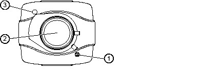
Front View
Figure 1-1 and the table that follows describe the front view of the IP camera.
Figure 1-1 Front View of IP Camera
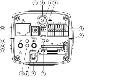
Back View
Figure 1-2 and the table that follows describe the back view of the IP camera.
Figure 1-2 Back View of IP Camera
|
|
Connection to an optional PoE power injector if your router or switch does not support PoE |
|
|
|
Connects to an optional video monitor that has a BNC connector |
|
|
|
Switches the microphone operation between to following options: |
|
|
|
||
|
|
GPIO terminal block that is used to connect external input and output devices. For more information, see Figure 1-3. |
|
|
|
The IP camera is compliant with Micro SD/SDHC (up to 32GB) and other preceding standard SD cards. |
|
|
|
Used in conjunction with an analog display to fine tune the IP camera focus. |
|
|
|
Connection for the cable from a P-iris lens. For more information, see Figure 1-4. |
|
|
|
||
|
|
||
|
|
Recessed button that reboots the IP camera or resets it to a default state. You can use a pin or paper clip to depress it. Depending on how long you depress the recessed reset button, you can do either of the following:
|
|
|
|
||
|
|
||
|
|
Accepts a standard LAN cable to connect the IP camera to a 10/100BaseT router or switch. |
General Purpose I/O Terminal Block
Figure 1-3 shows the pin locations and descriptions.
Figure 1-3 GPIO Terminal Block Pin Locations and Descriptions
|
|
|
|

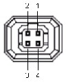
P-iris Lens Connector Pinouts
Figure 1-4 describes the pinouts of the P-iris lens connector on the IP camera.
Figure 1-4 P-iris Lens Connector Pinouts
|
|
|
|---|---|
P-iris Lens
Figure 1-5 and the table that follows describe the P-iris lens for the IP camera.

|
|
||
|
|
 Feedback